Installation, Operation, Maintenance
4
Installation, Operation & Maintenance - HBH/HBV Compact Series
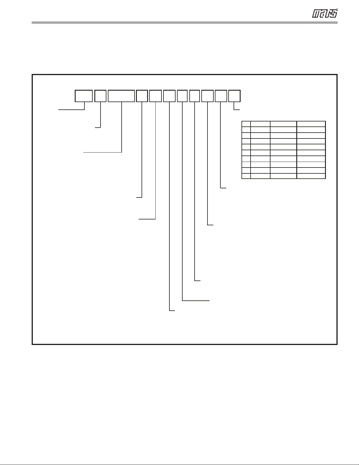
General Information
Safety
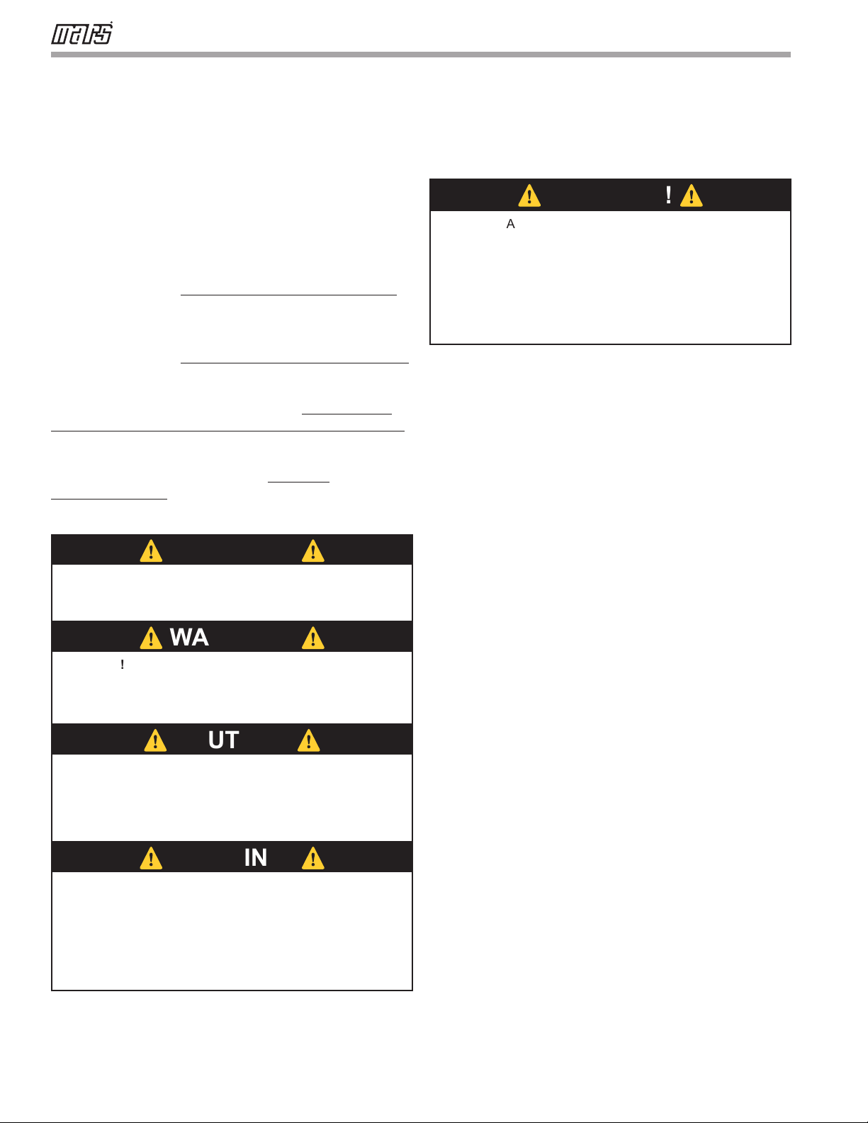
Warnings, cautions, and notices appear throughout this
manual. Read these items carefully before attempting any
installation, service, or troubleshooting of the equipment.
DANGER: Indicates an immediate hazardous situation,
which if not avoided will result in death or serious injury.
DANGER labels on unit access panels must be observed.
WARNING: Indicates a potentially hazardous situation,
which if not avoided could result in death or serious injury.
CAUTION: Indicates a potentially hazardous situation or
an unsafe practice, which if not avoided could result in
minor or moderate injury or product or property damage.
NOTICE: Notication of installation, operation, or
maintenance information, which is important, but which is
not hazard-related.
Inspection - Upon receipt of the equipment, carefully
check the shipment against the bill of lading. Make sure
all units have been received. Inspect the packaging of
each unit, and inspect each unit for damage. Ensure that
the carrier makes proper notation of any shortages or
damage on all copies of the freight bill and completes a
common carrier inspection report. Concealed damage
not discovered during unloading must be reported to the
carrier within 15 days of receipt of shipment. If not led
within 15 days, the freight company can deny the claim
without recourse.
Note: It is the responsibility of the purchaser to le
all necessary claims with the carrier. Notify your
equipment supplier of all damage within fteen (15)
days of shipment.
Storage - Equipment should be stored in its original
packaging in a clean, dry area. Store units in an upright
position at all times. Stack units a maximum of 3 units high.
Unit Protection - Cover units on the job site with
either the original packaging or an equivalent protective
covering. Cap the open ends of pipes stored on the
job site. In areas where painting, plastering, and/or
spraying has not been completed, all due precautions
must be taken to avoid physical damage to the units and
contamination by foreign material. Physical damage and
contamination may prevent proper start-up and may
result in costly equipment clean-up.
⚠
WARNING!
⚠
⚠
WARNING!
⚠
⚠
CAUTION!
⚠
⚠
WARNING!
⚠
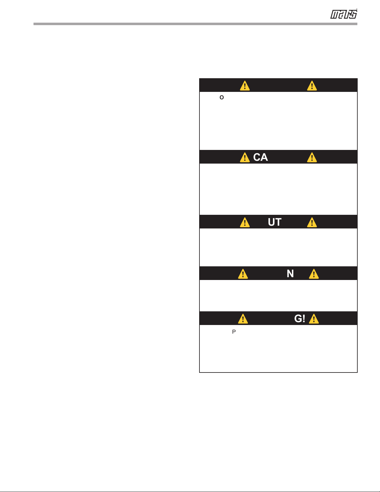
WARNING! To avoid the release of refrigerant into the
atmosphere, the refrigerant circuit of this unit must be
serviced only by technicians who meet local, state, and
federal prociency requirements.
CAUTION! To avoid equipment damage, DO NOT use
these units as a source of heating or cooling during the
construction process. The mechanical components and lters
can quickly become clogged with construction dirt and debris,
which may cause system damage and void product warranty.
WARNING! The Application and Service Manual should be
read and understood before attempting to service refrigerant
circuits with HFC-410A.
WARNING! The installation of water-source heat pumps and
all associated components, parts, and accessories which
make up the installation shall be in accordance with the
regulations of ALL authorities having jurisdiction and MUST
conform to all applicable codes. It is the responsibility of
the installing contractor to determine and comply with ALL
applicable codes and regulations.
⚠
WARNING!
⚠
WARNING! All refrigerant discharged from this unit must
be recovered WITHOUT EXCEPTION. Technicians must
follow industry accepted guidelines and all local, state, and
federal statutes for the recovery and disposal of refrigerants.
If a compressor is removed from this unit, refrigerant circuit
oil will remain in the compressor. To avoid leakage of
compressor oil, refrigerant lines of the compressor must be
sealed after it is removed.