Mars Comfort-Aire Century 7602-444 User manual

www.marsdelivers.com
Installation and
Operation Manual
7602-444
Communicating Service Tool
Table of Contents
Connection ..............................................................................3
Menu Structure........................................................................4
System Conguration ..............................................................4
Airow Selection......................................................................4
Option Selection ......................................................................5
Unit Conguration....................................................................5
Pump Conguration.................................................................6
Valve Conguration .................................................................6
Multi-Unit Conguration...........................................................7
Service Mode...........................................................................8
Manual Operation....................................................................8
Control Diagnosis ....................................................................8
Dipswitch Conguration...........................................................9
Fault History ............................................................................9
Clear Fault History................................................................. 11
Revision History.....................................................................12

Equivalent Model Numbers
Heat Controller Climate Master
HE-Series TZ
HZ-Series TE
HZS-Series TES
HB-Series 0.5-5T TC
HB-Series 7-25T TL
HKV-Series TL
HRC-Series TRC

3
IOM - 7602-444 Communicating Service Tool
Comfort-Aire/Century Communicating Service Tool 7602-444 allows install and service technicians to congure and diagnose
Comfort-Aire/Century Digital Communicating Units without installing a digital communicating thermostat.
Using the Service Tool, a technician can ELECTRONICALLY:
1. Congure items like: airow, heat pump options and conguration, pump or modulating valve operation, unit family, unit
size, etc.
AND
2. Diagnose the unit by operating it manually, performing control diagnostics, viewing dip switch congurations, or by
viewing fault history and operating conditions when a fault occurred.
The Service Tool connects to the DXM2 board with a 4-Wire Connector as shown below:
P1
Alarm
Relay
Comp
Relay
O
Y1
Y2
W
G
C
R
AL1
24Vdc
EH1
EH2
P6
R
C
Off On
JW3
A
OVR
ESD
C
R
NSB
AL2
JW1
Acc1
Relay
Acc2
Relay
H
COM
NC1
NO1
COM
NC2
NO2
P3 CO
RV
RV
LT1
LT1
LT2
LT2
LP
LP
HP
HP
P7
Status
Fault
R
R
CC
CCG
CO
S1
S2
1
12
1
4
Factory Use
(240Vac)
Com
N.O.
Fan Enable
5 1/2"
7" 6 1/2"
5"
Use 4 mounting screws
#6 sheet metal screw 1” long
1.5
3/8” standoff
Factory low
voltage Molex
connection for
unit harness
Factory low
voltage Molex
connection for
electric heat
harness
Micro
U1
Off On
P2
COH
COM
AO2
P11
Gnd T1
P10
T2 T2 T3 T3 T4 T4 T5
P9
T5
T6 T6
A0-1 A0-2
Off On
S3
RV
Relay
CCH
Relay
Test
P5
B-
Gnd
P4
A+ 24V
(240Vac)
Fan Speed
N.O.
N.C.
12V
OUT
Gnd
P8
IN
NC
P12
Note: There is only
one T1 connection
1 2 3 4
1 2 3 4 5 6 7 8
1 2 3 4 5 6 7 8
AO1
Gnd
1
Service tool
connection
DXM2
Board
DXM2DXM2
BoardBoard
1.0 Connection
� WARNING! �
WARNING!
Connecting wire harness while unit is powered on
or connecting backward may damage service tool.

4
IOM - 7602-4 Communicating Service Tool
2.0 Menu Structure
System Conguration
Airow Selection
Option Selection
Unit Conguration
Pump Conguration
Valve Conguration
Service Mode
Manual Operation
Control Diagnostics
Dipswitch Conguration
Fault History
Clear Fault History
Menu Structure
Start-up Screen
System Conguration Menu
SERVICE TOOL MENU
SYSTEM CONFIG
SERVICE MODE
ACDU03 1.00
SELECT OPTION
3.0 System Conguration
Use the System Conguration option on the start-up screen
to adjust critical equipment settings.
The System Conguration information will be automatically
obtained from each communicating control in the system.
Note 1: The Airow Selection menu (section 3.1) will not be
present if the connected communicating control system has
no blower.
Note 2: The Pump Conguration menu (section 3.4) will
not be present if the connected communicating control is
congured for No Loop Conguration (OTHER).
Note 3: The Valve Conguration menu (section 3.5) will
not be present if the connected communicating control is
congured for No Loop Conguration (OTHER).
3.1 AIRFLOW SELECTION
Adjust the airow settings for each system operating mode
using the up/down arrow buttons. Press the center button to
select each item.
• Airow Settings (defaults stored in control) -
valid range: obtained from control (in 25 CFM
increments)
• Blower O Delay (default 60 seconds) – valid
range: 0 to 255 seconds (in 5 second increments)
NOTE 1: The Airow Settings will only be present if the
connected communicating control is congured for ECM
blower.
NOTE 2: If multiple units are connected to one thermostat,
refer to section 3.6 for unit selection.
SYSTEM CONFIGURATION
AIRFLOW SELECTION
OPTION SELECTION
UNIT CONFIG TES026
PUMP CONFIGURATION
SELECT OPTION
PREVIOUS SELECT
or 7602-444

5
IOM - 7602-444 Communicating Service Tool
Option Selection Menu
Unit Conguration Menu
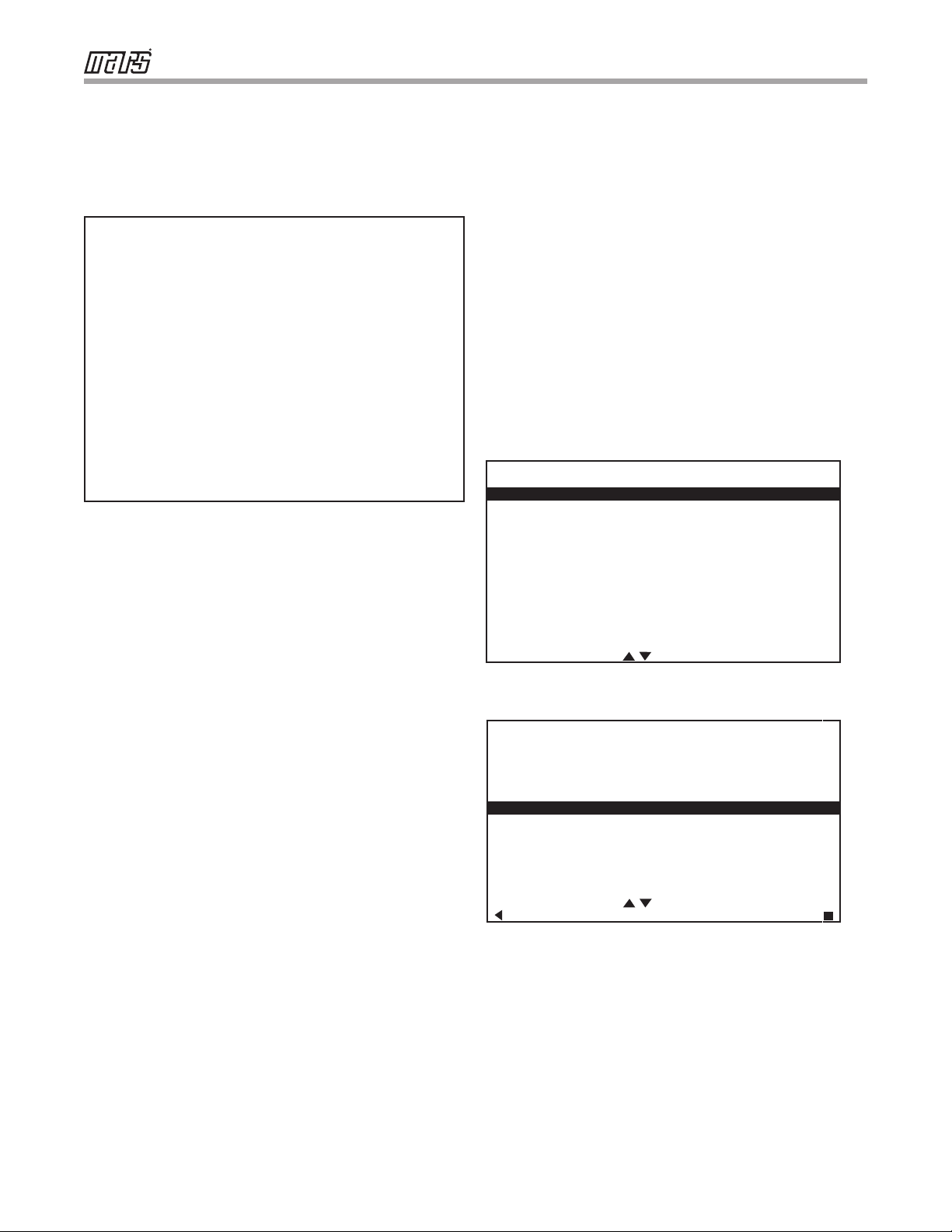
OPTION SELECTION
MOTORIZED VALVE OFF
COMPRESSOR ASCD 0
SELECT OPTION
PREVIOUS SELECT
NOTE: “Motorized Valve” used here refers to a two-position
motorized water valve, not to be confused with the modulating
motorized water valve found in the LOOP CONFIG.
3.2 OPTION SELECTION
This option allows the conguration of heat pump options to
be modied.
Adjust the Option settings using the up/down arrow buttons.
Press the center button to select each item.
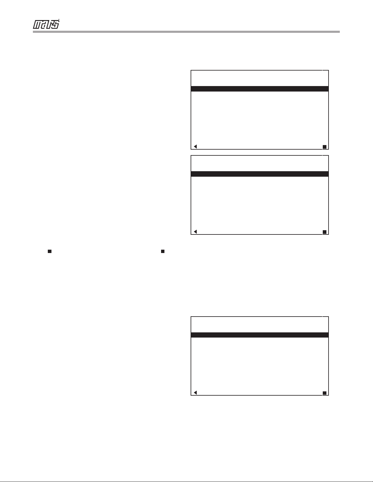
• Motorized Valve (defaults stored in control) – valid
range: O, On “On” delays compressor start until
the valve is fully open.
• Compressor ASCD (Anti-Short Cycle Delay (default
stored in control) – valid range: 5 to 8 (in 1 minute
increments)
NOTE 1: The Compressor Anti-Short Cycle Delay setting
provides equipment protection by forcing the compressor to
wait a few minutes before restarting.
NOTE 2: If multiple units are connected to one thermostat,
refer to section 3.6 for unit selection.
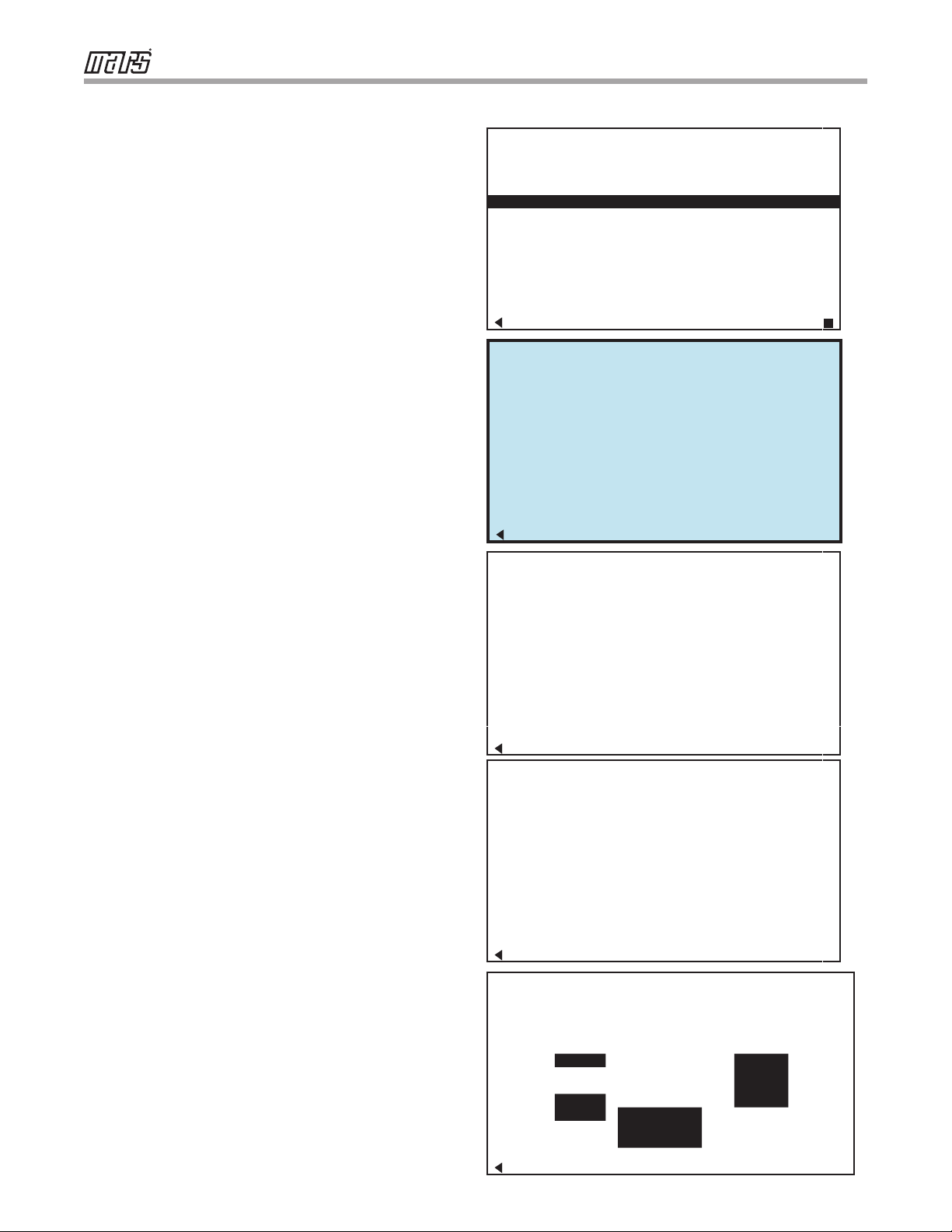
3.3 UNIT CONFIGURATION
Adjust the Unit Conguration settings including Heat
Pump Family, Heat Pump Size, Blower Type, and Loop
Conguration using the up/down arrow buttons. Press the
center button to select each item.
• Heat Pump Family (default stored in control) –
valid range: TE, TY, TES, TEP, TRT, TSM, TSL
• Heat Pump Size (default stored in control) – valid
range: depends on Heat Pump Family setting
• Blower Type (default stored in control) – valid
range: NO BLOWER, 2-SPD PSC, COM ECM-V,
1-SPD PSC, 2-SPD CTM, PWM ECM, VFD
• Loop Cong (default stored in control) – valid
range: Other, VS PUMP, MOD VALVE
Airow, pump and valves can be congured from ‘System
Conguration’ screen.
Select ‘VS PUMP PARALLEL’ when applying an internal
variable speed ow controller with other ow controllers on a
single loop in parallel.
NOTE: Refer to section 3.6.3 for multi-unit conguration
instructions.
UNIT CONFIGURATION
CURRENT CONFIG TE026
HEAT PUMP FAMILY TE
HEAT PUMP SIZE 026
BLOWER TYPE ECM
LOOP CONFIG VS PUMP
SELECT OPTION
PREVIOUS SAVE
Equivalent Model Numbers
Heat Controller Climate Master
HE-Series TZ
HZ-Series TE
HZS-Series TES
HB-Series 0.5-5T TC
HB-Series 7-25T TL
HKV-Series TL
HRC-Series TRC

6
IOM - 7602-4 Communicating Service Tool
VARIABLE SPD INTERNAL
PUMP CONFIGURATION
LOOP OPTION SINGLE
PUMP CONTROL FIXED
HEATING STAGE 1 60%
COOLING STAGE 2 75%
COOLING STAGE 1 50%
COOLING STAGE 2 70%
PREVIOUS SELECT
3.4 PUMP CONFIGURATION
vFlow™ vs internal ow control pump can be controlled either
through temperature dierential (Delta T) or can be set to
specic speed (xed; % of full speed for each heat and cool
stage).
Can be congured for either single pumping or parallel
pumping.
Congure temperature dierentials at the thermostat for
vFlow™ units with an internal ow control pump.
Adjust the Pump Conguration settings using the up/down
arrow buttons. Press the center button to select each item.
• Heating Delta T (default stored in control) –
valid range: 4 to 12ºF (in 1ºF increments)
• Cooling Delta T (default stored in control) –
valid range: 9 to 20ºF (in 1ºF increments)
Maximum Heat LWT (valid range based on specic model;
refer to model IOM). Minimum Cool LWT (valid range based
on specic model; refer to model IOM).
NOTE: Refer to section 3.6.3 for multi-unit conguration
instructions.
To control vs pump by xed speed, select ‘Pump Control’,
press , use down arrow to select ‘Fixed’, and press to
save.
Default stored in control. Valid range: 15% - 90% (in 1%
increments)
Heating Stage 1 Cooling Stage 1
Heating Stage 2 Cooling Stage 2
If Pump Conguration is set to ‘VS PUMP PARALLEL’, valid
range changes to 50-90% (in 1% increments).
3.5 VALVE CONFIGURATION
Congure temperature dierentials at the thermostat for
vFlow™ units with a motorized modulating valve.
Adjust the Valve Conguration settings using the up/down
arrow buttons. Press the center button to select each item.
• Heating Delta T (default stored in control) –
valid range: 4 to 12ºF (in 1ºF increments)
• Cooling Delta T (default stored in control) –
valid range: 9 to 20ºF (in 1ºF increments)
NOTE 1: Minimum and Maximum degree values are shown
only when the control is congured with the appropriate
values.
NOTE 2: Refer to section 3.6.3 for multi-unit conguration
instructions.
3.5.1 MODULATING VALVE OFF POSITION
For certain commercial multi-unit applications, the modulating
valve can be kept slightly open by choosing values 3.3-4.0.
MODULATING VALVE
CONFIGURATION
OFF POSITION 0.0
VALVE CONTROL DELTA T
HEATING DELTA T 7 F
COOLING DELTA T 10 F
MAXIMUM HEAT LWT 80 F
MINIMUM COOL LWT 40 F
PREVIOUS SELECT
VARIABLE SPD INTERNAL
PUMP CONFIGURATION
LOOP OPTION PARALLEL
PUMP CONTROL DELTA T
HEATING DELTA T 7 F
COOLING DELTA T 10 F
MAXIMUM HEAT LWT 80 F
MINIMUM COOL LWT 40 F
PREVIOUS SELECT

7
IOM - 7602-444 Communicating Service Tool
Two
connections
on DXM2
board to allow
for multi-unit
installation
Or
AIRFLOW SELECTION
TT026 S N - - - - - 1 2 3 4
TT026 S N - - - - - 5 6 7 8
TT038 S N - - - - - 9 0 1 2
PREVIOUS SELECT
OPTION SELECTION
TT026 S N - - - - - 1 2 3 4
TT026 S N - - - - - 5 6 7 8
TT038 S N - - - - - 9 0 1 2
PREVIOUS SELECT
3.6 MULTI-UNIT CONFIGURATION
If multiple units are connected to one 7602-457 thermostat
upon unit start-up, the thermostat will automatically register
the serial numbers of all units connected to it.
NOTE: Multiple units may be connected directly to the 7602-
457 thermostat or connected to one another in series, as
shown by the gure below.
3.6.1 MULTI-UNIT AIRFLOW SELECTION
In section 3.1, when an installer selects “Airow Selection”
from the System Conguration menu, the installer may
choose the unit to congure by the last 4 digits of its serial
number from the following screen.
3.6.2 MULTI-UNIT OPTION SELECTION
In section 3.2, when an installer selects “Option Selection”
from the System Conguration menu, the installer may
choose the unit to congure by the last 4 digits of its serial
number from the following screen.
3.6.3 Multi-Unit, Unit, Pump, & Valve Conguration
To congure Unit, Pump, and Valve options in sections 3.3-
3.5, the thermostat must be connected to only one unit at a
time.

8
IOM - 7602-4 Communicating Service Tool
4.0 Service Mode
4.1 MANUAL OPERATION
Manual Operation mode allows service personnel to manually
command operation for any of the thermostat outputs, blower
speed, as well as pump speed or valve position to help
troubleshoot specic components.
NOTE 1: The ECM Airow adjustment will not be present if the
connected communicating control (DXM2) is not congured for
ECM (section 3.1).
NOTE 2: The Pump Speed adjustment will not be present
if the connected communicating control (DXM2) is not
congured for Pump (section 3.4).
NOTE 3: The Valve Position adjustment will not be present if
the connected communicating control (DXM2) is congured for
Valve (section 3.5).
4.2 CONTROL DIAGNOSTICS
Control Diagnostics mode allows service personnel to view
the status of all physical inputs, switches and temperature
sensor readings, as well as the operational status of the heat
pump at the thermostat.
Navigate between diagnostic screens using the left/right
arrow buttons.
NOTE: The Pump Status will not be present if the connected
communicating control (DXM2) is not congured for Pump
(section 3.4).
SERVICE MODE
MANUAL OPERATION
CONTROL DIAGNOSTICS
DIPSWITCH CONFIG
FAULT HISTORY
CLEAR FAULT HISTORY
SELECT OPTION
PREVIOUS SELECT
MANUAL OPERATING MODE
Y1 COMM OUTPUT OFF
Y2 COMM OUTPUT OFF
WCOMM OUTPUT OFF
O COMM OUTPUT OFF
GCOMM OUTPUT OFF
HCOMM OUTPUT OFF
DH COMM OUTPUT OFF
ECM AIRFLOW 0
PUMP SPEED 0%
TEST MODE OFF
SELECT OPTION
PREVIOUS SELECT
CONTROL STATUS
TEMPERATURES
LT1 TEMP 38.1
LT2 TEMP 79.9
COMP DISCHARGE 157.7
HOT WATER EWT 121.5
LEAVING AIR 75.1
LEAVING WATER 73.3
ENTERING WATER 78.5
CONTROL VOLTAGE 26.4
ECM BLOWER RPM 550
ECM TARGET CFM 800
ECM BLWR STATIC N/A
PREVIOUS NEXT
CONTROL DIAGNOSTICS
HP SWITCH CL
LOC SWITCH CL
Y1 PHYSICAL INPUT ON
Y2 PHYSICAL INPUT OFF
W PHYSICAL INPUT OFF
O PHYSICAL INPUT ON
G PHYSICAL INPUT ON
H PHYSICAL INPUT OFF
EMERG SHUTDOWN OFF
NIGHT SETBACK OFF
OVR INPUT OFF
PREVIOUS NEXT
CONTROL DIAGNOSTICS
PUMP OPERATION
PUMP SPEED 60%
PUMP WATTS 140
FLOW RATE GPM 7.4
PREVIOUS

9
IOM - 7602-444 Communicating Service Tool
4.3 DIPSWITCH CONFIGURATION
Dipswitch Conguration mode allows the service personnel
to view the status of all dipswitch settings for the connected
communicating control (DXM2/AXM) at the thermostat.
Navigate between conguration screens using the left/right
arrow buttons.
NOTE: The unit control dipswitch settings cannot be changed
from the thermostat or conguration/diagnostics tool.
S1 Dipswitch Status
S2 Dipswitch Status
S3 Dipswitch Status
Fault History
CONTROL CONFIGURATION
DIPSWITCH S1
1 ON UPS ENABLED
2 ON DUAL COMP STG 1
3 ON HEAT PUMP TSTAT
4 ON RV O THERMOSTAT
5 ON DEHUMID OFF
6 ON EH2 AUX HEAT
7 ON BOILERLESS
8 ON SEE DXM2 AOM
PREVIOUS NEXT
CONTROL CONFIGURATION
DIPSWITCH S2
1 ON \ ACCESSORY 1
2 ON ACCESSORY 2
3 ON/
4 ON \ ACCESSORY 2
5 ON ACTIVE W/ COMP
6 ON /
7 ON H DEHUM INPUT
8 ON FACTORY SETTING
PREVIOUS NEXT
CONTROL CONFIGURATION
DIPSWITCH S3
1 ON FACTORY SETTING
2 OFF HWG TEST OFF
3 OFF HWG SP 125
4 OFF HWG DISABLED
JW3 LT1 SETTING WELL
PREVIOUS
TT038 SN - - - - - 0 1 2 3
LAST 5 FAULTS
LT1 LOW WATER TEMP
NO FAULT
NO FAULT
NO FAULT
NO FAULT
NEXT
PREVIOUS SELECT
4.4 FAULT HISTORY
Fault History mode displays the ve most recent stored fault
codes for the connected communicating control (DXM2).
Navigate between control fault codes using the up/down
arrow buttons. Press the center button to view more
information about the highlighted fault code.

10
IOM - 7602-4 Communicating Service Tool
4.4.1 Temperature Conditions
Displays detailed temperature readings that were
recorded at the time the fault occurred
4.4.0 Fault Conditions Menu
4.4.2 Flow Conditions
Displays detailed blower and pump speed / valve posi-
tion readings that were recorded at the time the fault
occurred.
4.4.3 Input/Output Conditions
Displays the status of all physical and communicated
inputs, switches, and control outputs that were re-
corded at the time the fault occurred.
FAULT CONDITION MENU
LT1 LOW WATER TEMP
HEAT 1 11:11 AM 11/14
FAULT TEMP CONDITIONS
FAULT FLOW CONDITIONS
FAULT I/O CONDITIONS
FAULT CONFIG COND
FAULT POSSIBLE CAUSES
PREVIOUS SELECT
FAULT TEMPERATURE CONDITIONS
LT1 LOW WATER TEMP
HEAT 1 11:11 AM 11/14
LT1 TEMP 28.1
LT2 TEMP 97.3
HOT WATER EWT 121.5
COMP DISCHARGE 157.7
LEAVING AIR 92.7
LEAVING WATER 34.9
ENTERING WATER 42.1
CONTROL VOLTAGE 26.4
PREVIOUS
FAULT I / O CONDITIONS
LT1 LOW WATER TEMP
HEAT 1 11:11 AM 11/14
TSTAT SAFETY OUTPT
CONV COMM HPS
Y1 Y1 LOC CC
Y2 Y2 CO RV
W W ACC1
OOOUTPT ACC2
GGFAN AL1
H H HWG EH1
OVR DH PUMP EH2
PREVIOUS
FAULT FLOW CONDITIONS
LT1 LOW WATER TEMP
HEAT 1 11:11 AM 11/14
ECM TARGET CFM 800
ECM BLOWER RPM 550
FLOW RATE GPM 6.5
PUMP SPEED 60%
PUMP WATTS 140
LOOP CONFIG VS PUMP
PREVIOUS SINGLE
FAULT FLOW CONDITIONS
LT1 LOW WATER TEMP
HEAT 1 11:11 AM 11/14
ECM TARGET CFM 800
ECM BLOWER RPM 550
VALVE POSITION 10.0V
LOOP CONFIG MOD VALVE
PREVIOUS MIN POS

11
IOM - 7602-444 Communicating Service Tool
4.4.3 Conguration Conditions
Displays the status of all dipswitch settings that were
recorded at the time the fault occurred.
4.4.4 Possible Causes
Displays possible causes as to why the fault occurred
4.5 CLEAR FAULT HISTORY
Clear Fault History will clear all fault codes stored in the
thermostat as well as the fault history in any connected
communicating controls (DXM2/AXM).
FAULT CONFG CONDITIONS
LT1 LOW WATER TEMP
HEAT 1 11:11 AM 11/14
S1 S2 S3
1 ON 1 ON 1 ON
2 ON 2 ON 2 OFF
3 ON 3 ON 3 OFF
4 ON 4 ON 4 OFF
5 ON 5 ON
6 ON 6 ON LT1 WELL
7 ON 7 ON LT2 WELL
8 ON 8 ON
PREVIOUS
POSSIBLE FAULT CAUSES
LOW WATER COIL TEMP
LOW WATER TEMP - HTG
LOW WATER FLOW - HTG
LOW REFRIG CHARGE - HTG
INCORRECT LT1 SETTING
BAD LT1 THERMISTOR
PREVIOUS

12
IOM - 7602-4 Communicating Service Tool
:HOOZRUWK$YH-DFNVRQ0,3KZZZKHDWFRQWUROOHUFRP
'XHWRRQJRLQJSURGXFWLPSURYHPHQWVVSHFLILFDWLRQVDQGGLPHQVLRQVDUH
VXEMHFWWRFKDQJHDQGFRUUHFWLRQZLWKRXWQRWLFHRULQFXUULQJREOLJDWLRQV'HWHUPLQLQJWKH
DSSOLFDWLRQDQGVXLWDELOLW\IRUXVHRIDQ\SURGXFWLVWKHUHVSRQVLELOLW\RIWKHLQVWDOOHU
$GGLWLRQDOO\WKHLQVWDOOHULVUHVSRQVLEOHIRUYHULI\LQJGLPHQVLRQDOGDWDRQWKHDFWXDOSURGXFW
SULRUWREHJLQQLQJDQ\LQVWDOODWLRQSUHSDUDWLRQV
,QFHQWLYHDQGUHEDWHSURJUDPVKDYHSUHFLVHUHTXLUHPHQWVDVWRSURGXFWSHUIRUPDQFH
DQGFHUWLILFDWLRQ$OOSURGXFWVPHHWDSSOLFDEOHUHJXODWLRQVLQHIIHFWRQGDWHRIPDQXIDFWXUH
KRZHYHUFHUWLILFDWLRQVDUHQRWQHFHVVDULO\JUDQWHGIRUWKHOLIHRIDSURGXFW
7KHUHIRUHLWLVWKHUHVSRQVLELOLW\RIWKHDSSOLFDQWWRGHWHUPLQHZKHWKHUDVSHFLILF
PRGHOTXDOLILHVIRUWKHVHLQFHQWLYHUHEDWHSURJUDPV
6/2022
ZZZPDUVGHOLYHUVFRP
1900 Wellworth Ave., Jackson, MI 49203 • Ph. 517-787-2100 • www.marsdelivers.com
Table of contents