Marshall Amplification CV6XX-HFH User manual

Broadcast A/V Division
CV6XX-HFH
Compact Weatherproof Dome Housing
for PTZ Cameras
User Manual

1. Product Instructions
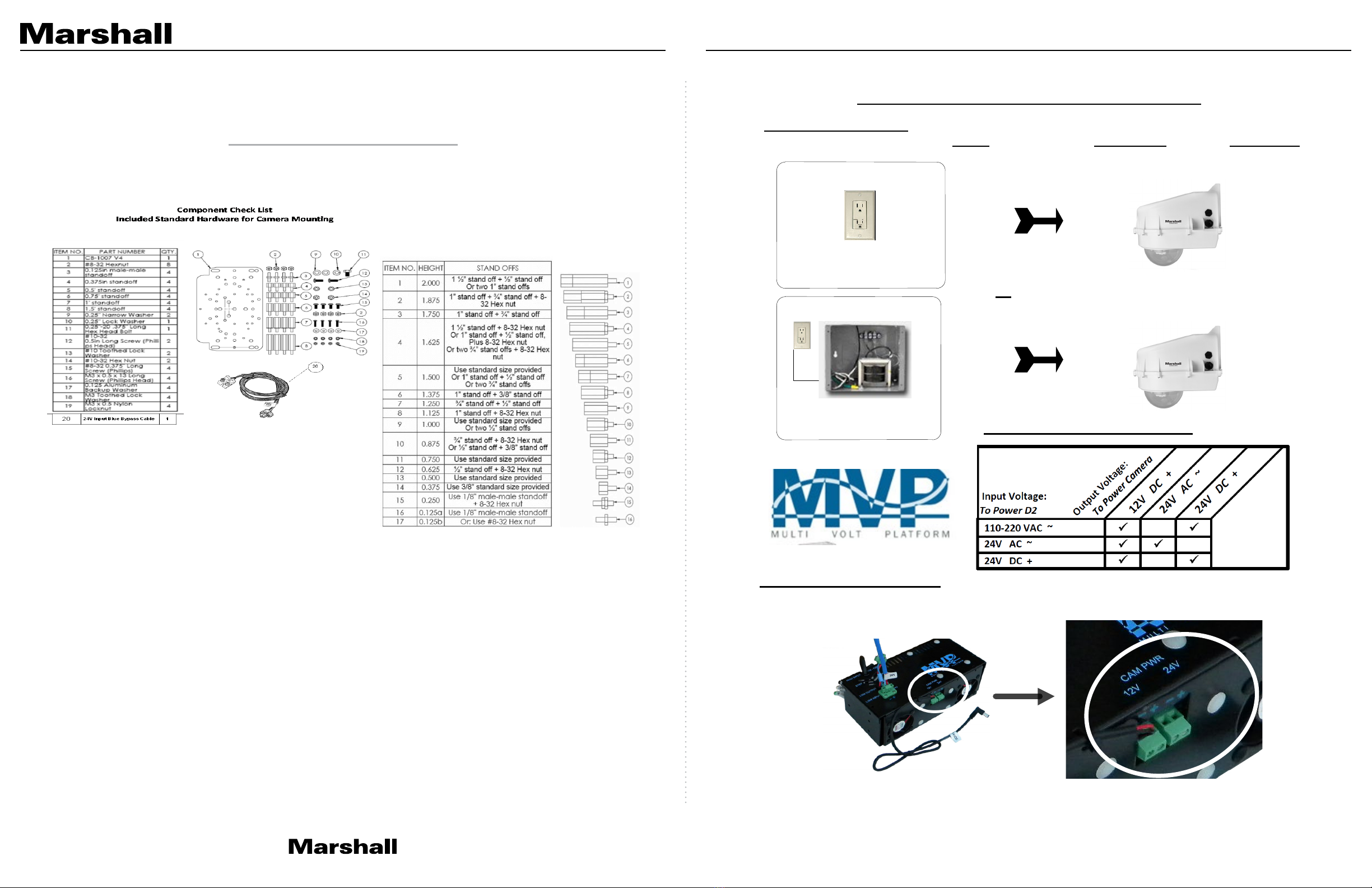
2. MVP Voltage Matrix
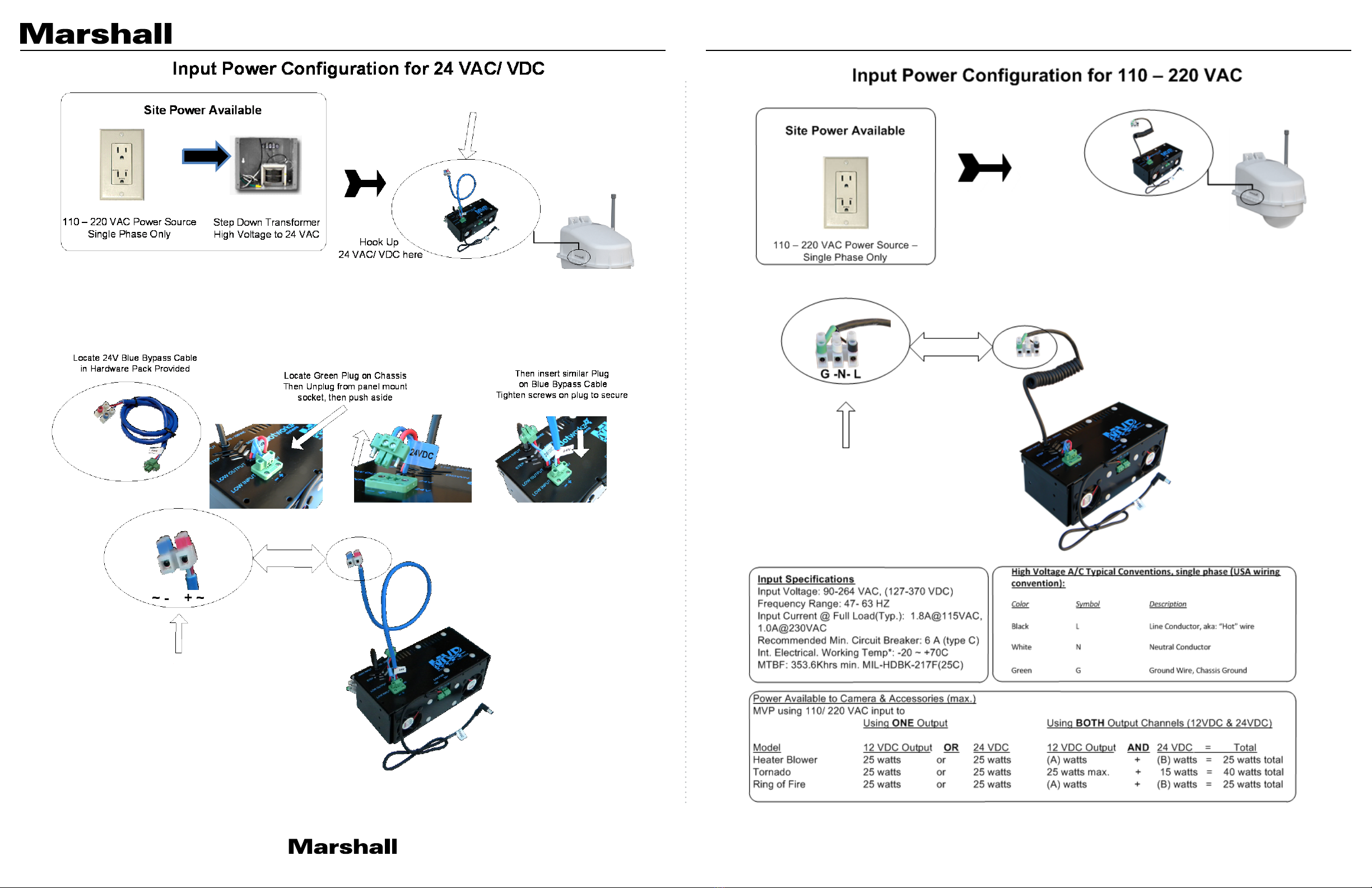
4. Input Power Configuration for 110 -220 VAC
3. Input Power Configuration for 24 VAC/VDC
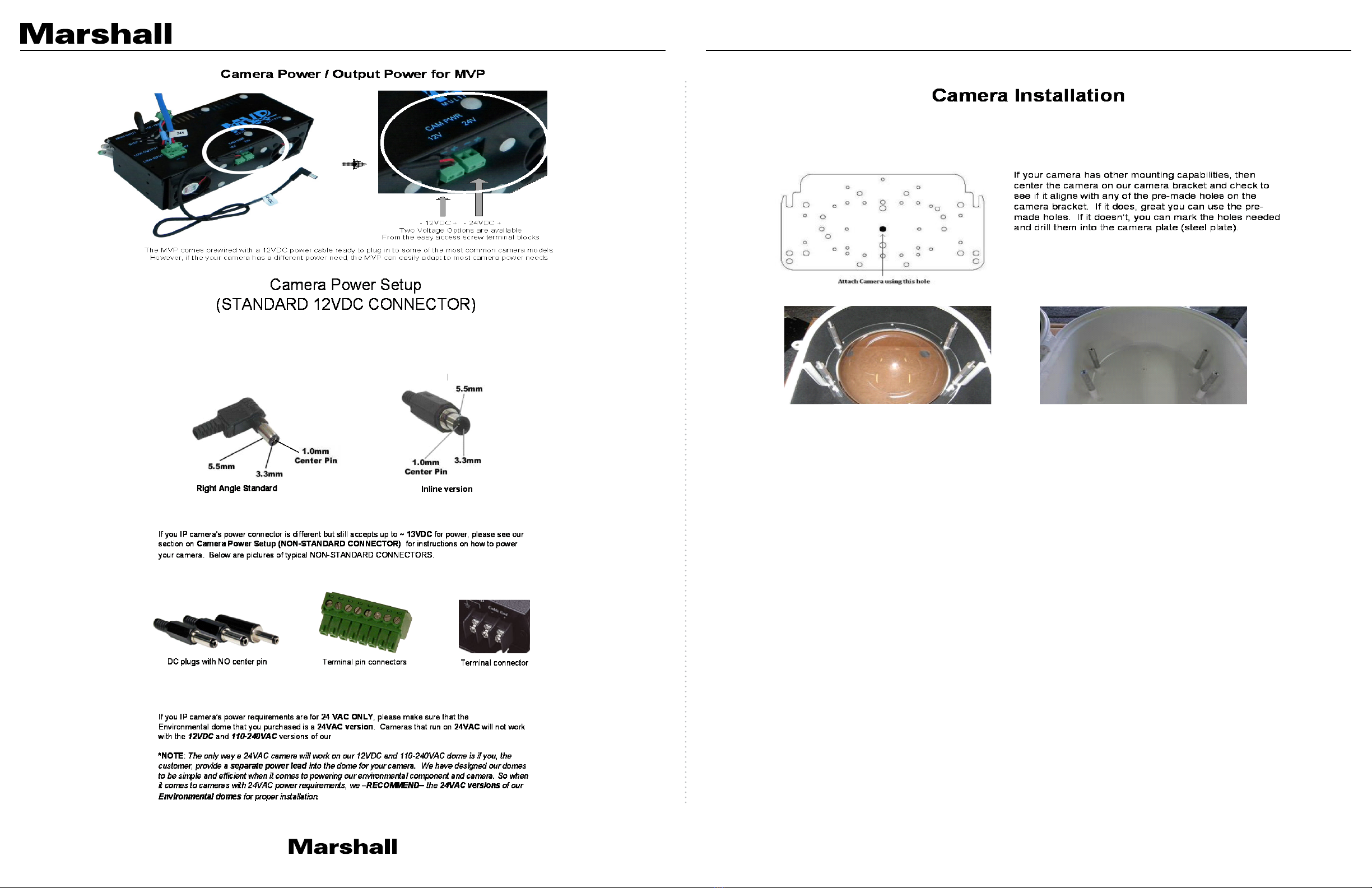
6. Camera Installation
5. Camera Power/ Output Power for MVP
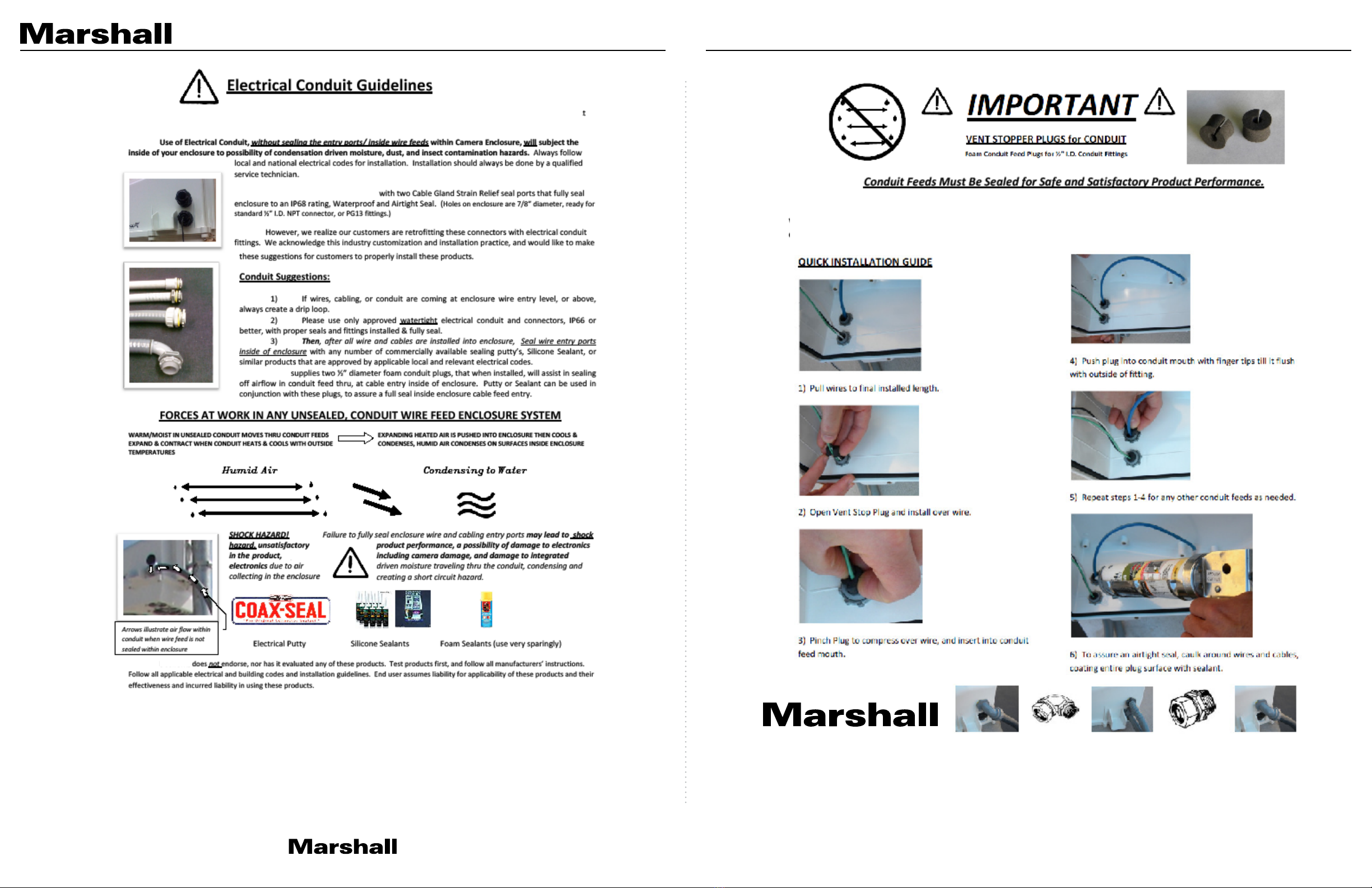
7. Electrical Conduit Guidelines
8. Vent Stopper Plugs
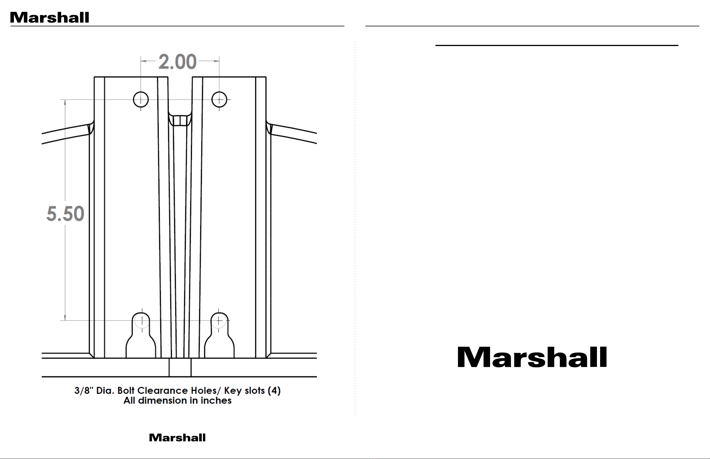
9. Dimensions
Warranty
02
04
05
06
07
08
11
12
13
14
0
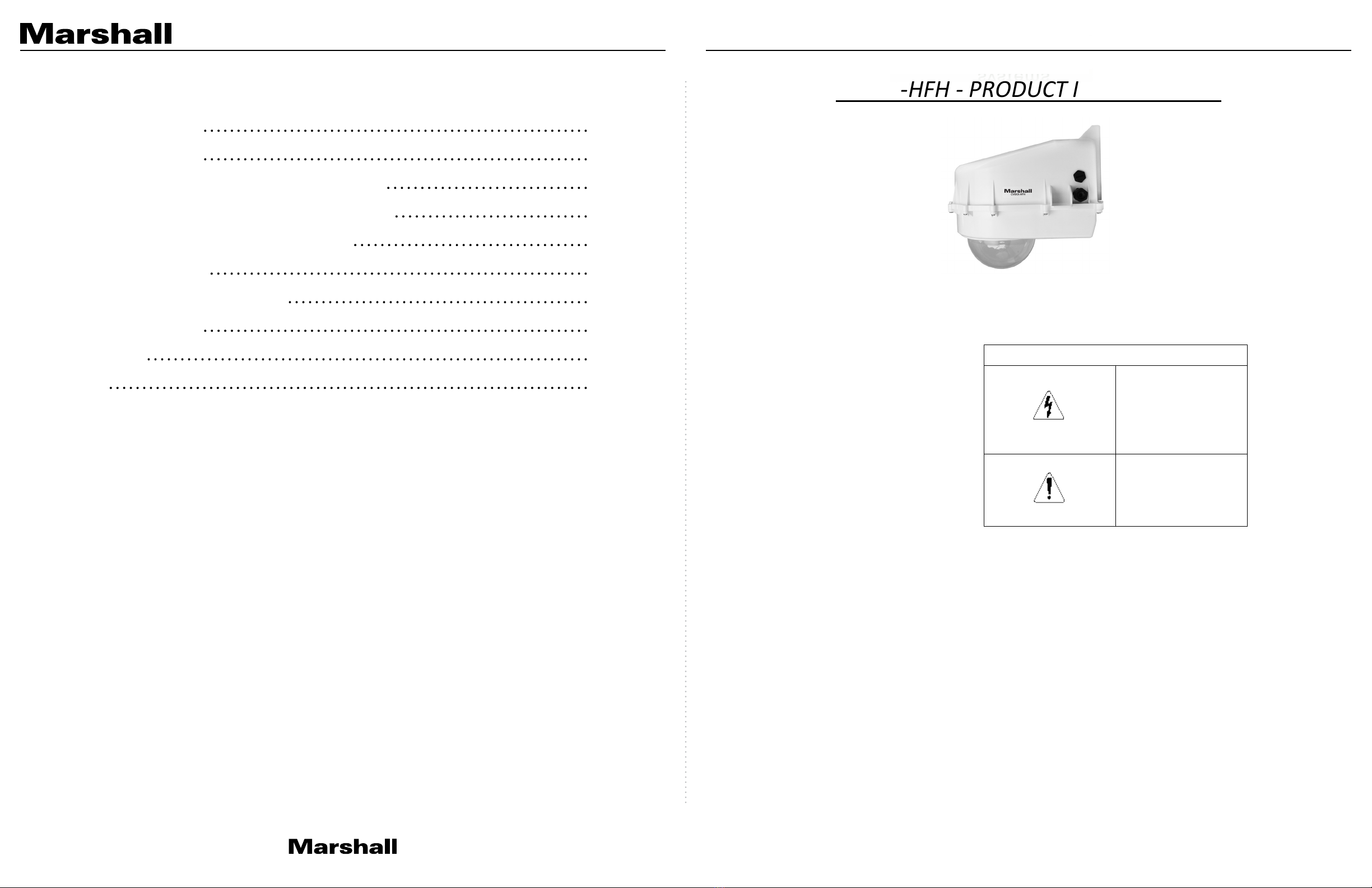
CV6XX-HFH - PRODUCT INSTRUCTIONS
PRODUCT INSTALLATION
PRECAUTIONS – WARNINGS – ADDITIONAL INFORMATION
IMPORTANT SAFEGUARDS
1Read Instructions - All the safety and operating instructions should be read
before the unit is operated.
2Retain Instructions -The safety and operating instructions should be retained for
future reference.
3. Heed Warnings - All warnings on the unit and in the operating instructions
should be adhered to.
4. Follow Instructions -All operating & user instructions should be followed.
5. Electrical Connections - Only a qualified electrician should make electrical
connections.
6. Attachments - Do not use attachments not recommended by the product
manufacturer as they may cause hazards
7. Cable Runs - All cable runs must be within permissible distance
8. Mounting -This unit must be properly and securely mounted to a supporting
structure capable of sustaining the weight of the unit. Accordingly:
a. Installation should be made by a qualified installer.
b. Installation should be in compliance with local codes
c. Care should be exercised to select suitable hardware to install the unit,
taking into account both the composition of the mounting surface and
the weight of the unit. Be sure to periodically examine the unit and the
supporting structure to make sure that the integrity of the
installation
is intact. Failure to comply with the foregoing could result in the unit
separating from the support structure and falling, with resultant damages
or injury to anyone or anything struck by the failing unit,
SERVICE
If the unit is defective and falls within the 1 year warranty, customer should contact
Marshall Electronics Inc. (800) 800-6608 for return authorization & shipping
instructions
CAUTION: TO REDUCE THE RISK OF ELECTRICAL SHOCK, DO NOT EXPOSE
COMPONENTS TO WATER OR MOISTURE
The lightning flash with an arrowhead
symbol, within an equilateral triangle,
is intended to alert the user to the
presence of non-insulated "dangerous
voltage" within the product's enclosure
that may be of sufficient magnitude to
constitute a risk of electric shock to
persons
The exclamation point within an
equilateral triangle is intended to
alert the user to the presence of
important operating and
maintenance (servicing) instructions
in the literature accompanying the
appliance
UNPACKING
Unpack carefully. Electronic components can be damaged if improperly handled
or dropped. If an item appears to have been damaged in shipment, replace it
properly in its carton and notify the shipper. Be sure to save
1.The shipping carton and packaging material. They are the safest material in
which to make future shipments of the equipment.
2. These Installation and Operating Instructions.
For technical questions or product returns – call
Marshall Electronics Inc. Customer Service (800-800-
6608)
The External Nut on All electrical wire feed Glands must be tightened to create a weather tight seal prior to putting CV6XX-HFH in
service. Failure to create this seal may result in water incursion into enclosure. This may lead to electrical shock, product failure and
damage to electrical systems installed within enclosure, including but not limited to damage to camera, heater and blower circuitry,
cooling circuitry and other systems installed in unit.
All screws on hinged lower must be tightened to create seal on enclosure. Failure to create this seal may result in water incursion into
enclosure. This may lead to electrical shock, failure and damage to electrical systems installed within enclosure, including but not limited
to damage to camera, heater and blower circuitry, cooling circuitry and other systems installed in unit.
Do not over tighten any Screws, Stand Offs, or other fasteners on this unit. Failure to heed this warning will cause damage or failure of
the CV6XX-HFH enclosure.
CV6XX-HFH Manual
www.marshall-usa.com1 2

1
Be sure to take extra care to Protect Lens of unit prior to and during installation, and during service. Suspension packaging box is a handy
platform to protect lens and enclosure, while installing camera and accessory electronics before installation. Failure to protect lens will
adversely affect product perform
Hardware Pack Provided with CV6XX-HFH Housing
Camera mount stand offs can be adjusted to any height from 0” to 3.75” using assembly logic illustrated above right. By utilizing both the camera
mounts inside the CV6XX-HFH; the upper mounts, and the lower mounts around the lens on hinged lower of CV6XX-HFH, virtually any PTZ or Mini-
Dome Camera can be mounted into the enclosure at any level.
Stand Off Height Assembly Table
for Camera Height Adjustment
2
Site Power Available
110 – 220 VAC
Power Source – Single Phase Only
24 VAC/VDC
Step Down Transformer
High Voltage to 24 VAC
Site Power Available
MVP Voltage Matrix: Enclosure Input – Camera Output
Input Voltage to Enclosure
The MVP Enclosures can be powered by
Inputs
of either High Voltage
110-220 VAC
. Or Low Volt
24 VAC/ VDC
Or
Output Voltage to Power Camera
MVP provides step down voltage to supply camera power for 12VDC, and 24V Cameras. 24V Camera Supply
24V output depends on Site Power Input, for either 24V Direct Current, or Alternating Current (see table above)
Voltage Matrix for Input / Output
*Optional 24VAC Transformer Module available
for 24VAC only cameras to convert 110-220 VAC to 24 VAC (sold separately)
Power Chassis integrated
into D-Series MVP
CV6XX-HFH Manual
www.marshall-usa.com3 4

3
4
Inside all CV6XX-HFH is a Chassis
similar to shown
Cable and connecons are made
fully inside of CV6XX-HFH
Run 24V into CV6XX-HFH and
Connect wires to appropriate color
coded terminal shown here
Run 110-220 VAC into CV6XX-HFH and connect wires
to appropriate color coded terminal shown here
CV6XX-HFH
Use black coiled cable for high voltage input to hook
up power inside CV6XX-HFH
The MVP comes ready for 110-220VAC Input power
To use 24 VAC/VDC you must take a moment to allow input conguraon for Low Voltage Input USE Blue24
VAC Bypass Cable to hook up power inside CV6XX-HFH
3
4
CV6XX-HFH Manual
www.marshall-usa.com5 6

5
5
6
6
All CV6XX-HFH environmental enclosures come standard with a 12VDC Right Angle Barrel Plug (3.3mm x
5.5mm with a 1mm center pin) for a majority of the IP cameras on the market.
The CV6XX-HFH Enclosure series can accommodate mini-domes and PTZ cameras as tall as 9.375 inches in height. Our stando combinaon includes
supported heights of 0.50”, 0.74”, 1.00”, 1.25”, 1.50”, 1.75”, 2.00”, 2.25”, 2.50”, 2.75”, 3.00”, and 3.75”. These stando heights can be applied to
upper and lower mount locaons based on the height of your camera. Most cameras will oen ulize a center screw hole for securing the camera
onto the plate.
For power, all of our CV6XX-HFH Environmental Enclosure Series come
standard with a 12VDC Barrel plug with a center pin. if your camera does
not support this, then check our secon on Camera Power Setup (NON-
STANDARD CONNECTOR) for details.
Upper CV6XX-HFH Dome SeconLower Lens Secon
CV6XX-HFH
CV6XX-HFH Environmental domes.
CV6XX-HFH Manual
www.marshall-usa.com7 8

7
This edge nests in arch at front of CV6XX-HFH
In order to mount the CV612/CV620/CV630
CAMERA you must install the PTZ cameras
included Ceiling Mount (CV620-CM-KIT)
This will allow for hole alignment on the
CB-1007 V4 MOUNTING PLATE.
CV6XX-HFH
1. Install the PTZ camera onto the CV6XX-HFH Camera
Bracket with (3) m3-.5, (3) m3 external lock washers, and
(3) m3 1/8” washer that are included.
2. The PTZ camera requires a 2.25” spacing for opmal
t and operaon. Use (1) 1.5” standos and (1) .75”
stando that are provided to create a 2.25” stando.
You will need to create 4 of these with the included.
hardware.
This edge of the bracket faces back of the CV6XX-HFH enclosure
CV6XX-HFH
9
CV6XX-HFH
CV6XX-HFH
This edge of the bracket faces back of the CV6XX-HFH Enclosure
CV6XX-HFHPTZ
PTZ
CV6XX-HFH
9
9
CV6XX-HFH Manual
www.marshall-usa.com9 10

10
For opmal performance, your CV6XX-HFH Enclosure is designed to be air & water ght to eliminate any moisture, dust, and
insect damage that can cause performance, reliability and maintenance related issues.
Marshall has provided each CV6XX-HFH
Marshall
Marshall
10
11
CV6XX-HFH Exploded Detail
Conduit Stopper Plugs prevent Humid Air exchange from venng through external conduit into Marshall sealed enclosure, when conduit
is used with Marshall enclosures. Vent Stopper Plugs eliminate conduit driven condensaon in surveillance camera enclosures, or other
outdoor enclosure products.
CV6XX-HFH Manual
www.marshall-usa.com11 12

12
CV6XX-HFH Mounting Detail
20608 Madrona Avenue, Torrance, CA 90503
Tel: (800) 800-6608 / (310) 333-0606 • Fax: 310-333-0688
www.marshall-usa.com
Marshall Electronics warranties to the first consumer that this device will, under normal use,
be free from defects in workmanship and materials, when received in its original container, for
a period of two years from the purchase date. This warranty is extended to the first consumer
only, and proof of purchase is necessary to honor the warranty. If there is no proof of purchase
provided with a warranty claim, Marshall Electronics reserves the right not to honor the warranty
set forth above. Therefore, labor and parts may be charged to the consumer. This warranty
does not apply to the product exterior or cosmetics. Misuse, abnormal handling, alterations or
modifications in design or construction void this warranty. No sales personnel of the seller or
any other person is authorized to make any warranties other than those described above, or to
extend the duration of any warranties on behalf of Marshall Electronics, beyond the time period
described above.
Due to constant effort to improve products and product features, specifications may change
without notice.
Warranty
NB01062021
CV6XX-HFH Manual
www.marshall-usa.com13 14
Table of contents
Other Marshall Amplification Camera Accessories manuals