cont. on page 12
IMPORTANT SAFEGUARDS
1. Read Instructions – All the safety and operating instructions should be read before operating the unit.
2. Retain Instructions – The safety and operating instructions should be retained for future reference.
3. Heed Warnings – All warnings on the unit and in the operating instructions should be adhered to.
4. Follow Instructions – All operating user instructions should be followed.
5. Electrical Connections – Only a qualified electrician should make the electrical connections.
6. Attachments – Do not use attachments not recommended by the product manufacturer as they may cause
hazards.
7. Cable Runs – All cable runs must be within permissible distance.
8. Mounting – This unit must be properly and securely mounted to a supporting structure capable of sustaining
the weight of the unit. Accordingly:
a. The installation should be made by a qualified installer.
b. The installation should be in compliance with local codes.
c. Care should be exercised to select suitable hardware to install the unit, taking into account both the
composition of the mounting surface and the weight of the unit. Be sure to periodically examine the unit and
the supporting structure to make sure that the integrity of the installation is intact. Failure to comply with the
foregoing could result in the unit separating from the support structure and falling, with resultant damages
or injury to anyone or anything struck by the falling unit.
SAFETY PRECAUTIONS
CAUTION
RISK OF
ELECTRIC SHOCK!
CAUTION: TO REDUCE THE RISK OF
ELECTRICAL SHOCK, DO NOT EXPOSE
COMPONENTS TO WATER OR MOISTURE.
The lightning flash with an arrowhead symbol, within an equilateral triangle, is intended to alert the user to
the presence of non-insulated “dangerous voltage” within the product’s enclosure that may be of sufficient
magnitude to constitute a risk of electric shock to persons.
The exclamation point within an equilateral triangle is intended to alert the user to the presence of
important operating and maintenance (servicing) instructions in the literature accompanying the appliance.
UNPACKING
Unpack carefully. Electric components can be damaged if improperly handled or dropped. If any of the products
appear to have been damaged during the shipment, replace it properly in its carton and notify the shipper.
Be sure to save:
1. The shipping carton and packaging material. They are the safest material in which to make future shipments of
the equipment
2. The Installation and Operating Instructions.
SERVICE
If the product needs repair service, the customer should contact Marshall Electronics, Inc. for instruction and
authorization to return the products for service.
TECHNICAL SUPPORT
If technical support is needed, please contact:
support@marshall-usa.com
(800) 800-6608
Marshall Electronics warranties to the first consumer that this device will, under normal use,
be free from defects in workmanship and materials, when received in its original container, for
a period of two years from the purchase date. This warranty is extended to the first consumer
only, and proof of purchase is necessary to honor the warranty. If there is no proof of purchase
provided with a warranty claim, Marshall Electronics reserves the right not to honor the warranty
set forth above. Therefore, labor and parts may be charged to the consumer. This warranty
does not apply to the product exterior or cosmetics. Misuse, abnormal handling, alterations or
modifications in design or construction void this warranty. No sales personnel of the seller or
any other person is authorized to make any warranties other than those described above, or to
extend the duration of any warranties on behalf of Marshall Electronics, beyond the time period
described above.
Due to constant effort to improve products and product features, specifications may change
without notice.
Warranty
CV6XX-DH Installation Instructions
www.marshall-usa.com8 9
2-9-3
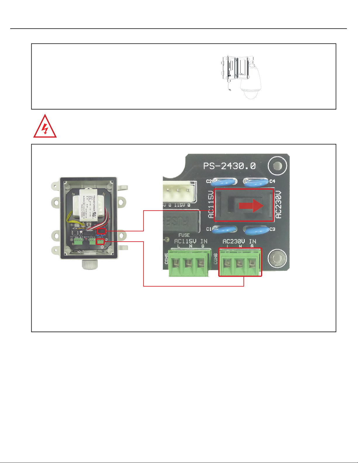
For 110~120VAC VAC Power input connection, connect L(Live), N(Neutral), and G(Ground) power wires to corresponding
screw terminal of AC115V POWER INPUT (part no. 10) on the PS-2430 circuit board, and turn switch(part no.8) on the PS-
2430 circuit board to AC115V.
Part 8
Part 10
For 110~120 VAC Power Input
Connection
2-10
Fix bracket and power block unit with two 6 x 20 hex head
cap screws.
Installation of the CV6XX-DH is now complete.
6 x 20 Hex Head
Cap Screws
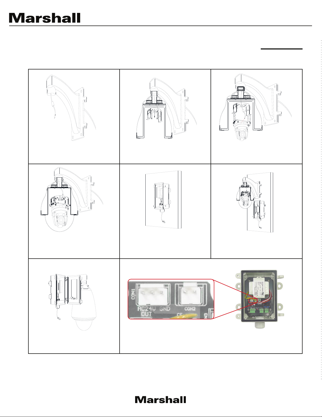
Note:
User only needs to do connections for part 5, 9 or
10 on the PS-2430 circuit board for the power block
unit.
For one heater, total power is 3A (around 72W), fan
and heater consume around 25W.
After fan and heater hooked up and working, there is
47W power available for camera.
* It is advisable to use two heaters in areas which
reach below -25°C. For two heaters, total power is 3A
(around 72W), fans and heater consume around 45W.
After fan and heater hooked up and working, there is
27W power available for camera.
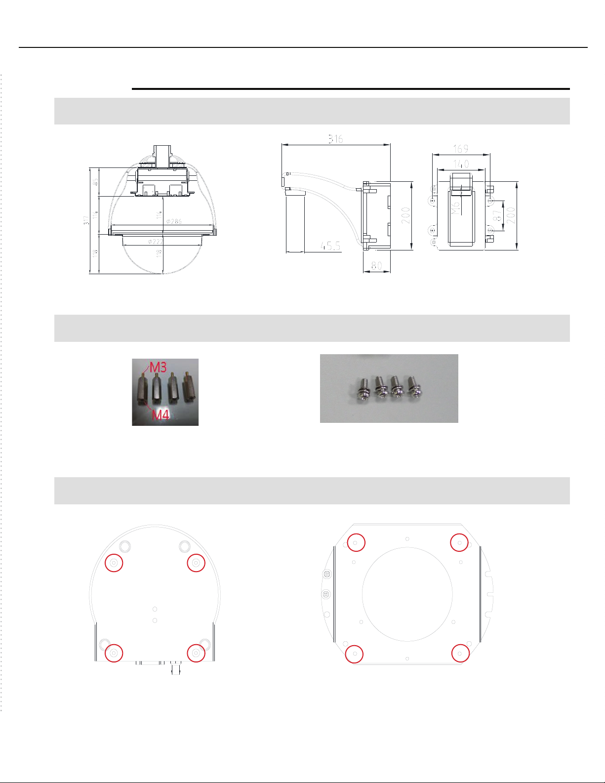
5. Appendix
Dimensions
Component Parts for Assembly
Screws Mounting Position
9” housing
Hexagonal spacers x 4
Position of screw holes on the camera
for fixing hexagonal spacers.
Position of screw holes on the mounting
plate for fixing hexagonal spacers.
Wall mount bracket with power box
M4 x 10 double washer screws