Copyright © 2012 Ron Marston all rights reserved rev. D 2/12
2
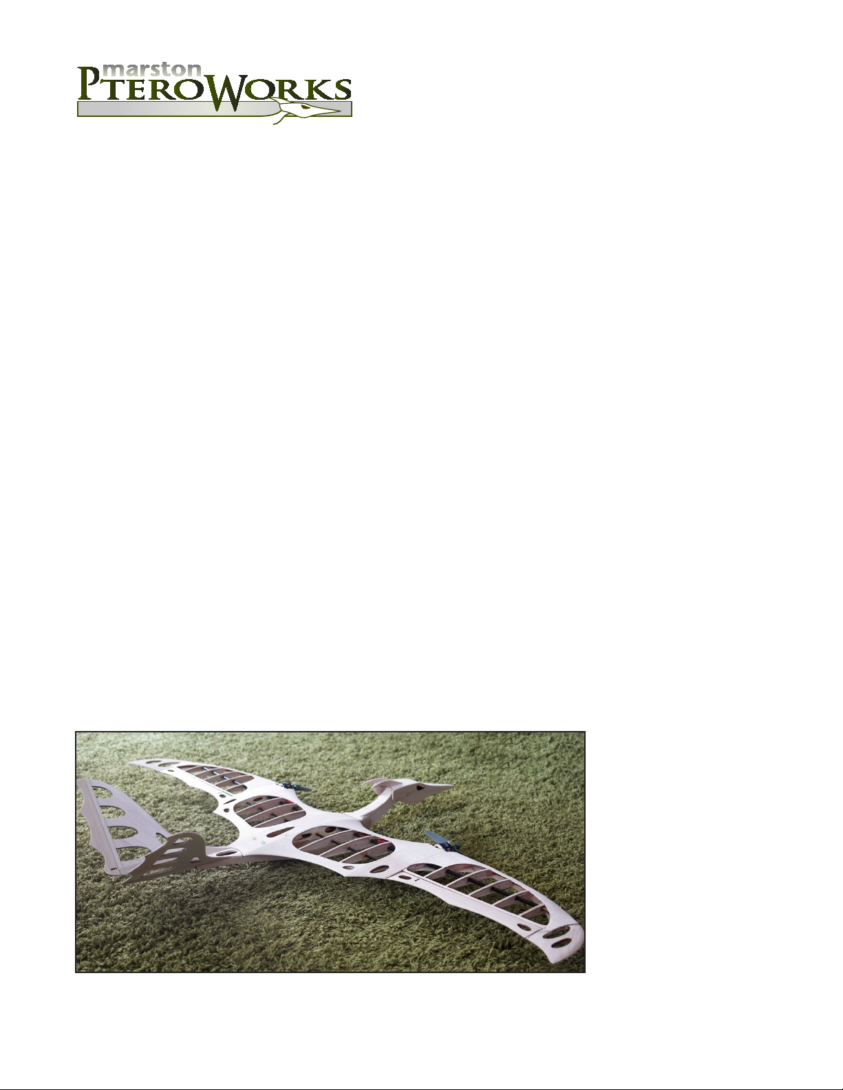
Wing
1. Cut carbon spars to proper length.
forward spar - .240” dia. 41.40”
rear spar - .156” dia. 45.40”
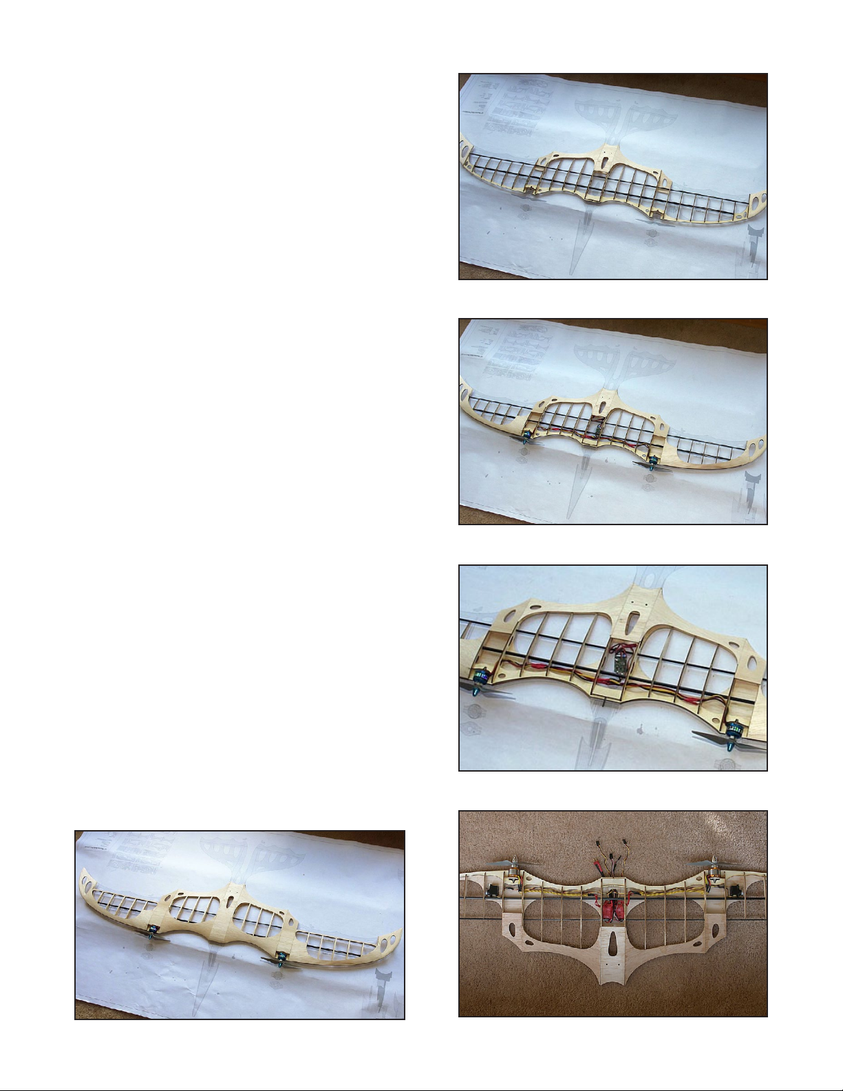
2. Layout all ribs on the plans then carefully feed them
onto the forward spar (.240”).
Do NOT glue yet. (B)
3. Carefully feed rear spar (.156”) onto ribs. Spin spar
as you push to facilitate feeding.
Do NOT glue yet. (C)
4. Attach 4 leading edge pieces. Lay parts on plan to
facilitate alignment. Do NOT glue yet. (C)
5. Glue doubler/connectors to leading edges at the
motor area and at the center of the wing. Then glue
motor mounts after ensuring the hole pattern will
work for your motors. If necessary, use supplied
blank motor mounts and drill appropriate holes for
your motors. Check motor mount incidence angle
for 0 to 1/2 degree of down thrust. (C)
Glue rib (12) in place on left and right sides of wing.
Note: Any twist in the wing should be turned to
create wash-out (trailing edge of wing at tip is
raised compared to trailing edge at root). (D)
6. Glue bottom trailing edge center ply strengthener
along with balsa center bottom trailing edge.
7. Glue remaining bottom trailing edge balsa pieces to
ribs. NOTE: many of the wing sheeting pieces
are different top and bottom. Top pieces are
marked with a “T” and bottom pieces are
marked with a “B”. Assemble with “B”s and “T”s
facing inward to avoid having them show. (D)
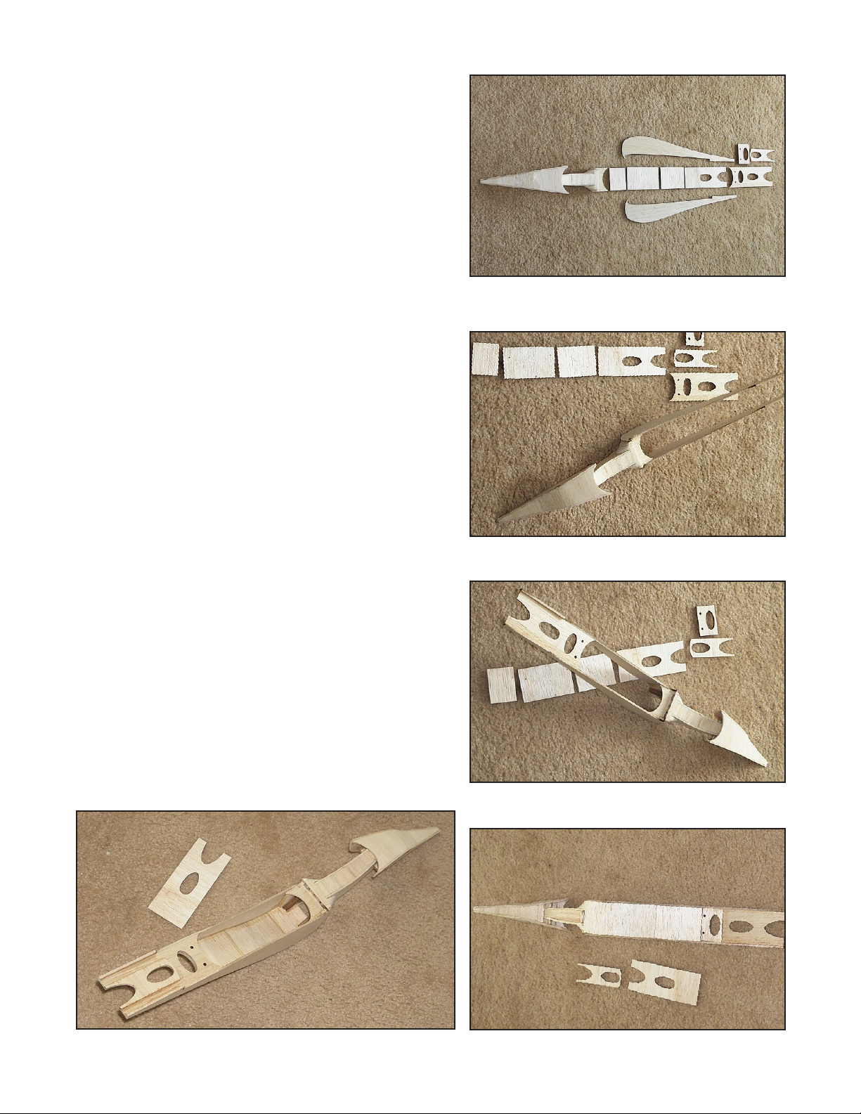
8. Sand rough airfoil into wing tip pieces and glue to
rib 12 on left and right sides. Sand about 5 degrees
into face where it mates with rib 12 so the wing tips
angle up slightly.
9. Lay wing on plans and ensure ribs are in proper
position and that there is no twist in the wing. Use
thin CA and glue all ribs to the carbon spars
and the leading edge pieces.
10. Stack both screw tower pieces together and glue in
place at center trailing edge where the screw holes
are. Sand top to match rib 1 prole. (E)
11. Sand then glue top center trailing edge piece to ribs.
A
B
C
D
E