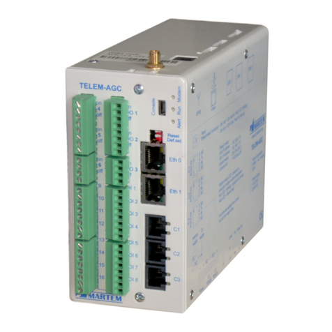
Martem TELEM-GW6 User manual

Data Concentrator TELEM-GW6
User Manual
Martem AS
2010

Contents
1. MAIN TASKS 3
2. POSSIBLE APPLICATIONS 3
3. FEATURES 3
4. VIEW 4
5. TECHNICAL DATA 4
6. TYPICAL APPLICATION FOR ELECTRIC POWER STATION 6
7. SWITCHES 6
8. INDICATION 6
9. FIRMWARE UPDATE 7
10. GW6 CONFIGURATION TOOL 8
10.1 Getting Started 8
10.2 GW6 Configuration Window 9
10.3 Tab Cards in the Configuration Window 10
10.3.1 Ports Tab Card 11
10.3.2 Devices Tab Card 13
10.3.3 Objects Tab Card 15
10.3.4 Formulas Tab Card 19
10.3.5 RTA IO Tab Card 21
10.3.6 Status Tab Card 22
11. COMMON MAIN MENU 23
11.1 Analog Groups 23
11.2 TCP/IP Settings 23
11.3 Timing Settings 23
11.3 Modem Settings 24
11.5 Port Mirroring 24
12. COMMUNICATION CABLES 25
13. NOTES 26

AS Martem Data Concentrator TELEM-GW6 User Manual
Akadeemia tee 21G Tel: +372 639 79 79 E-mail: martem@martem.eu
12618 Tallinn Fax: +379 639 79 80 www.martem.eu
Estonia
- 3 -
1. Main Tasks
The tasks of the Data Concentrator Telem-GW6 (GW6) include the following:
•To control and monitor the system from the control center using data
communication protocols IEC 60870-5-101 and IEC 60870-5-104
•To concentrate data collection from lower level peripheral devices and
control them by using different data exchange protocols
2. Possible Applications
•Data acquisition and control of regional and national electricity utilities in
SCADA systems for remote control and substation automation
•Comprehensive integration of different devices
•As a communication gateway
3. Features
•Telem-GW6 base model includes basic card with built-in communication
ports
•Expansion card 1 and 2 are optional extras (see 5. Technical Data)
•Data concentrator with an associated event annunciator performing sub-
station level master unit functions in the substation secondary equipment
system
•Duplex data communications between the feeder and the equipment level
versus the station control level in substations using different
communication protocols and cross-referencing between the protocols
•Full scale data exchange between the levels of the substation control
system including setting values, measurement values, registered fault
parameter values, changes of state with associated time markings etc
•Data concentrator provided with serial interfaces to facilitate the
connection between local output devices and external host systems
•All the settings can be changed using software configuration tool
•Output channel to the remote control system can be connected to a leased
or a dial-up line using a copper line-, radio- or GSM modem
•Data concentrator GW6 is provided with control input for clock
synchronizing purposes using GPS
•Logical operations between digital and analog signals can be described
•Hierarchical connection is possible
•TELEM RTU devices can be remotely configured across Telem-GW6
•Microsoft Excel direct import and export facilities are in use
•A user-friendly user interface similar to MS

AS Martem Data Concentrator TELEM-GW6 User Manual
Akadeemia tee 21G Tel: +372 639 79 79 E-mail: martem@martem.eu
12618 Tallinn Fax: +379 639 79 80 www.martem.eu
Estonia
- 4 -
4. View
Figure 4 Telem-GW6 view
5. Technical Data
Data communication protocols
•To higher or lower level systems IEC 60870-5-101 or IEC 60870-5-104
•To lower level devices IEC 61850, IEC 60870-5-103, IEC 60870-5-101
Unbalanced, SPA-bus, IEC 62056-21 (IEC 1107), Modbus-RTU

AS Martem Data Concentrator TELEM-GW6 User Manual
Akadeemia tee 21G Tel: +372 639 79 79 E-mail: martem@martem.eu
12618 Tallinn Fax: +379 639 79 80 www.martem.eu
Estonia
- 5 -
Communication ports
Communication ports may be freely configured for upper or lower level
communication
Built-in
•1x Ethernet connection with RJ45 connector
•1x RS-232 full modem serial connection with RJ45 connector
•1x RS-422 serial connection with RJ45 connector
•1x USB connection with Type B connector
Expansion card 1
•1x Fiber-optic connection with ST or Versalink connectors
•1x RS-232 with RTS, CTS handshake signal serial connection with
RJ45 optically isolated connector
•1x RS-485 serial connection with RJ45 optically isolated connector
•1x GPS Fiber-optic connection with Versalink connector
Expansion card 2
•8x RS-232 serial connections with RJ45 connectors
Data communication parameters
•1 start bit
•Odd, even or no parity
•Communication rates from 300 to 115200 bit/sec
•Configurable RTS/CTS handshake for all RS-232 ports.
Electrical characteristics of isolated input
•Dielectric withstand IEC 60255-5
•Withstand to static discharge IEC 61000-4-2
•Withstand to surges, bursts IEC 61000-4-4, 61000-4-5
Mechanical parameters
•Degree of protection IP 32
•Dimensions (W x H x D) ~ 84 x 107 x 164
•Ambient temperature in operation –20…+50°C
•Weight ~ 1kg
•Mounting DIN rail
Power supply
•Supply voltage range 10 to 32 V DC
•Power consumption < 8 VA

AS Martem Data Concentrator TELEM-GW6 User Manual
Akadeemia tee 21G Tel: +372 639 79 79 E-mail: martem@martem.eu
12618 Tallinn Fax: +379 639 79 80 www.martem.eu
Estonia
- 6 -
6. Typical Application for Electric Power Station
7. Switches
1 – Reset: Switch RESET to ON state and then back to OFF state for Reset
operation
2 – Dft. Set: To apply default setup:
1. Switch DFT. SET to ON state
*Alert indication LED starts blinking with 5 second interval
2. Switch DFT. SET back to OFF state when the alert indication LED is
blinking to apply default setup
*If DFT. SET is switched back to OFF state at a moment when the alert
indication LED is not blinking, default setup will NOT be applied
8. Indication
For operation
Green LED – Blinking green indicates that the program is running
Red LED – Failure
For communication
Yellow LED – RX
Green LED – TX
Green LED at GPS port – blinking indicates the existence of GPS time
synchronization.
Reset
Dft. set

AS Martem Data Concentrator TELEM-GW6 User Manual
Akadeemia tee 21G Tel: +372 639 79 79 E-mail: martem@martem.eu
12618 Tallinn Fax: +379 639 79 80 www.martem.eu
Estonia
- 7 -
9. Firmware Update
Loading GW6 firmware is done through Secure Digital (SD) Memory Card
slot.
Updating firmware:
1. Connect Secure Digital (SD) Memory Card to your computer
2. Extract the compressed firmware update file (provided by Martem AS)
to your SD Memory Card
3. Disconnect the card from your computer
4. Insert the card to Telem-GW6 SD Memory Card slot
* SD Memory Card slot is located at the back of the device
5. Perform reset operation to Telem-GW6 device
6. Wait until the device resumes to it’s normal operation state
7. Firmware update is complete. Remove the SD Memory Card and check
if firmfare update was successful
Checking results of the firmware update operation:
1. Connect the SD Memory Card to your computer
2. Open the folder you extracted earlier
3. Check if the file “res.txt” is present and open it
4. Check the state of installed files at the last part of the file
*If the state of update files is OK - firmware update was successful

AS Martem Data Concentrator TELEM-GW6 User Manual
Akadeemia tee 21G Tel: +372 639 79 79 E-mail: martem@martem.eu
12618 Tallinn Fax: +379 639 79 80 www.martem.eu
Estonia
- 8 -
10. GW6 Configuration Tool
10.1 Getting Started
When starting the GW6 configuration program, user interface window with the
main menu is opened:
Figure 10. 1.1 User interface window
The following parameters are shown for information:
•Port – PC port which is used to communicate with GW6
•Link address – Link address of GW6
•ASDU address – ASDU address of GW6
•Status –Status of the connection. RED – no connection, GREEN –
connection OK
Main menu
•Device –For selecting the device type
•Communication Setup - For changing communication parameters.
Figure 10.1.2. Communication parameters window

AS Martem Data Concentrator TELEM-GW6 User Manual
Akadeemia tee 21G Tel: +372 639 79 79 E-mail: martem@martem.eu
12618 Tallinn Fax: +379 639 79 80 www.martem.eu
Estonia
- 9 -
Fields in the communication parameters window
•Port – PC communication port which is used to communicate with GW6
•Baud rate – Data communication rate
•Parity – Use of parity control bit
•
Flow control – Determines whether the RTS/CTS handshaking is used
•Communication delay – Delay between reception of data and the next
query in milliseconds
•Link address – Link address of GW6
•ASDU address – ASDUI address of GW6
•ASDU address length – The length of the ASDU address in bytes:
typically 2, possible values are 1 or 2.
•Object address length – Length in bytes. Typically 2, possible values are
1, 2 or 3.
10.2 GW6 Configuration Window
To open the GW6 configuration window, select Device > GW6 / RTA-A from
the user interface main menu.
Shortcut icons below the menu bar:
Open a new configuration
Open a configuration file
Save the configuration to a file
Read the configuration from GW6
Write the configuration to GW6
*Reset GW6
* Possible Reset codes:
1 – Simple Reset
2 – Reset that also clears memory buffers
3 – Reset that also restores the default setup
Saving, editing and opening configuration data
Configuration data is saved to the hard disk in the form of comma separated
files*.CSV files when the Save or Save As command is chosen from the File
menu. Correspondingly, the Open command from the File menu opens this
type of file. Open and Save can also be accessed via shortcut icons.
*.CSV files can be conveniently edited with Excel software or even with the
Note Pad program. When editing the configuration with Excel, the file has to
be saved as a comma separated CSV file.

AS Martem Data Concentrator TELEM-GW6 User Manual
Akadeemia tee 21G Tel: +372 639 79 79 E-mail: martem@martem.eu
12618 Tallinn Fax: +379 639 79 80 www.martem.eu
Estonia
- 10 -
Table of configuration window menu items
Main menu File Common View Help
Submenu
(Shortcut key)
New (Ctrl+N)
Read
Configuration Basic Help (F1)
Open(Ctrl+O) Write
Configuration Advanced About
Save (Ctrl+S) Cancel Active
Transfer
Save As Send Reset
Exit Analog
Groups
Tcp/Ip
Settings
Timing
Settings
Modem
Settings
Port Mirroring
Options
10.3 Tab Cards in the Configuration Window
Configuration and setting parameters can be utilized by using topic tab cards:
Ports, Devices, Objects, Formulas, RTA IO, Status.
A click on a tab card button switches between tab cards.
Using the grid area
Parameters can be selected or changed in the grid area cells. Values of some
cells can be changed directly and those of others via a list box or a popup
window.
Values of the same column can be copied to clipboard. Use a left mouse click
together with the Shift key to copy and a left mouse click together with the Ctrl
key for paste operation.
Status message in the bottom left corner of the window shows the result of the
last data modification action (OK, Error, etc).

AS Martem Data Concentrator TELEM-GW6 User Manual
Akadeemia tee 21G Tel: +372 639 79 79 E-mail: martem@martem.eu
12618 Tallinn Fax: +379 639 79 80 www.martem.eu
Estonia
- 11 -
10.3.1 Ports Tab Card
Ports/configuration tab card (Figure 10.3.1) is active when the GW6
configuration window is opened.
From the View menu a Basic or an Advanced view of the Port
configuration tab card can be selected. The Advanced view shows the
additional query and echo suppression parameters.
Figure 10.3 .1 Configuration window with an advanced Port configuration tab
card
Configuration parameters of a port:
•Protocol – Communication protocol used by all the devices of this port.
Each protocol name is accompanied with a symbol l”^” or ”ν” which
indicates whether the port is used for an uplink or a downlink channel. For
example, “Modbus ν” means that this port is used for downlink with
Modbus protocol.
•Baud rate – Data communication rate
•Parity – Use of parity bit for all the devices on this channel
•Stop Bit – possible values are 1, 2
•Data Bits – possible values are 7, 8

AS Martem Data Concentrator TELEM-GW6 User Manual
Akadeemia tee 21G Tel: +372 639 79 79 E-mail: martem@martem.eu
12618 Tallinn Fax: +379 639 79 80 www.martem.eu
Estonia
- 12 -
•Communication Mode – Makes it possible to choose between the
following handshaking options:
- No control
- Modem Callout – Port 2
- RTS/CTS Control – Port 2
- RS-485 – Port 5
- Tcp/IP – Beginning from Port 14
•IP address – communication IP address (used if Communication Mode is
set to Tcp/IP)
IP Address – an address of the device that
communicates with GW6 using
corresponding port
Interface IP Address – address of GW6
Port – available network communication port
(in case of IEC 60870-5-104 protocol, prot
2404 is recommended)
•Polling(v)/Answering(^) Delay – Delay
between reception and the next query
•Port Link Address – Link address of the device on uplink channels
•IEC ASDU Address – ASDU address on uplink channels
•Length of the ASDU Address – Length of the ASDU address in bytes on
uplink channels. Typically 2, possible values are 1 or 2
•IEC Object Length – Length of the IEC object address in bytes on uplink
channels. Typically 2, possible values are 1, 2
•Up Protocol Subversion – Number of protocol subversion on uplink
channels
More on the advance view:
•Query Timeout [ms] – Query timeout for devices on downlink channels
•Failed Query Count for disabling contr. – Count of timeouts after which
the error flag is raised and the query of this device temporarily suspended
•Query Interval for Retry/Bal.mode [s] – Time period after which the
suspended device is queried again
•Suppress Echo – If the sent messages are echoed back by the
connected devices then they need to be suppressed
If some parameters in the grid area have a grey background then these are
not used for the chosen protocol type but you are still allowed to modify them.

AS Martem Data Concentrator TELEM-GW6 User Manual
Akadeemia tee 21G Tel: +372 639 79 79 E-mail: martem@martem.eu
12618 Tallinn Fax: +379 639 79 80 www.martem.eu
Estonia
- 13 -
10.3.2 Devices Tab Card
Figure 10.3.2. Devices tab card
Parameters:
•Device nr – Sequence number of the device
•Objects – Number of objects in the device
•Link address – Link address of the connected device
•ASDU address – ASDU address of the connected device
•ASDU address length – Length in bytes, possible values are 1 or 2
•Object address length – Length in bytes, possible values are 1, 2 or 3
•In use – Indicates whether the device is in use or not. If the device is not in
use, the whole row has a grey background
•Port – Port no. of GW6 to which the device is connected
•Protocol Subversion – Number of protocol subversion
•Protocol – For information only. It is filled automatically according to the
number of the used port.
•Minute Time Sync – Yes/No. If Yes, the device is synchronized with 10
second period
•Time Sync Forward – Yes/No. If Yes, the time synchronization which is
received from upper channel, it is forwarded to the device
•Replace Event hrs – Yes/No. If Yes, events are sent to control centre with
UCT time (the time correction value is set in Common Menu, Timing
Settings)

AS Martem Data Concentrator TELEM-GW6 User Manual
Akadeemia tee 21G Tel: +372 639 79 79 E-mail: martem@martem.eu
12618 Tallinn Fax: +379 639 79 80 www.martem.eu
Estonia
- 14 -
•Control takeover addr.^ – The address of an object which determines
control takeover of that device
•Signals blocking addr.^ – The address of an object which determines
blocking of all signals from that device. No signals are sent to control
centre from that device
Adding devices
By clicking on the shortcut icon, a new device with default settings is
added. It is also possible to add new devices with a right mouse click which
makes the extended control menu to appear.
Add Devices dialog box appears.
Set the Add Devices options:
- Number of devices to add
- Default settings or the
device number from where
the settings are derived
- Copy Object Also
Click the Add button.
Removing Devices
To remove a device, select Remove Devices from the extended control menu
or click on the shortcut icon.
Select the range of the removed devices and click the Remove or Remove
All button. The selected device is also removed after the warning dialog when
is clicked.

AS Martem Data Concentrator TELEM-GW6 User Manual
Akadeemia tee 21G Tel: +372 639 79 79 E-mail: martem@martem.eu
12618 Tallinn Fax: +379 639 79 80 www.martem.eu
Estonia
- 15 -
Clearing Devices
To clear the Device Tab Card, select Clear from the extended control menu.
A warning window always appears before removing operations are concluded:
Select Yes to accept or No to cancel the removal operation of the devices.
10.3.3 Objects Tab Card
Figure 10.3.3 Objects tab card
The first object of every device is used as the communication status signal of
the device. If its value is “1” then communication with this device is broken.
The object (first object) of communication status signal is not counted in the
Objects row of the Devices Tab Card.

AS Martem Data Concentrator TELEM-GW6 User Manual
Akadeemia tee 21G Tel: +372 639 79 79 E-mail: martem@martem.eu
12618 Tallinn Fax: +379 639 79 80 www.martem.eu
Estonia
- 16 -
Columns:
Type – Object’s type: digital input (DI), digital output (DO), analog input (AI),
counter (CN)
Sub Type^ – Object’s subtype for uplink. The following dialog box opens on
clicking:
Subtypes of object and time marking mode can be selected.
Sub Type v – Object’s subtype for downlink. The following dialog box opens
on clicking:
Object
type Format Time marking
DI –
Digital
input
Single
Double Without time
With Short Time
With Long Time
With Short Time if got with time tag
With Long Time if got with time tag
DO –
Digital
output
Single
Double
Direct Execute
Select Execute
AI –
Analog
input
Normalized
Floating point
Step position
Without time
With Short Time
With Long Time
With Short Time if got with time tag
With Long Time if got with time tag
CN –
Counter

AS Martem Data Concentrator TELEM-GW6 User Manual
Akadeemia tee 21G Tel: +372 639 79 79 E-mail: martem@martem.eu
12618 Tallinn Fax: +379 639 79 80 www.martem.eu
Estonia
- 17 -
•Invert – Object’s value will be inverted
•Fn.code – Function code on the IEC 60870-5-103 protocol
•Info no. – Information number on the IEC 60870-5-103 protocol
•Index – Object index on the IEC 60870-5-103 protocol. It indicates the
order number of the object in message types 3 and 9 of analog
measurements.
•Object.Addr ν– Object’s downlink address
•61850 v – 61850 address (selected from drop-down menu)
•Object.Addr ^ – Object’s uplink address
•DB1 %Fs – Deadband (% of full scale). If the value has changed less
than the deadband then it is not spontaneously transferred.
•DB2 %Fs – This is used instead of DB if the Crit.Min and Crit.Max
fields are used and the value falls within these limits. In case of offline
(GSM) channel, if the change in value is bigger than deadband 2 (% of
full scale) then a call to SCADA system is initiated.
•Raw Min, Raw Max – Minimum and maximum raw values of analog
measurement (before scaling).
•Scale Min, Scale Max – Minimum and maximum scale values of
analog measurement.
•Forb. Ports – Uplink port to which the object’s value transfer is
blocked. To select uplink ports, which should not be used for
transferring these object values, double-click on the cell of the Forb.
Ports column and select the corresponding ports from the window that
has appeared.
•Crit.Min %Fs / On Ev. Nr; Crit.Max %Fs / Off Ev. Nr
Crit.Min %Fs; Crit.Max %Fs – Minimum and maximum values in %
from the full scale of analog measurements on which GW6 initializes
communication (Fig. 10.5.1). If Crit. Max and Crit. Min do not have
values, DB1 and DB2 are in use. If Crit. Max and Crit. Min have the
value ‘zero’, only DeadB1 is in use. If the analog measurement value is
between Crit. Min and Crit. Max, DB2 is in use. If the analog
measurement value is out of limits, DB1 is in use.
On Ev. Nr; Off Ev. Nr – Corresponding event number used in SPA-bus

AS Martem Data Concentrator TELEM-GW6 User Manual
Akadeemia tee 21G Tel: +372 639 79 79 E-mail: martem@martem.eu
12618 Tallinn Fax: +379 639 79 80 www.martem.eu
Estonia
- 18 -
•Forb. Calling – Block object’s value transfer.
•Ch. Nr. – Channel nr. for SPA-bus communication protocol
•noFlags – If set to Yes, removes Invalid and Not Topical flags from
object status. Used for objects, which statuses are not received with
General Interval time (short circuit current, etc.)
Adding Objects
By clicking on the button, a new device with default settings is added.
Objects can also be added with a right click on the device tab card. After that
the following extended control menu appears:
When selecting Add Objects, the following dialog box appears:
Removing Objects
To remove a device, click the button or select Remove Devices from the
extended control menu. The following dialog box appears:

AS Martem Data Concentrator TELEM-GW6 User Manual
Akadeemia tee 21G Tel: +372 639 79 79 E-mail: martem@martem.eu
12618 Tallinn Fax: +379 639 79 80 www.martem.eu
Estonia
- 19 -
Hints
•Repeated object addresses are shown on yellow background.
•When leaving the Object Tab Card, all the objects are hidden. To see
the objects on returning to Object Tab Card, use Expand All from the
extended control menu that appears after a right click.
10.3.4 Formulas Tab Card
Figure 10.3.4 Formulas tab card
Columns:
•Type, Sub Type , Invert, Object Adr ^, DB1 %Fs, DB2 %Fs, Crit.
Min %Fs, Crit. Max %Fs, Raw Min, Raw Max, Scale Min, Scale
Max, Forb.Ports - as in Objects Tab Card
•LED no – The alarm (LED) number (1…16) on the LED Alarm panel
which corresponds with the result of this formula
•DO addr. – Number of the digital output (1…16) in the TLM GW-IO
device controlled by the result of this formula
•Execution count – The number of control operations executed, if no
feedback is received from control relay. Feedback must be determined
in the formula
•Delay – Delay for execution in seconds
•Forb. DO – The number of DO, which control is forbidden with the
result of this formula
•LED Blinking – Determines if the LED that indicates the result of this
formula, remains blinking when corresponding signal disappears. The
LED remains blinking until the acknowledge button is pressed
•Formula – Formula string

AS Martem Data Concentrator TELEM-GW6 User Manual
Akadeemia tee 21G Tel: +372 639 79 79 E-mail: martem@martem.eu
12618 Tallinn Fax: +379 639 79 80 www.martem.eu
Estonia
- 20 -
Editing formulas
Formulas can be created between the values of analog and/or digital objects.
Referencing to object values
To use the measurement object in the formula, insert an @ sign together with
the object address up.
Example: @101 points to the value of the object with an address to uplink
101.
Constants
Constants can be used in formulas.
Example: 1.1+2.2+3 consists of 3 floating point constants
Brackets
Brackets can be used in formulas to change the priority of the operation.
Example: sqrt(@101/2+@102); (@201+@202+@203)/3
Operators
Oper.
Obj. type
Description
Sampl
e
*Priority
+ DI/AI Addition @101+3,2 3
- DI/AI Subtraction @101-0,49 3
* DI/AI Multiplication @101*2 2
/ DI/AI Division @101/2 2
^ DI/AI Exponentiation @101^2 1
< DI Greater than @101<0,499 4
> DI Less than @101>0,5 4
sqr DI/AI Square sqr(@101*10) 0
sqrt DI/AI Square route sqr(@101*10) 0
and DI Logical conjunction @201and@202 5
or DI Logical disjunction @201or@202 6
xor DI Exclusive disjunction @201xor@202 6
not DI Logical negation not@201 0
dbl DI Converts 2 single digital
inputs into a double signal @201dbl@202 7
sin DI/AI sin@301 0
cos DI/AI cos@301 0
tan DI/AI tan@301 0
arcsin DI/AI arcsin@301 0
arccos DI/AI arccos@301 0
arctan DI/AI arctan@301 0
* priority determines the order of operations in the formula (the highest priority
is 0)
Table of contents
Other Martem Network Hardware manuals
Popular Network Hardware manuals by other brands

Memotec
Memotec NetPerformer SDM-9120 Series Hardware installation guide

Wybron
Wybron Transition Optic user manual

Ruijie
Ruijie Reyee RG-EST Series Configuration guide

SAB
SAB SABVISION NVR32 quick start guide

Avalue Technology
Avalue Technology UB-T100 Quick reference guide

C&H
C&H Active Module Carrier VX402C-64 user manual

Fluke
Fluke TAP-T1E1 Quick installation guide

Enterasys
Enterasys RoamAbout RBTBH-R2W installation guide

Clearfield
Clearfield Home Deployment Kit installation manual

ADTRAN
ADTRAN DSU 56/64 user manual

Western multiplex
Western multiplex Tsunami 27200-G1 Series Installation and maintenance manual

Vivotek
Vivotek ND8301 Quick installation guide