Martin Audio DX0.6 User manual

DX0.6 User
Guide
Loudspeaker management
system

Copyright © 2024 Martin Audio Limited
Publication date 2024-02-23
Important safety instructions
▪Please read these instructions and keep them for
future reference.
▪Heed all warnings and follow all instructions.
▪Keep this unit away from rain or moisture.
▪Keep this unit away from heat sources.
▪Keep this unit away from candles and flames.
▪Don't block the ventilation openings.
▪Install in accordance with Martin Audio instructions.
▪Don't remove the protective earth from the power
cable plug. This unit must be earthed.
▪Protect the power cable from being walked on or
damaged, particularly near the plugs.
▪Unplug this unit during lightning storms or when
unused for a long period of time.
▪Don't open this unit. There is a risk of electric shock
and there are no user-serviceable parts.
▪If servicing is required, contact qualified service
personnel.
▪At the end of this unit's life, please use a recycling
centre.

Table of Contents
Introduction ............................................................................................................................................ 5
Features ......................................................................................................................................... 5
Getting started ........................................................................................................................................ 6
Desktop app .................................................................................................................................... 6
Connecting your processor and computer ........................................................................................... 6
Setting up using the front panel ......................................................................................................... 7
Connecting your system ................................................................................................................... 7
Remember ...................................................................................................................................... 7
Front panel ............................................................................................................................................. 8
Back panel .............................................................................................................................................. 9
Utility menu .......................................................................................................................................... 10
To use the utility menu .................................................................................................................... 10
Utility menu choices ....................................................................................................................... 10
System utilities ...................................................................................................................................... 11
Input source .................................................................................................................................. 11
Signal generator ............................................................................................................................ 11
Link input ..................................................................................................................................... 12
Link output ................................................................................................................................... 12
Linked channel mode ..................................................................................................................... 12
Recall mode .................................................................................................................................. 13
Set factory value ............................................................................................................................ 13
Prevent output clip ........................................................................................................................ 13
Output vu-meter ............................................................................................................................ 14
Firmware version ........................................................................................................................... 14
Program utilities .................................................................................................................................... 16
Recall a program ........................................................................................................................... 16
Save a program ............................................................................................................................. 16
Network utilities .................................................................................................................................... 17
RS-485 ID ..................................................................................................................................... 17
Device name ................................................................................................................................. 17
IP address ..................................................................................................................................... 17
Subnet mask ................................................................................................................................. 18
Gateway ....................................................................................................................................... 18
LAN mode ..................................................................................................................................... 18
Security utilities ..................................................................................................................................... 20
To log in as Admin or Expert ............................................................................................................ 20
To log out ...................................................................................................................................... 20
Input channels ...................................................................................................................................... 21
To edit the input channels ............................................................................................................... 21
Input channel menu ....................................................................................................................... 21
Input name ................................................................................................................................... 21
Input noise gate ............................................................................................................................. 22
Input gain ..................................................................................................................................... 22
Input polarity ................................................................................................................................. 22
Input delay .................................................................................................................................... 23
Enable input EQ ............................................................................................................................. 23
Ten band input EQ ......................................................................................................................... 23
Output channels .................................................................................................................................... 25
To edit the output channels ............................................................................................................. 25
DX0.6 User Guide
3

Output channel menu ..................................................................................................................... 25
Output name ................................................................................................................................. 25
Resetting a channel to factory defaults ............................................................................................. 26
Output source ............................................................................................................................... 26
Output gain ................................................................................................................................... 26
Output polarity .............................................................................................................................. 27
Output delay ................................................................................................................................. 27
Peak limiter ................................................................................................................................... 27
Program limiter .............................................................................................................................. 27
Output FIR enable .......................................................................................................................... 28
High pass filter .............................................................................................................................. 28
Low pass filter ............................................................................................................................... 28
Enable output EQ ........................................................................................................................... 29
Eight band output EQ ..................................................................................................................... 29
Example systems ................................................................................................................................... 30
BlacklineX12 and X118 subs ........................................................................................................... 30
O-Line arrays and SX112 subs ......................................................................................................... 30
Two pairs of LE200 monitors ........................................................................................................... 31
CDD12, CDD6 and SX212 subs ....................................................................................................... 31
THV and SX118 subs ...................................................................................................................... 32
BlacklineX12 and SCX115 subs ....................................................................................................... 32
Troubleshooting ..................................................................................................................................... 34
No power ...................................................................................................................................... 34
Noise or hum ................................................................................................................................. 34
No sound ...................................................................................................................................... 34
One side is louder than the other ..................................................................................................... 34
Bad sound .................................................................................................................................... 34
Technical specifications ......................................................................................................................... 35
DX0.6 User Guide
4

Introduction
The DX0.6 is a digital audio processor with an extremely
low noise floor, high dynamic range and powerful internal
DSP. It delivers excellent performance in meeting rooms,
small theaters and clubs.
The DX0.6 uses powerful custom Digital Signal
Processing and an original DSP algorithm. The DSP and
AD/DA run at 96KHz sampling rate. The DX0.6 offers
a complete processing and crossover solution for any
loudspeaker system. We have two models in this range,
the DX0.4 with four outputs and the DX0.6 with six
outputs. The number of outputs is is the only difference
between these two models.
The comprehensive signal chain features input gain,
delay, noise gate, EQ and routing, to output gain, delay,
polarity, cross-over, EQ, Program and Peak limiters. There
are a remarkable 14 types of parametric equalizer (PEQ).
The output crossover filter includes the classic Linkwitz-
Riley, Bessel and Butterworth filter styles with slopes from
6dB/octave up to 48dB/octave.
The newly designed limiter section maintains a maximum
level over a slow time constant to restrict the long-
term power applied to your speakers. This reduces the
possibility of damage and also allows for the short term
peaks that are an essential component of any program
material. A second limiter restricts short term peaks to
a safe level for the speakers thus providing the best
possible solution to keep your sound system working
faultlessly.
Each output offers the option to import a maximum 512-
taps FIR filter. Used for speaker presets, it can improve
the phase response and control the directivity according
to your requirements.
Features
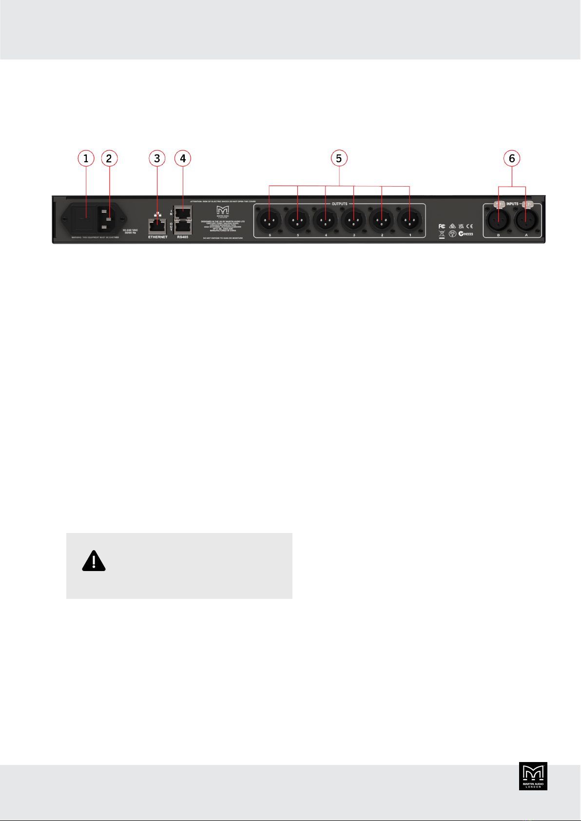
▪Professional 2-input, 6-output system processor for a
wide range of system applications.
▪Comprehensive, sophisticated processing options
including EQ, gate, delay and limiting to optimise and
protect a system.
▪Fully assignable matrix routing of both inputs to any
output with attenuation option on each routing node.
▪Two balanced XLR inputs with up to 12dB of gain,
polarity invert, 600ms of delay, 10 band parametric EQ
with a choice of 14 filter types individually selectable
for each band.
▪Six impedance balanced XLR outputs with 12dB of
gain, polarity invert, 200ms delay, high and low pass
filters with cut-off slopes from –6dB/oct to –48dB/oct
using either Bessel, Butterworth or Linkwitz-Riley
filters. 8 band parametric EQ with up a choice of 14
filter types, Independent Program and Peak Limiters.
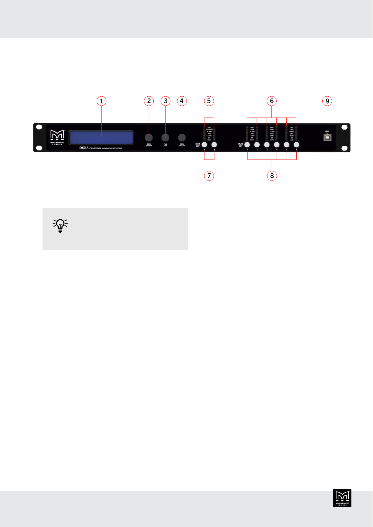
▪Convenient front panel controls and LCD display for
setting or modifying settings. One press mute buttons
for all inputs and outputs.
▪Front panel USB port for quick and easy PC
connection.
▪Networking option using either Ethernet or RS485 for
larger systems.
▪Output channel preset import function to quickly and
easily import a library of output channel presets for
Martin Audio loudspeakers.
▪Six segment LED metering for input and output level
and limiter operation.
▪32 User Presets to store system configurations.
▪Three-level customisable user modes with individual
password protection.
▪Universal switch mode mains PSU accepts 90 to 240V,
50/60Hz.
▪Compact 1 rack unit design.
▪Approximate shipping weight: 3.5kg.
DX0.6 User Guide
5

Getting started
There are two ways to set up your DX0.6. You can:
▪Use a desktop app running on a computer connected
to your DX0.6. This allows you to access all of the
settings and is usually the easiest and best way to set
up your processor. You can also use this to control your
processor remotely.
▪Use the buttons and screen on your DX0.6. This allows
you to do a quick update to your settings without the
need to connect a computer. You can access most but
not all of the settings.
You could use a combination of these
methods. For example, you could set
up the DX0.6 initially using the desktop
app. Then later you could update
settings using the buttons and screen on
the DX0.6.
Desktop app
The desktop app is a Windows app available as a free
download from the Martin Audio website.
We don't support macOS, but some
users have run this app successfully
on a virtual platform such as Parallels
Desktop, VMware Fusion or Apple Boot
Camp Assistant.
To set up your DX0.6 using this desktop app, you need
to install the app and connect your processor to your
computer.
To install the desktop app
1. Go to the Martin Audio website and select Support >
Software.
2. Select and download the DX0.4 and DX0.6 Control
Software.
3. Follow the instructions bundled with the software.
Connecting your processor and
computer
There are four ways of connecting your processor to your
computer:
▪USB. Use a USB cable to connect the USB-B port on
the front panel of your processor and a USB port on
your computer.
You can only connect one processor
at a time with USB.
▪Ethernet direct. Use a network cable to connect the
Ethernet socket on the back panel of your processor
directly with the Ethernet socket on your computer.
You can only connect one processor
at a time with a direct Ethernet
connection.
▪Ethernet network. Use a network cable to connect the
Ethernet socket on the back panel on your unit to the
same Ethernet network as your computer.
You can set up and control as
many processors as you like with an
Ethernet network.
▪RS-485. Use an RS-485 cable to connect the RS-485
socket on the back panel of your unit and your
computer. Very few PCs have an RS-485 socket, so
you will almost certainly need an RS-485 RJ45 to USB
adaptor. These are readily available and inexpensive.
RS-485 networks are highly robust and the cable runs
between devices can be up to 1,200 meters. If you
have several units, you can daisy chain them using the
two RS-485 ports on the back panel of each unit.
You can set up and control up to 32
processors with RS-485.
DX0.6 User Guide
6

Dynamic or static IP
With an Ethernet network, you can choose dynamic or
static IP:
▪With dynamic IP a DHCP Server allocates IP Addresses
for all devices on the network. For up to about five
processors, we recommend dynamic IP. A Wi-Fi router
is a good option for small systems, as the router will
include a DHCP Server and you could connect your
computer to the router using Wi-Fi.
▪With static IP you need to specify the IP of each
device manually. Static IP is particularly useful for large
systems with many processors.
To select dynamic or static IP, use the desktop
app (page 6). You can't change this at the front panel
of the processor.
Setting up using the front panel
To set up your DX0.6 using the buttons and screen on the
front panel, you need to:
▪Configure the main settings using the Utility menu. For
details, see Utility menu (page 10).
▪Configure the input channels. For details, see Input
channels (page 21).
▪Configure the output channels. For details, see Output
channels (page 25).
Connecting your system
For example system configurations, see Example systems
(page 30).
1. Before you connect your equipment, make sure that
everything is switched off and the master volume,
level or gain controls are all the way down.
2. Connect the line-level outputs from your mixing
console (or other signal source) to the inputs of your
DX0.6.
3. If you're using amplifiers, connect the outputs from
your DX0.6 to the inputs of your amplifiers. Connect
the outputs from your amplifiers to the inputs of your
passive loudspeakers.
If you're using powered loudspeakers, connect the
outputs from your DX0.6 to the inputs of your
speakers.
4. Turn on the mixing console (or other signal source).
5. Turn on your DX0.6.
6. Configure the system setup to match your
loudspeaker system. See Getting started (page 6).
7. Un-mute the appropriate outputs on your DX0.6.
8. Turn on your amplifiers or powered loudspeakers.
Turn up the volume or gain control. In most
circumstances, you should turn the gain controls up
to maximum so that the amplifier gain matches the
limiter threshold levels of the the DX0.6.
9. Start the signal source and raise the mixer’s main
L/R faders up until you can hear audio through the
loudspeakers.
Remember
▪When you shut down your equipment, turn off the
amplifiers first. This is to prevent thumps and other
noises generated by upstream equipment from coming
out of the speakers.
▪When powering up your equipment, turn on the
amplifiers last.
▪Don't listen to loud music for prolonged periods.
DX0.6 User Guide
7

Front panel
1. The LCD display allows you to view and update the
settings on your processor.
You can also set up your processor
using a desktop app. For details, see
Desktop app (page 6).
2. PM1/ENTER. This is a rotary dial that also acts as a
push button. To scroll through menus, you rotate this
dial left or right. To select a menu item, you press this
dial. From now on we will refer to this as PM1.
3. PM2/ESC. This is also a rotary dial and push button.
To edit items, you rotate this dial left or right. To
escape from the current menu selection, you press
this dial. From now on we will refer to this as PM2.
4. PM3/UTILITY. This is also a rotary dial and push
button. To edit items, you rotate this dial left or right.
To select the utility menu, you press this dial. From
now on we will refer to this as PM3.
5. Input meters. Each input has a bar graph of LEDs that
acts as a meter:
▪OVER (red) signal level exceeding maximum and
clipping.
▪+12dBu (yellow) signal level over +12dBu.
▪0dBu (green) signal level over 0dBu.
▪-12dBu (green) signal level over -12dBu.
▪SIG (green) signal present minimum -40dBu.
▪Mute (red) channel muted. No levels will appear in
the LEDs above.
6. Output meters. Each output has a bar graph of LEDs
that acts as a meter. These meters are the same as
the input meters except that there are two red LEDs at
the top rather than one:
▪LIMIT (red) signal level exceeding maximum. Peak
limiter operating.
▪OVER (red) signal level exceeding maximum.
Program limiter operating.
7. Input buttons. These are labelled A and B. Each
button is a mute button and an edit button:
▪To mute an input, press the appropriate button
quickly. The mute LED will light up red. To un-
mute, press the button quickly again. The red light
will go out.
▪To edit an input, press and hold the button until it
lights up blue. To stop editing, press PM2.
For details of editing inputs, see Input channels (page
21).
8. Output buttons. These are labelled 1 to 6. Each
button is a mute button and an edit button and these
buttons work in exactly the same way as the input
buttons.
For details of editing outputs, see Output channels
(page 25).
9. USB-B socket. You can use this to connect your
processor to a computer. Alternatively, you can use
the Ethernet or RS485 sockets on the back of your
processor. For details, see Connecting your processor
and computer (page 6).
DX0.6 User Guide
8

Back panel
1. Power. To turn the unit on, plug it in and press this
switch to "I". To turn it off, press this switch to "O".
When the unit is on, the LCD display on the front
panel lights up.
This unit remembers any setting changes, so when
you switch the unit on, the unit restarts with the same
settings as when you switched it off.
The unit uses relays on the outputs to prevent
unwanted pops and noise in the system when you
switch it on and off. When you switch it on, the unit
initializes and the relays switch. Any live outputs will
smoothly fade from silence to the configured output
levels.
2. Power lead socket. This IEC input is where you plug
in the detachable power cable supplied with your
processor. Plug the other end into an AC outlet. If the
cable has the wrong mains plug, either use a safety
approved IEC cable with the correct plug or ask a
qualified electrician to change the plug. Note that
the power cable has live, neutral and earth (ground)
connected.
Don't disconnect the earth
connection. This could be
dangerous.
The processor can accept voltages from 100V to
240V AC at frequencies of 50 to 60Hz. You don't need
to adjust anything on the unit.
3. Ethernet. The Ethernet port is a standard RJ45 port.
This allows you to connect to an Ethernet network
with dynamic or static IP. For details, see Connecting
your processor and computer (page 6).
As with most Ethernet ports, there are two LEDs that
show the connection state and the network activity.
4. RS485. The upper RJ45 port (labelled IN) allows
you to connect to an RS485 network. If you have
several processors, you can use the lower RJ45 port
(labelled OUT) to “daisy-chain” the units. For details,
see Connecting your processor and computer (page
6).
The connection uses pins 1 and 2 which are colour
coded Orange/white and Orange on standard Cat5e
cable.
5. XLR Outputs. The six male XLR connectors provide
an impedance balanced line-level signal for each of
the output channels. Connect cables between these
connectors and the inputs of your power amplifiers or
powered loudspeakers.
Pin 2 is + or “hot”, pin 3 is – or “cold” and pin 1
is ground. Connections to unbalanced sources should
have signal to pin 2 and ground to pins 1 and 3.
For example connection set ups, see Example
systems (page 30).
6. XLR Inputs. The two female XLR connectors accept a
balanced line-level input from a mixer or other source.
Pin 2 is + or “hot”, pin 3 is – or “cold” and pin 1 is
ground. Connections from unbalanced sources should
have signal to pin 2 and ground to pins 1 and 3.
For example connection set ups, see Example
systems (page 30).
DX0.6 User Guide
9

Utility menu
You can use the utility menu to configure the main
settings of the processor.
To use the utility menu
1. Note that before you start, you can press PM1 or PM2
and nothing will happen. You can also rotate PM1,
PM2 and PM3 and nothing will happen. For details of
these buttons, see Front panel (page 8).
2. Press PM3. The screen will display the Utility Menu
and the first item in the menu which is System
Utilities.
3. Rotate PM1 to the right and left to scroll through the
Utility Menu. For details of this menu, see the utility
menu section below.
4. Rotate PM1 to the left until System utilities is
displayed.
5. Press PM1 and the screen will show Input Source on
the bottom line. Input Source is the first item in the
system utilities menu.
6. Rotate PM1 to the right and left to scroll through the
system utilities menu.
7. Press PM2 to go back to the main menu.
8. Press PM2 to exit the main menu. You are now back
where you started.
Utility menu choices
From the utility menu, you can choose:
▪System utilities (page 11)
▪Program utilities (page 16)
▪Network utilities (page 17)
▪Security utilities (page 20)
These menu choices are described in the following
sections.
DX0.6 User Guide
10

System utilities
From the system utilities menu, you can set up the
following:
▪Input source (page 11)
▪Signal generator (page 11)
▪Link input (page 12)
▪Link output (page 12)
▪Linked channel mode (page 12)
▪Recall mode (page 13)
▪Set factory value (page 13)
▪Prevent output clip (page 13)
▪Output vu-meter (page 14)
▪Firmware version (page 14)
These menu choices are described below.
Input source
The input source is either analog input via the XLR inputs
at the rear of the processor or internal signal generation.
To configure the internal signal generation, see Signal
generator (page 11).
To update the input source
1. Log in as an Admin or Expert. For details, see Security
utilities (page 20).
You can only edit this setting if you
are logged in as an Admin or Expert.
2. Press PM3 to display the Utility Menu.
3. System Utilities will be on the bottom line of the
screen. Press PM1 to select.
4. Input source will appear on the bottom line of the
screen. Press PM1.
5. To select analog input, rotate PM2 left so that Analog
Inp appears on the bottom line of the screen.
To select internal signal generation, rotate PM2 right
so that Signal Gen appears on the bottom line of the
screen.
6. Press PM2 to return to the system utility menu.
7. If you have finished editing, press PM2 two more
times.
Signal generator
This allows you to configure the internal signal generator
for pink or white noise and the signal level.
To switch on the internal signal generator, see Input
source (page 11).
To configure the signal generator
1. Log in as an Admin or Expert. For details, see Security
utilities (page 20).
You can only edit this setting if you
are logged in as an Admin or Expert.
2. Press PM3 to display the Utility Menu.
3. System Utilities will be on the bottom line of the
screen. Press PM1 to select.
4. Rotate PM1 until Signal Generator appears on the
bottom line of the screen. Then press PM1.
5. To select select pink or white noise, rotate PM2 so
that Pink or White appears on screen.
6. To change the level, rotate PM3. This changes the
level L up or down by 1dBu (between -30dBu and
+10dBu).
7. Press PM2 to return to the System Utilities menu.
8. If you've finished, press PM2 twice to exit the menu
system.
DX0.6 User Guide
11

Link input
This allows you to link the inputs A and B.
When you link channels, any setting differences remain
unchanged. When you edit a linked channel, the DX0.6
automatically updates linked channels to use the same
setting. Note that any unedited settings will remain
unchanged.
To link inputs
1. Press PM3 to display the Utility Menu.
2. System Utilities will be on the bottom line of the
screen. Press PM1 to select.
3. Rotate PM1 until Link Input appears on the bottom
line of the screen. Then press PM1.
4. A will start flashing to show that you can edit A.
Rotate PM3 to the right for ON and left for OFF.
5. Rotate PM2 so that B starts flashing. Rotate PM3 to
the right for ON and left for OFF.
To link A and B, set A and B to ON.
To unlink A and B, set A and B to
OFF.
6. Press PM2 to return to the System Utilities menu.
7. If you've finished, press PM2 twice to exit the menu
system.
Link output
This allows you to link output channels. For example, you
could link outputs 1 and 2 or you could link all of the
outputs.
When you link channels, any setting differences remain
unchanged. When you edit a linked channel, the DX0.6
automatically updates linked channels to use the same
setting. Note that any unedited settings will remain
unchanged.
To link outputs
1. Press PM3 to display the Utility Menu.
2. System Utilities will be on the bottom line of the
screen. Press PM1 to select.
3. Rotate PM1 until Link Output appears on the bottom
line of the screen. Then press PM1.
4. 1 will start flashing to show that you can edit the
setting for output 1. Rotate PM3 to the right for ON
and to the left for OFF.
5. Rotate PM2 so that 2 starts flashing. Rotate PM3 to
the right for ON and left for OFF.
6. Rotate PM2 to update the settings for the rest of the
outputs. To see outputs 5 and 6, keep rotating to the
right.
Any outputs set to ON are linked.
To link all the outputs, set all the
outputs to ON.
7. Press PM2 to return to the System Utilities menu.
8. If you've finished, press PM2 twice to exit the menu
system.
Linked channel mode
Linked channel mode allows you to choose whether to
keep the gain offset between linked channels or not.
For example:
▪You have a gain of 0dB for input A and a gain of +3dB
for input B.
▪You link channels A and B.
▪You set linked channel mode for inputs to ON.
▪You update the gain for channel A to +2db. The DX0.6
will automatically update channel B to have a gain of
+5dB (to maintain the offset of 3dB).
▪You set linked channel mode for inputs to OFF.
▪You update the gain for channel A to +1db. The DX0.6
will automatically update channel B to have the same
gain of +1dB.
DX0.6 User Guide
12

To choose linked channel mode
1. Press PM3 to display the Utility Menu.
2. System Utilities will be on the bottom line of the
screen. Press PM1 to select.
3. Rotate PM1 until Linked Channel Mode appears on
the bottom line of the screen. Then press PM1.
4. To change the setting for inputs, rotate PM2 to
choose INP= ON or OFF. You can only edit this setting
if inputs are linked.
5. To change the setting for outputs, rotate PM3 to
choose OUT= ON or OFF. You can only edit this
setting if the outputs are linked.
6. Press PM2 to return to the System Utilities menu.
7. If you've finished, press PM2 twice to exit the menu
system.
Recall mode
Recall mode allows you to choose whether to keep the
current channel mute status when you recall a preset.
When switched off, the channel mutes will use the
settings in the recalled preset. When switched on, the
channel mutes will be unchanged when you recall a
preset.
You can use this setting to avoid a sudden burst of high-
volume sound when you recall a preset. To do this, make
sure Recall mode is ON and mute the channels before you
recall a preset.
To change the recall mode
1. Press PM3 to display the Utility Menu.
2. System Utilities will be on the bottom line of the
screen. Press PM1 to select.
3. Rotate PM1 until Recall mode appears on the bottom
line of the screen. Then press PM1.
4. To use the current mute status rather than the preset
mute status when you recall a preset, rotate PM2 to
ON.
To use the mute settings in the preset when you recall
a preset, rotate PM2 to OFF..
5. Press PM2 to return to the System Utilities menu.
6. If you've finished, press PM2 twice to exit the menu
system.
Set factory value
This sets all input and output channels back to the default
factory settings. This does not impact settings such as
network settings, passwords and user settings.
To set inputs and outputs to factory settings
This will delete all your input and output
channel settings. You may want to back
up or note your settings before you do
this.
1. Press PM3 to display the Utility Menu.
2. System Utilities will be on the bottom line of the
screen. Press PM1 to select.
3. Rotate PM1 until Set factory value appears on the
bottom line of the screen. Then press PM1.
4. If you are sure this is the right thing to do, press PM1
to confirm.
5. Press PM2 to return to the System Utilities menu.
6. If you've finished, press PM2 twice to exit the menu
system.
Prevent output clip
The processor has a built-in clip limiter to prevent any of
the outputs clipping. This is switched on by default. You
can switch the clip limiter on or off as required.
DX0.6 User Guide
13

To switch the clip limiter on or off
1. Press PM3 to display the Utility Menu.
2. System Utilities will be on the bottom line of the
screen. Press PM1 to select.
3. Rotate PM1 until Prevent Output Clip appears on the
bottom line of the screen. Then press PM1.
4. To switch the clip limiter off, rotate PM2 left for OFF.
To switch the clip limiter on, rotate PM2 right for ON.
5. Press PM2 to return to the System Utilities menu.
6. If you've finished, press PM2 twice to exit the menu
system.
Output vu-meter
This setting allows you to choose whether the front panel
output meters display the absolute output level or the pre-
limiter level. For details of the output meters, see Front
panel (page 8).
▪Absolute output level is the default. This is shown in
dBu
▪Pre-limiter level is the level before limit. This is shown
in dB
When you use pre-limiter level the dBu
labels on the front panel are no longer
relevant.
Pre-limiter level allows you to see at a glance how much
system headroom is available. This is particularly useful
for signals like the HF drive to a 2 or 3-way system. The
output level is likely to be relatively low so the meters will
give you very little information. The limiter threshold is
also likely to be relatively low as most HF devices have a
low power rating. So setting the meter to pre-limiter will
show you a much clearer indication of the drive to HF
components and how close your signal is to activating the
limiter.
To set the output vu-meter
1. Log in as an Admin or Expert. For details, see Security
utilities (page 20).
You can only edit this setting if you
are logged in as an Admin or Expert.
2. Press PM3 to display the Utility Menu.
3. System Utilities will be on the bottom line of the
screen. Press PM1 to select.
4. Rotate PM1 until Output Vu-Meter appears on the
bottom line of the screen. Then press PM1.
5. To select pre-limiter level, rotate PM2 left for Pre-
Limiter. Then press PM1.
To select absolute output level, rotate PM2 right for
After Process. Then press PM1.
6. Press PM2 to return to the System Utilities menu.
7. If you've finished, press PM2 twice to exit the menu
system.
Firmware version
This allows you to see the current firmware version. FP
is the front panel firmware and MB is the motherboard
firmware. You only need to take note of the MB version
number (if we change FP we always update MB). If you
view the firmware version in the Desktop app (page 6),
this shows you the MB version number.
To see the latest firmware version available, go to the
Martin Audio website and select Support > Software. This
shows the MB version number.
To download the latest firmware, go to the same location
and choose DX0.4 and DX0.6 Control Software. The
firmware is bundled with the software.
To install the latest firmware, follow the instructions
bundled with the software.
DX0.6 User Guide
14

To view the firmware version
1. Press PM3 to display the Utility Menu.
2. System Utilities will be on the bottom line of the
screen. Press PM1 to select.
3. Rotate PM1 until Firmware Version appears on the
bottom line of the screen. Then press PM1.
4. Press PM2 to return to the System Utilities menu.
5. If you've finished, press PM2 twice to exit the menu
system.
DX0.6 User Guide
15

Program utilities
From the program utilities menu, you can choose:
▪Recall a program (page 16)
▪Save a program (page 16)
Recall a program
This allows you to recall a system preset or to recall a
preset that you have saved previously.
To recall a program
1. Press PM3 to display the Utility Menu.
2. Rotate PM1 until Program Utilities appears on the
bottom line of the screen. Then press PM1.
3. Rotate PM1 until Recall a Program appears on the
bottom line of the screen. Then press PM1.
4. Rotate PM1 until the program to recall is shown on
the screen.
5. Press PM1. The screen will show [Enter] To Recall.
6. Press PM1 to confirm the program recall.
7. If you've finished, press PM2 twice to exit the menu
system.
Save a program
This allows you to save your system settings to one of the
32 presets.
There is only one set of 32 presets, so when you save a
setting to a preset you will overwrite the supplied factory
preset. If necessary, you can restore the factory settings.
For details, see Set factory value (page 13).
To save a program
1. Press PM3 to display the Utility Menu.
2. Rotate PM1 until Program Utilities appears on the
bottom line of the screen. Then press PM1.
3. Rotate PM1 until Save a Program appears on the
bottom line of the screen. Then press PM1.
4. Rotate PM1 until the appropriate preset location
appears on screen. For example, to store the your
settings as preset 32, rotate PM1 until P32 appears
on screen.
Saving a program will overwrite the
current settings for this preset.
5. Press PM1 and Set Program Name will appear on
screen.
6. Edit the name in the same way as for input names. For
details, see step 3 and 4 of Input name (page 21).
The only difference is that program names can be up
to 16 characters.
7. Press PM1. The screen will show [Enter] To Save.
8. Press PM1 to confirm.
9. If you've finished, press PM2 twice to exit the menu
system.
DX0.6 User Guide
16

Network utilities
You can connect a computer to your processor using
either a network (Ethernet or RS485) or a USB cable.
For details, see Connecting your processor and computer
(page 6).
If you connect using a network, you can use the network
utilities menu to set up the following:
▪RS-485 ID (page 17)
▪Device name (page 17)
▪IP address (page 17)
▪Subnet mask (page 18)
▪Gateway (page 18)
▪LAN mode (page 18)
RS-485 ID
This setting allows you to set the ID to use for RS-485. You
can set this to a number between 01 and 32.
Each device on RS-485 must have a
unique ID.
To set the ID for RS-485
1. Press PM3 to display the Utility Menu.
2. Rotate PM1 until Network Utilities appears on the
bottom line of the screen. Then press PM1.
3. Rotate PM1 until RS485 ID appears on the bottom
line of the screen. Then press PM1.
4. To change the ID, rotate PM2. Then press PM2.
5. If you've finished, press PM2 twice to exit the menu
system.
Device name
This allows you to give your DX0.6 a name of your choice.
The name can be up to 16 characters.
To set the device name
1. Press PM3 to display the Utility Menu.
2. Rotate PM1 until Network Utilities appears on the
bottom line of the screen. Then press PM1.
3. Rotate PM1 until Device name appears on the bottom
line of the screen. Then press PM1.
4. To change the name, rotate PM2 and PM3 as
described in Input name (page 21) steps 3 and 4.
5. If you've finished, press PM2 twice to exit the menu
system.
IP address
This allows you to view or set the IP address. You only
need to set the IP address if the TCP/IP mode is static.
To change TCP/IP mode (to choose
dynamic or static IP), you need to use
the Desktop app (page 6).
To view or set the IP address
1. Press PM3 to display the Utility Menu.
2. Rotate PM1 until Network Utilities appears on the
bottom line of the screen. Then press PM1.
3. Rotate PM1 until IP Address appears on the bottom
line of the screen. Then press PM1 to display the IP
address.
DX0.6 User Guide
17

The IP address will be all zeros if:
▪The processor isn't connected to
an Ethernet network.
▪The processor is connected to
an Ethernet network, the TCP/IP
mode is set to dynamic IP and
there is no DHCP Server present
on the network.
4. To change the IP address, rotate PM2 and PM3 as
described in Input name (page 21) steps 3 and 4.
You can only edit the IP address if
the TCP/IP mode is static IP. You
can only change this mode using the
Desktop app (page 6).
5. If you've finished, press PM2 twice to exit the menu
system.
Subnet mask
This allows you to view the subnet mask for the processor.
To edit the subnet mask, you need to use
the Desktop app (page 6).
To view the subnet mask
1. Press PM3 to display the Utility Menu.
2. Rotate PM1 until Network Utilities appears on the
bottom line of the screen. Then press PM1.
3. Rotate PM1 until Subnet Mask appears on the bottom
line of the screen. Then press PM1 to display the
subnet mask.
4. Press PM2 to exit.
5. If you've finished, press PM2 twice to exit the menu
system.
Gateway
This allows you to view the gateway for the processor.
To edit the gateway, you need to use the
Desktop app (page 6).
To view the gateway
1. Press PM3 to display the Utility Menu.
2. Rotate PM1 until Network Utilities appears on the
bottom line of the screen. Then press PM1.
3. Rotate PM1 until Gateway appears on the bottom line
of the screen. Then press PM1 to display the gateway.
4. Press PM2 to exit.
5. If you've finished, press PM2 twice to exit the menu
system.
LAN mode
This allows you to view the TCP/IP connection mode for
the processor. This is either dynamic or static IP.
To edit the LAN mode, you need to use
the Desktop app (page 6).
To view the LAN mode
1. Press PM3 to display the Utility Menu.
DX0.6 User Guide
18

2. Rotate PM1 until Network Utilities appears on the
bottom line of the screen. Then press PM1.
3. Rotate PM1 until LAN mode appears on the bottom
line of the screen. Then press PM1.
The mode is either DHCP (for dynamic IP) or Static
IP.
4. Press PM2 to exit.
5. If you've finished, press PM2 twice to exit the menu
system.
DX0.6 User Guide
19

Security utilities
This allows you to log in or out of your processor as an
Admin or Expert. If you haven't logged in (or you've logged
out), you are a Basic user.
▪Admin users can access all settings.
▪Expert users can (by default) access all settings except
user settings.
▪Basic users can (by default) access many of the
settings.
If you are an Admin, you can limit the settings that Basic
users and Expert users can access. You do this in the
Desktop app (page 6) by updating user settings.
To update passwords and user settings,
use the Desktop app (page 6).
You can't update passwords and user
settings using the processor.
You remain logged in as an Admin or Expert until you log
out (see below) or switch off your processor.
To log in as Admin or Expert
The default Admin password is 111111
The default Expert password is 222222
1. Press PM3 to display the Utility Menu.
2. Rotate PM1 so that Security Utilities appears on the
bottom line of the screen. Then press PM1.
3. Enter Password Login will appear. Press PM1 to
select and the first character will flash to show that
you can edit this character.
Note that editing passwords is much the same as
editing input channel names. For details, see Input
name (page 21).
4. To change the flashing character, rotate PM3.
5. To move to the next character in the password, rotate
PM2 one click to the right.
6. To change this character, rotate PM3. Repeat the last
two steps for the rest of the password.
Processor passwords are six
characters long.
7. When the password is correct, press PM1 to log in.
To log out
Switch off your processor or do the following:
1. Press PM3 to display the Utility Menu.
2. Rotate PM1 so that Security Utilities appears on the
bottom line of the screen. Then press PM1.
3. Rotate PM2 to the right so that Logout appears on the
bottom line of the screen.
4. Press PM1 to log out.
DX0.6 User Guide
20
Table of contents
Other Martin Audio Recording Equipment manuals
Popular Recording Equipment manuals by other brands

Native Instruments
Native Instruments Groove production studio manual

Panasonic
Panasonic WJHD316A - DIGITAL DISK RECORDER Specifications

DMX4ALL
DMX4ALL ArtNet Relais/Analog Interface 4 user manual

Jupiter Avionics
Jupiter Avionics JA94-N01A Installation and operating manual

ADTRAN
ADTRAN U-BR1TE Installation and Maintenance

Meridian
Meridian 861 user guide