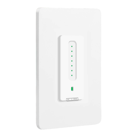
Martin Jerry STD01 User manual

User Manual for IOT devices
Part 1 - Installation (STD01)
Check Items before Installation
1. Power off the break
2. Light bulbs are dimmable (If not sure, send us the brand and model of it)
3. Make sure there is a neutral wire for the master switch. If not, the switches cannot work properly. It is in
white and NOT used by your old switch. You can send us photos of the wires for both 3-way switches.
Email: martinjerry01@outlook.com
Neutral

User Manual for IOT devices
Part 1 - Installation (STD01)
FQA:
1. How can I know it is connected correctly?
A: Press the on/off button, dim button on both Master and Add-On switch. They should work properly.
Indicator lights on the Master Switch can show the brightness of light bulbs.
2. After installing the Add-On switch, I see all indicator lights flash on the Mater Switch. What’s wrong?
A: This means the TRA-1 and TRA-2 are reversed. Just check and change them back.
3. I cannot find the neutral wire in both outlet boxes; Can I still use this 3-way dimmer switch?
A: No, the neutral wire is necessary for the Master Switch.
Although your old switches do not need a neutral wire. There are spare white neutral wires in the outlet
box. Please send us photos of the wires inside the outlet boxes.
4. How can I find which one is the live (hot) line, neutral wire?
A: Besides the ground wire, there are three wires on your old switch in general:
1 black & 1 red wire from the same location, they are TRA-1 & TRA-2;
1 black wire from another location, it is live or load. You can use a tester to test it.
If it is live (hot) wire, install Master Switch here;
If it is load wire, install Add-on Switch here.
https://www.youtube.com/watch?v=Xp4FWJRzHdo
5. How can I calibrate the dimming range and flicker problems?
A: Turn on the light bulb and use the Knob on the bottom of the switch to adjust and calibrate.
NO YES
Knob for calibration

User Manual for IOT devices
Part 1 - Installation (STD01)
Now Wire the two switches according to the diagram below:
Tips:
Wires on your old switches are:
1st Switch: Live, TRA1, TRA2
2nd Switch: Load, TRA1, TRA2
TRA-1 & TRA-2 is very easy to identify. Generally 1red, 1black. They come from the same location and
both connect to the old switch.
Neutral wires are not used by your old switch.
Recommended Connection procedures
1. Master Switch
1.1. Connect Ground Wire (Copper or Green. This is not necessary)
1.2. Connect Neutral Wire (White, not on old switch. This is necessary for wifi switch)
1.3. Connect Live Wire (Black, hot wire on old switch)
1.4. Turn on the breaker, and the indicator on the switch will light up. If not, send us a photo of the wiring
1.5. Turn of the breaker
1.6. Connect TRA-1 & TRA-2
2. Add-on Switch (Mater Switch must connect well first)
2.1. Connect TRA-1 with Red wires in the Wall
2.2. Connect TRA-2 and Load Wire with Black wire from the wall (3 of them together)
2.3. Turn on the breaker; both Master and Add-on Switch can manually turn on/off dim the light bulb.

User Manual for IOT devices
Part 2 - Download Smart LifeApp
Step 2: Register a New Account
Password must contain
6-20 letters and numbers
Register with phone number
or email address
4
5
3
6

Part 3 - Wi-Fi Connection
READ HERE!!!
1. Confirm that both the Master and Add-on Switch work well manually (ON/OFF, Dim). If not, go back to the
wiring part.
2. 2.4G WiFi is available. NOT support 5G (802.11av)
Step 1: Set the Switch to Easy Pairing Mode
1. Press the tiny restart button under the main power button to restart the switch. You will see the indicator is
in constant RED.
2. Press and hold the power button for 5-8s until the indicator blinks quickly in RED.
Power Button
Indicator
Restart Button

User Manual for IOT devices
Part 3 - Wi-Fi Connection
Step 2: Pair the switch on App
1. Confirm that you have downloaded the right Smart LifeApp (Same Logo as the right side)
If not, download it from the links
iPhone: https://itunes.apple.com/us/app/smart-life-smart-living/id1115101477?mt=8
Android: https://play.google.com/store/apps/details?id=com.tuya.smartlife&hl=en_US
1.”+”
2. All devices
3. Wall Switch
4

User Manual for IOT devices
Part 3 - Wi-Fi Connection
QA:
Q1: I follow all of the process above, but cannot get the switch connect to the WiFi (2.4G). Any
suggestions?
A: Please try our AP mode, which is more compatible. If the AP mode fails again, send your App account id to
How to Access AP mode?
1. Press the tiny restart button under the main power button to restart the switch. You will see the indicator is
in constant RED.
2. Press and hold the power button for 5-8s until the indicator blinks quickly in RED.
3. Press and hold the power button for 5-8s until the indicator blinks slowly in RED.
How to Pair in AP mode?
Follow the pairing process (Step 1 to Step 3) above, and choose AP Mode on the 4th step.
Then it will guide you to connect a hotspot like “SmartLife …”
4

User Manual for IOT devices
Part 4 - Alexa & Google Home
READ HERE!!!
3. It can be controlled by App well when your smart phone is under 3G/4G status (NOT Wi-Fi).
If not, check your Wi-Fi router connects to the Internet and pair the switch again.
Part 4.1: Connect the Smart Switch to Alexa
Step 1: Log in your Alexa account on a smartphone
or a computer, then tap Home Skills
Step 2: Search “Smart Life” and select the right one
according the blue logo (same with App)

User Manual for IOT devices
Part 4 - Alexa & Google Home
Step 3: Enable the skill
Step 4: Login the account you registered on the App in
Part 2, then click “Link Now”
Step 5: The Account is linked successfully, and then
tap Authorize to Complete.
Step 6: Congratulations! Alexa Devices (Echo) can
control the switch ON/OFF.
The account and password MUST the
same that you registered in the smart life
app (Email or Tel)
DO NOT input your Alexa account or use
another account

User Manual for IOT devices
Part 4 - Alexa & Google Home
http://www.martinjerry.com/std01support
If you want to delete or add new switches, please
delete or add them in the Smart Life App, the
Alexa will synchronize automatically.
If you cannot see the name of switches in the
Devices List in Alexa Page, you can click “Discover”
in Alexa Page, it will synchronize from the Smart
Life App.

User Manual for IOT devices
Part 4 - Alexa & Google Home
http://www.martinjerry.com/std01support
Part 4.2: Connect your Smart Switch to Google Home
Step 1: Find "Home Control" in the hamburger menu on the Google Home app’s home page -> Home Control ->
then tap "+".
Step 2: Find "Smart Life" in the list.
Step 3: Input your Smart Life account and password
you registered in Part 2, then tap "Link Now".
The account and password MUST the
same that you registered in the smart life
app (Email or Tel)
DO NOT input your Google account or use
another account

User Manual for IOT devices
Part 4 - Alexa & Google Home
http://www.martinjerry.com/std01support
Step 4: After you assign rooms for devices, your devices will be listed in the Home Control page.
Step 5: Control your smart devices through Google Home
Now you can control your smart devices through Google Home. If you set the switch name as “bedroom light”,
the supported voice commands are as below:
Ok Google, turn on bedroom light.
Ok Google, turn off bedroom light.

User Manual for IOT devices
FCC Compliance Notice
http://www.martinjerry.com/std01support
FCC Compliance Notice
This device complies with Part 15 of the FCC Rules. Operation is subject to the following two conditions: (1) This
device may not cause harmful interference, and (2) This device must accept any interference received, including
interference that may cause undesired operation.
Any changes or modifications not expressly approved by the party responsible for compliance could void the
user’s authority to operate the equipment.
This equipment complies with FCC radiation exposure limits set forth for an uncontrolled environment. This
equipment should be installed and operated with minimum distance 20cm between the radiator& your body.
This transmitter must not be co-located or operating in conjunction with any other antenna or transmitter.
This equipment has been tested and found to comply with the limits for a Class B digital device, pursuant to part
15 of the FCC Rules. These limits are designed to provide reasonable protection against harmful interference in a
residential installation. This equipment generates, uses and can radiate radio frequency energy and, if not installed
and used in accordance with the instructions, may cause harmful interference to radio communications. However,
there is no guarantee that interference will not occur in a particular installation. If this equipment does cause
harmful interference to radio or television reception, which can be determined by turning the equipment off and
on, the user is encouraged to try to correct the interference by one or more of the following measures:
—Reorient or relocate the receiving antenna.
—Increase the separation between the equipment and receiver.
—Connect the equipment into an outlet on a circuit different from that to which the receiver is connected.
—Consult the dealer or an experienced radio/TV technician for help.
Table of contents
Other Martin Jerry Switch manuals