Martin Professional Inground 200 User manual

martinarchitectural
Installation
Guide
Inground 200

© 2004 Martin Professional A/S, Denmark.
All rights reserved. No part of this guide may be reproduced, in any form or by any means, with-
out permission in writing from Martin Professional A/S, Denmark.
Printed in Denmark.
P/N 35000151, Rev B
340
310
7
496
Dimensions
Measurements are in millimeters

Contents
1. Introduction . . . . . . . . . . . . . . . . . . . . . . . . . . . . . . . . . . . . . . . . . . . . . . . . .5
Included items . . . . . . . . . . . . . . . . . . . . . . . . . . . . . . . . . . . . . . . . . . . . . . 5
2. Safety precautions . . . . . . . . . . . . . . . . . . . . . . . . . . . . . . . . . . . . . . . . . . .5
Eliminating fire risk . . . . . . . . . . . . . . . . . . . . . . . . . . . . . . . . . . . . . . . . . . . 5
Protecting the public . . . . . . . . . . . . . . . . . . . . . . . . . . . . . . . . . . . . . . . . . .6
3. Installation procedure . . . . . . . . . . . . . . . . . . . . . . . . . . . . . . . . . . . . . . . .6
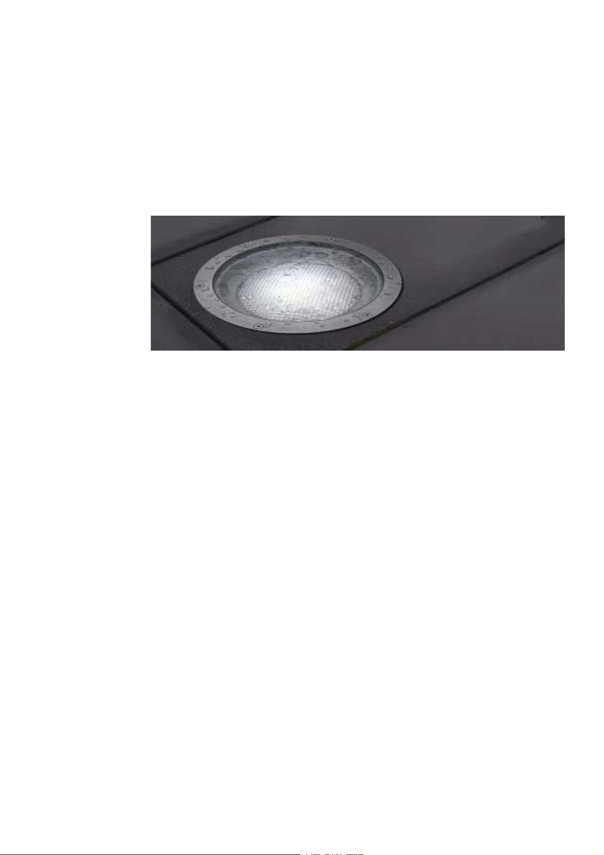
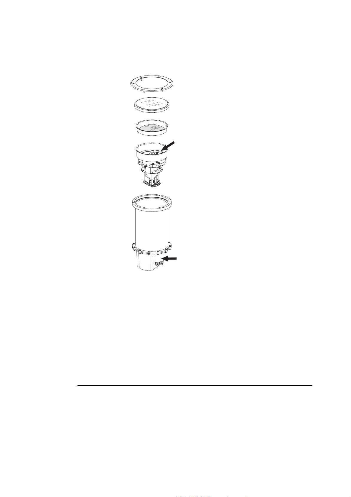
4. Exploded view . . . . . . . . . . . . . . . . . . . . . . . . . . . . . . . . . . . . . . . . . . . . . . .7
5. Groundwork . . . . . . . . . . . . . . . . . . . . . . . . . . . . . . . . . . . . . . . . . . . . . . . . .7
Choosing a location . . . . . . . . . . . . . . . . . . . . . . . . . . . . . . . . . . . . . . . . . .7
Safety . . . . . . . . . . . . . . . . . . . . . . . . . . . . . . . . . . . . . . . . . . . . . . . . . . 7
Stability and weight-bearing capacity . . . . . . . . . . . . . . . . . . . . . . . . . . 8
Water resistance and drainage . . . . . . . . . . . . . . . . . . . . . . . . . . . . . . .8
Disturbance by roots . . . . . . . . . . . . . . . . . . . . . . . . . . . . . . . . . . . . . . .8
Service access . . . . . . . . . . . . . . . . . . . . . . . . . . . . . . . . . . . . . . . . . . .8
Installation options . . . . . . . . . . . . . . . . . . . . . . . . . . . . . . . . . . . . . . . . . . . 9
1. Installation sleeve . . . . . . . . . . . . . . . . . . . . . . . . . . . . . . . . . . . . . . . 9
Sleeve installation: example. . . . . . . . . . . . . . . . . . . . . . . . . . . . . .9
Temporary installation sleeve cover. . . . . . . . . . . . . . . . . . . . . . . . 9
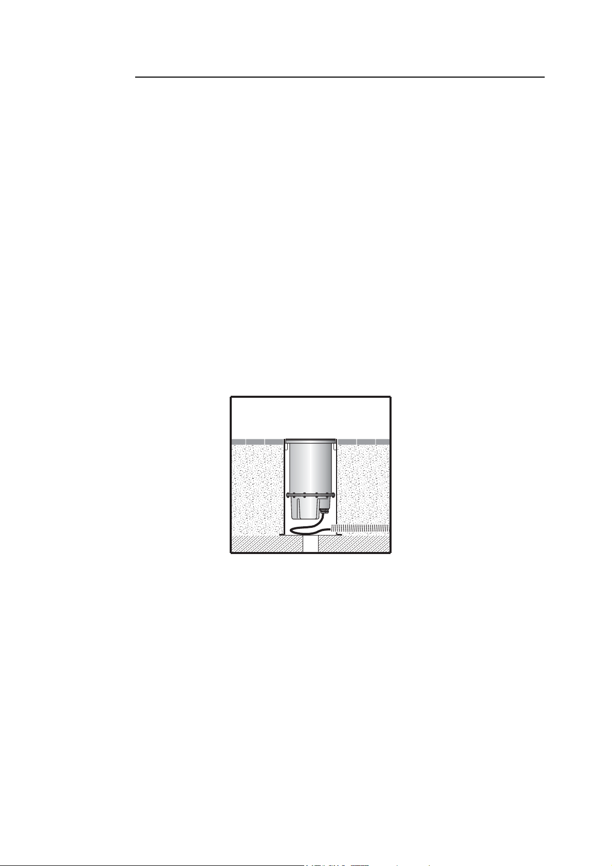
2. Direct burial . . . . . . . . . . . . . . . . . . . . . . . . . . . . . . . . . . . . . . . . . . . .9
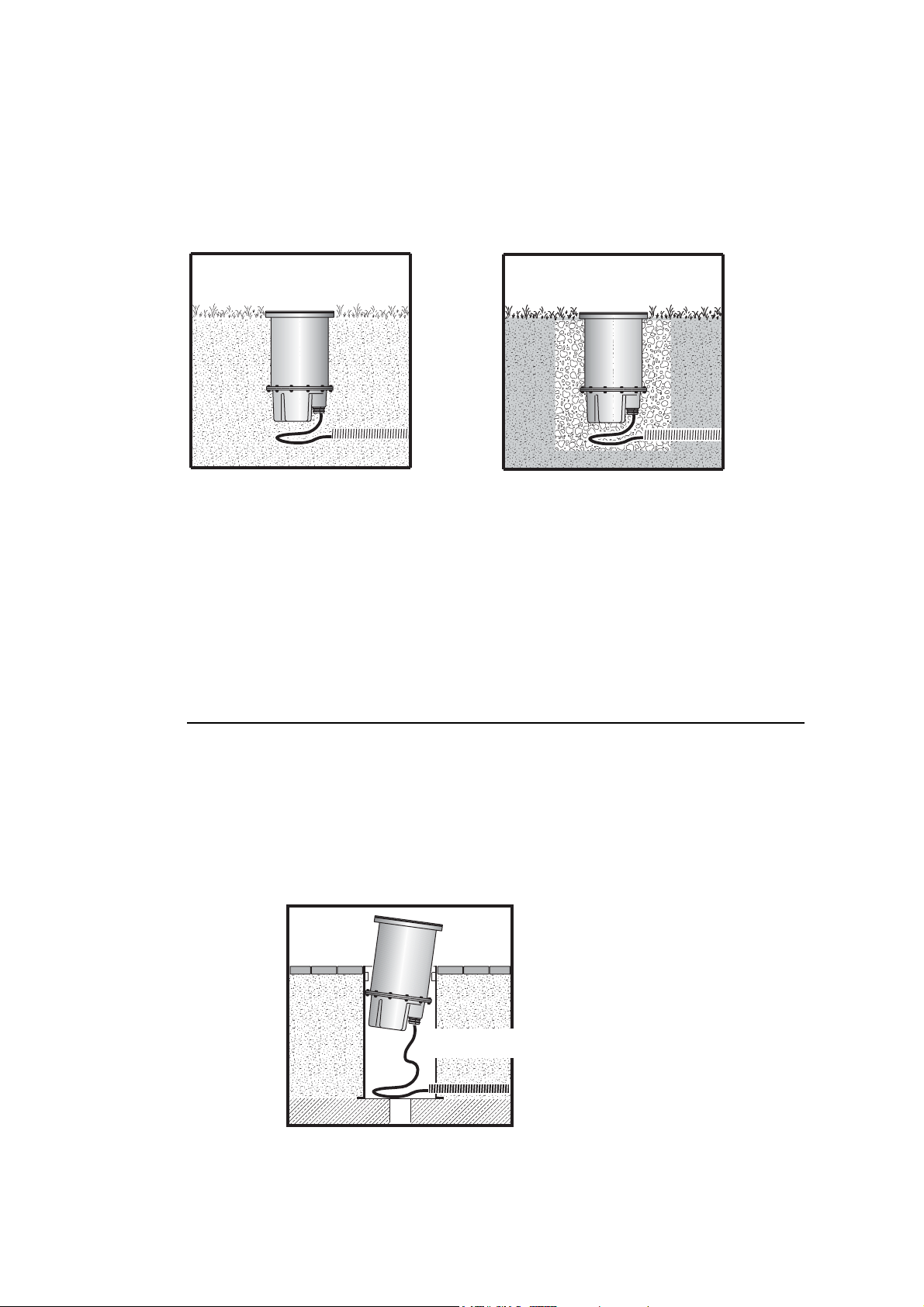
Direct burial: examples. . . . . . . . . . . . . . . . . . . . . . . . . . . . . . . . . 10
Cable installation . . . . . . . . . . . . . . . . . . . . . . . . . . . . . . . . . . . . . . . . . . .10
Cable slack . . . . . . . . . . . . . . . . . . . . . . . . . . . . . . . . . . . . . . . . . . . . . 10
6. Power and data connection . . . . . . . . . . . . . . . . . . . . . . . . . . . . . . . . . . 11
AC power supply . . . . . . . . . . . . . . . . . . . . . . . . . . . . . . . . . . . . . . . . . . .11
Power supply settings . . . . . . . . . . . . . . . . . . . . . . . . . . . . . . . . . . . . .11
Cable glands . . . . . . . . . . . . . . . . . . . . . . . . . . . . . . . . . . . . . . . . . . . . 11
Connecting power supply cables . . . . . . . . . . . . . . . . . . . . . . . . . . . . . . . 11
Control data cabling . . . . . . . . . . . . . . . . . . . . . . . . . . . . . . . . . . . . . . . . . 13
Planning cable layout . . . . . . . . . . . . . . . . . . . . . . . . . . . . . . . . . . . . . 13
Connecting control data cables . . . . . . . . . . . . . . . . . . . . . . . . . . . . . . . . 14
7. Powering on for the first time . . . . . . . . . . . . . . . . . . . . . . . . . . . . . . . .15
6 Color model test program. . . . . . . . . . . . . . . . . . . . . . . . . . . . . . . . . 15
Full Spectrum CMY model test program . . . . . . . . . . . . . . . . . . . . . . .15
8. Set-up and adjustment. . . . . . . . . . . . . . . . . . . . . . . . . . . . . . . . . . . . . . .16
Beam adjustment . . . . . . . . . . . . . . . . . . . . . . . . . . . . . . . . . . . . . . . . . . .16
Condensation and humidity . . . . . . . . . . . . . . . . . . . . . . . . . . . . . . . . . . . 17
9. Component removal & reinstallation . . . . . . . . . . . . . . . . . . . . . . . . . . 17
Front glass and lens: removal and refitting . . . . . . . . . . . . . . . . . . . . . . .17
Refitting the lens and front glass . . . . . . . . . . . . . . . . . . . . . . . . . . . . .17
Lamp module: removal and refitting . . . . . . . . . . . . . . . . . . . . . . . . . . . . .18
10. Installation specifications. . . . . . . . . . . . . . . . . . . . . . . . . . . . . . . . . . . 19


Introduction 5
1. Introduction
Thank you for selecting the Martin Inground 200, a 150 watt uplight designed for exterior burial
installation.
This Installation Guide describes how to:
• prepare groundwork (installation well, etc.) before installation
• connect cables
• adjust the beam angle and have the Inground 200 ready for operation
For details of operating the Inground 200, please refer to the User Manual shipped with the product.
The most recent versions of the User Manual and this Installation Guide are also available in the
Support area of the Martin Architectural website at http://www.martin-architectural.com
Included items
The Inground 200 is supplied with the following items:
• Philips CDM-SA/T 150W/942 lamp
• 4 blanking plugs for cable entry holes
• 2 stainless steel IP68 cable glands for AC power cable entry
(M25 x 1.5; designed for cable Ø13-17mm / Ø 0.51-0.67 in.)
• Installation guide
• User manual
Inground 200 6 Color and Full Spectrum CMY models are also supplied with the following items:
• 2 stainless steel IP68 cable glands for control cable entry
(M16 x 1.5; designed for cable Ø 5-9mm / Ø 0.2-0.35 in.)
2. Safety precautions
Warning! This product is not for household use. Installation of the Inground 200 may only be
carried out by qualified professionals.
This product presents risks of lethal or severe injury due to fire and heat, electric shock and lamp
explosion.
Read this guide before installing the fixture. Follow all safety precautions listed in this guide.
Observe all warnings in this guide and on the fixture.
Before attempting to operate the Inground 200, refer to the User Manual supplied with the product.
The User Manual is also available in the Support area of the Martin Architectural website at
http://www.martin-architectural.com
If you have questions about how to install the fixture safely, please contact your Martin Architectural
dealer or call the Martin 24-hour service hotline on +45 70 200 201.
Eliminating fire risk
The Inground 200 must be installed:
• Outdoors or in a well-ventilated area.

6 Installation procedure
• At least 0.5 meters (20 inches) away from the surface to be illuminated.
• At least 1 meter away from any combustible materials.
Ensure that:
• Litter, dry leaves or other combustible materials cannot accumulate on or near the fixture.
• Vehicles or other fire risks cannot be left unattended over or near the fixture. This is particularly
important in situations where a vehicle may be left unattended over or near an unlit fixture which is
later switched on.
Protecting the public
To avoid injury to members of the public, install the Inground 200:
• In an area where accidental contact with the front glass is unlikely, since the Inground 200
becomes hot during normal operation.
• Flush with the surrounding surface, so as to eliminate any obstacle to pedestrians that might result
in falls or injuries.
Ensure all local safety regulations and legal requirements are observed, and take appropriate
measures to warn or restrict access. To avoid accidents during installation or service, restrict access
to the site and place both warning notices and barriers around all work areas until work is completed
and all covers, etc. are correctly in place.
3. Installation procedure
A suggested procedure for installing the Inground 200 involves two phases:
1. Pre-installation
1. Ensure that a plan is available with details of site layout, beam aiming, power
supply and control, etc.
2. Prepare installation wells and cabling.
– see “Groundwork” on page 7
3. If an installation sleeve is to be used, fit and secure this.
– see “1. Installation sleeve” on page 9
2. Installation
1. Remove internal components and prepare for cable connection.
– see “Component removal & reinstallation” on page 17
2. Connect cables.
– see “Connecting power supply cables” on page 11 and “Connecting control
data cables” on page 14.
3. Replace internal components and install housing in installation well or sleeve.
– see “Component removal & reinstallation” on page 17
4. Apply power.
– see “Powering on for the first time” on page 15
5. Adjust beam and refit lens and front glass.
– see “Beam adjustment” on page 16

Exploded view 7
4. Exploded view
5. Groundwork
This section describes how to install the Inground 200 either directly in the ground or in an
installation sleeve.
Warning! All electrical system installation must be performed by qualified professionals.
It is the installer’s responsibility to ensure that all national safety regulations and
legal requirements are followed when installing the Inground 200.
Choosing a location
Safety
The Inground 200 must be installed in a location that meets the safety standards listed under “Safety
precautions” on page 5. It is the installer’s responsibility to ensure that all local safety regulations
and legal requirements are observed.
Trim ring
Front glass with seal
Lens
Lamp module
Connections compartment
Beam adjustment ring
Housing

8 Groundwork
Stability and weight-bearing capacity
If the Inground 200 is to be installed in a location where pedestrians or vehicles are likely to put
weight on the fixture, use a drive-over installation sleeve (see “1. Installation sleeve” on page 9).
Water resistance and drainage
The Inground 200 has an ingress protection rating of IP 65/67. This means that the fixture is
protected against low-pressure water jets and immersion. However, the product is not designed to
withstand high-pressure water jets.
As a sensible precaution, make sure that it is possible for water to leave the installation well or
sleeve at least as fast as it can enter it. An installation should be capable of draining away water
from the heaviest rain or snowfall in the area where the Inground 200 is located.
To minimize the risk of flooding or waterlogging, install the fixture in a location which is above the
level of the surrounding area, and make sure drainage conditions are adequate.
Disturbance by roots
The further the fixture is located from vegetation such as trees, hedges or bushes, the less chance
there is that the growth of roots will disturb the fixture or even cause damage to the fixture and its
cables. If the fixture is to be located close to vegetation, consult a landscape architect about the
possibility of disturbance by root systems.
Service access
Access to the outside of the Inground 200 housing is only necessary during cable installation or
cable replacement. All internal components and cable connections can be accessed for service
through the top of the fixture without having to remove the housing from its installation site.

Groundwork 9
Installation options
There are two methods of installing the Inground 200:
1. Installation sleeve
2. Direct burial
1. Installation sleeve
Use of an installation sleeve is recommended for hardscape locations (tarmac, stone paving, etc.)
and in landscape locations where the Inground 200 groundwork may be subjected to loads from
pedestrians or vehicles (including grasscutting or gardening equipment, motorcycles, emergency
services, etc.). Use of an installation sleeve will also allow work to be carried out in two stages:
1. Pre-installation (excavation, conduit-laying and groundwork preparation). This can be carried out
by construction personnel.
2. Installation (cable pulling and connection, fixture installation and adjustment). This must be
carried out by qualified electrical personnel only.
A steel installation sleeve for the Inground 200 is available (contact your Martin Architectural dealer
or see the Martin Architectural website at http://www.martin-architectural.com for full details). The
Inground 200 in a correctly installed drive-over installation sleeve will support a weight of 5000kg
from a vehicle tire.
Sleeve installation: example
The example installation below shows how adequate support and drainage can be achieved, but the
installer must make allowance for local conditions:
Temporary installation sleeve cover
To avoid rainwater and dirt gathering in empty installation sleeves while waiting for the Inground 200
to be installed in them, a temporary cover is supplied with each sleeve.
Important! The temporary installation sleeve cover is not designed to support weight, so ensure
that pedestrians and vehicles are kept away from the sleeve by using warning
notices and barriers.
2. Direct burial
Burying the Inground 200 directly in sand, gravel or shale, etc. is suitable in landscape installations
only. While the fixture itself will bear up to 5000kg (11,023lb), groundwork in direct burial
installations is unlikely to remain stable if loads are applied to the fixture. Therefore, in all hardscape

10 Groundwork
locations and in landscape locations where loads may be placed on the fixture by for example
vehicles or pedestrian traffic, an installation sleeve is required (see “1. Installation sleeve” on page
9).
Direct burial: examples
The example installations below show how an Inground 200 can be buried directly, but the installer
must make allowance for local conditions:
It is vital to ensure that the base of the housing rests firmly on a strong foundation, so that any
pressure on the top surface of the fixture after installation will not press the fixture into the ground.
One possible way of achieving this is to pack crushed stone or hardcore firmly in the bottom of the
installation well to support the housing.
Ensure that cables are not stressed or crushed during installation, and ensure that the housing rests
on its base, and not on the cables.
Tip! When creating a strong foundation for the Inground 200, remember to allow for
drainage.
Cable installation
Important! The installer must make sure that all national safety regulations and legal
requirements are followed when selecting and installing cables, conduit, warning
tape, controllers and all related items for the Inground 200.
Cable slack
Allow at least 80cm (2ft 8in) of free cable in the installation well or sleeve so that the fixture can be
lifted clear for service without disconnecting cables.
Minimum 80cm cable slack

Power and data connection 11
6. Power and data connection
This section describes how to connect the Inground 200 to AC power. For Inground 200 6 Color and
Full Spectrum CMY models, it also describes how to connect control data cables.
AC power supply
Warning! For protection from potentially lethal electric shock:
• The fixture must be grounded (earthed).
• The AC mains supply must be fitted with a fuse or circuit breaker, ground-fault
protection, and a means to isolate the fixture from the mains during service or
when not in use.
• Cables and fixtures must be isolated from AC power, and steps taken to prevent
reconnection, before carrying out any work on them.
• Voltage and frequency settings must be checked before applying power.
• The fixture must not be connected to an electrical dimmer system: doing so can
damage the electronics.
Power supply settings
The Inground 200 is configured at the factory for one of the two power supply settings listed in Table
1 below. The factory power supply settings are printed on the product serial number labels outside
and inside the housing. If your local AC voltage or frequency differ from the settings for your model,
the fixture’s power supply must be rewired by an authorized Martin Architectural service dealer.
Cable glands
Cable glands must be replaced if the power or data cable is replaced with a cable of a different
diameter. Replacement glands, available from electrical suppliers, must have the following
characteristics.
Temperature range: ........................................................ -20° to 70° C or better
Ingress protection rating: ................................................................. IP 67 or 68
Power cable gland thread size: ......................................................... M25 x 1.5
Data cable gland thread size: .............................................................M16 x 1.5
Minimum entry thread length: .................................................................. 8mm
Connecting power supply cables
The Inground 200 is supplied with 2 stainless steel M25 x 1.5mm cable glands, water resistant to
IP68, for AC power cable entry. The glands accept from 13 to 17mm diameter cable.
Voltage Frequency
230 V 50 Hz
210 V 60 Hz
Table 1: Default Power Supply Settings

12 Power and data connection
To connect the AC power cables:
1. If the internal components are not already removed to give access to the cable connection
compartment, remove them (see “Component removal & reinstallation” on page 17).
2. Remove the three 5mm Allen screws from the cable compartment cover and carefully lift the
cover off, being careful not to damage the seal:
3. Working from outside the fixture, unscrew one of the two larger blanking plugs on the bottom of
the cable compartment. Dismantle a power cable gland and screw the cable entry into the hole
with its rubber O-ring facing inwards, so that the O-ring makes a seal against the housing.
Tighten sufficiently to make a water-resistant seal. Do not over-tighten, as this may damage the
seal.
4. Thread the power arrival cable through the compression nut, washer, rubber gland and cable
entry into the fixture. Remember to allow at least 80cm (2ft 8in) of cable slack in the installation
well or sleeve, so that the Inground 200 can be lifted clear for cable disconnection or service.
5. Prevent the cable entry from turning by holding it with a wrench. Tighten the compression nut
sufficiently to make a water-resistant seal. Do not over-tighten, as this may damage the seal.
6. If power cable is to continue to another fixture, repeat steps 3 to 5 for the power exit cable.
7. Working inside the fixture, connect the Inground 200’s green wire to ground (earth), its black wire
to live, and its white wire to neutral. If power cable is to continue to another fixture, connect power
in and power out cables to the same terminals on the fixture, so that the Inground 200 is
connected to AC power in parallel. Table 2 on page 13 shows some wire identification schemes;
consult an electrician if you have any doubts about proper installation.
8. If data cable also needs to be connected, move on to the next section in this guide. If data cable
does not need to be connected, examine the seal. If it shows any signs of damage or
deterioration, the PCB/power compartment cover must also be removed and the seal must be
replaced with a new one (available from Martin Architectural dealers: p/n 20600450).
5mm
Black: to DMX -
Brown: to DMX +
Shield: to DMX shield
Black: to AC live
White: to AC neutral
Green: to AC ground (earth)
AC power DMX control data

Power and data connection 13
9. If the seal is in good condition, place the connections compartment cover back into position,
being careful not to damage the seal, and tighten the three cover plate Allen screws by hand until
they are finger tight. Then use an Allen key to tighten each screw a further 3/4 turn only. The
cover will now be tight enough to achieve a waterproof seal.
Note: Do not overtighten, or you may damage the seal and invalidate the product warranty.
Do not apply silicone or any other kind of sealant. Doing so will also invalidate the product
warranty.
10. Replace the lamp module, lens and front glass (see “Component removal & reinstallation” on
page 17).
Control data cabling
Inground 200 6 Color and Full Spectrum CMY models require a data link for DMX controller
operation and for synchronized stand-alone operation of multiple fixtures.
Use only RS-485 data cable designed for burial for this purpose. RS-485 cable has low capacitance
and a characteristic impedance of 85 to 150 ohms. It is electrically shielded and has at least 1
twisted-pair of conductors. The minimum wire size is 0.2 mm2(24 AWG) for runs up to 300 meters
(1000 ft.) and 0.322 mm2(26 AWG) for runs up 500 meters (1640 ft).
A male 3-pin XLR connector should be fitted at the controller end of the data link to allow a standard
connection to Martin DMX controller and uploader devices. The XLR connector should be wired as
follows:
• Pin 1: shield
• Pin 2: DMX -
• Pin 3: DMX +
Note: to avoid ground/earth loop interference, make sure the DMX cable shield does not come into
contact with the shell or body of the XLR connector.
Planning cable layout
The following considerations must be taken into account when planning the layout of DMX control
cables:
• Fixtures must be ‘daisy-chained’, i.e. DMX must be connected in one single chain of fixtures.
Wire (EU) Wire (US) Function Marking Screw (US)
brown black live “L” yellow or
brass
blue white neutral “N” silver
yellow/green green ground green
Table 2: Mains Connections

14 Power and data connection
• The maximum permitted control data cable length is 500 meters (1640 ft). If more than 500 meters
of control data cable will be necessary, contact your Martin Architectural dealer for advice.
• Avoid long parallel runs of AC power and control data cables. Even if not required by law, separate
conduits are recommended for power and data cables.
• The last fixture in the chain must be terminated with a 120 Ohm resistor connected in parallel with
the fixture between the + (brown wire) and - (black wire) DMX terminals. Note that this only applies
to the last fixture in the chain. No resistor should be used on the other fixtures.
Connecting control data cables
Inground 200 6 Color and Full Spectrum CMY models are supplied with 2 stainless steel M16 x
1.5mm cable glands water resistant to IP68 for data cable entry. The glands accept from 5 to 9mm
diameter cable.
To connect data cable:
1. If the internal components are not already removed to give access to the cable connection
compartment, remove them (see “Component removal & reinstallation” on page 17).
2. If the connection compartment cover has not already been removed, remove it for access (see
“Connecting power supply cables” on page 11)
3. Working from outside the fixture, unscrew a smaller blanking plug. Dismantle a data cable gland
and screw the cable entry into the hole in the bottom of the fixture housing with its rubber O-ring
facing inwards, so that the O-ring makes a seal against the housing. Tighten sufficiently to make
a water-resistant seal. Do not over-tighten, as this may damage the seal.
4. Thread data cable through the compression nut, washer, rubber gland and cable entry into the
fixture. Remember to allow at least 80 cm (2 ft 8 in) of cable slack in the installation well or
sleeve, so that the Inground 200 can be lifted clear for cable disconnection or service.
5. Prevent the cable entry from turning by holding it with a wrench. Tighten the compression nut
sufficiently to make a water-resistant seal. Do not over-tighten, as this may damage the seal.
6. If the data link is to be continued to another fixture, repeat steps 3 to 5 for the data out cable.
7. Working inside the fixture, connect the incoming DMX data cable to the Inground 200 data cable
tail. Connect DMX + to the Inground 200´s brown DMX wire, connect DMX - to the Inground
200´s black wire, and connect shield to shield. If the data link is to be continued to another fixture,
Black to DMX - and 120 Ohm resistor
Brown to DMX + and 120 Ohm resistor

Powering on for the first time 15
connect DMX output cable on the same terminals as the input cable, so that the fixture is
connected to DMX in parallel.
8. Refit the connections compartment cover, being careful not to damage the seal. If the seal shows
any signs of damage or deterioration, the PCB/power compartment cover must also be removed
and the seal must be replaced with a new one (available from Martin Architectural dealers: p/n
20600450).
9. Refit the lamp module, lens and front glass (see “Component removal & reinstallation” on page
17).
7. Powering on for the first time
After all connections and cables are installed, and after the site has been made safe, the Inground
200 can be powered on for testing and beam adjustment.
When fixtures are powered on, lamps strike after a short delay. When programmable Inground 200
models are powered on for the first time, they will run through a factory-set light show for test
purposes. They will continue to run this test sequence until they are programmed.
6 Color model test program
The 6 Color fixture is pre-programmed with 7 scenes, to verify that all colors and the dimmer are
working correctly.
1. White 100% intensity.
2. Color 1 100% intensity.
3. Color 2 100% intensity.
4. Color 3 100% intensity.
5. Color 4 100% intensity.
6. Color 5 100% intensity.
7. White 0% intensity (no light).
Full Spectrum CMY model test program
The Full Spectrum CMY fixture is pre-programmed with 5 scenes, to verify that all color-flags and
the dimmer are working correctly.
1. White 100% intensity.
2. Cyan 100% intensity.
3. Magenta 100% intensity.
4. Yellow 100% intensity.
5. White 0% intensity (no light).
Black: to DMX -
Brown: to DMX +
Shield: to DMX shield
White: to AC neutral
Green: to AC earth/ground
AC power DMX control data
Black: to AC live

16 Set-up and adjustment
8. Set-up and adjustment
Beam adjustment
Correct adjustment of the beam of the Inground 200 is critical for correct illumination of the target.
Adjustment is best carried out after dark.
Warning! Danger of burns, electric shock and lamp explosion!
• Beam adjustment must be carried out by authorized electrical personnel and in
clean, dry conditions only.
• Heat-resistant safety gloves and safety glasses must be worn.
• Do not look directly into the lamp.
• Make sure that nothing falls into the fixture while the front glass and lens are
removed.
You will need 4mm and 2.5mm Allen keys for this task.
To adjust the beam:
1. Depending on whether the Inground 200 has been in operation or not, ensure that the fixture is at
optimum temperature for adjustment by following one of these two alternatives:
a) If the fixture has been in operation before you want to adjust the beam, do not switch it off.
Instead, remove the front glass and lens (see “Front glass and lens: removal and refitting” on
page 17) and wait 15 minutes for the lamp module to cool slightly.
b) If the fixture has not been in operation before you want to adjust the beam, remove the front
glass and lens (see “Front glass and lens: removal and refitting” on page 17), apply power and
wait 15 minutes for the lamp to warm up to operating temperature.
2. Loosen the two 2.5mm beam adjustment ring Allen screws (A) and rotate the lamp module until it
can be tilted towards the target.
3. Make sure the beam adjustment ring screws (A) are pushed out towards the edges of the module
to engage the retaining clips, and retighten the screws to clamp the beam adjustment ring in
place.
A
A
B
A
2.5mm

Component removal & reinstallation 17
4. Loosen the tilt adjustment Allen screw (B) on the side of the beam adjustment ring. Adjust the tilt
angle from 0 - 15° by pushing down gently on the side of the lamp module top plate. Retighten
the tilt adjustment screw (B). Replace the lens.
5. Check that the target is illuminated as intended. If not, repeat step 4. When the desired
illumination is obtained, the tilt angle can be read from the guide next to the tilt adjustment screw
and noted for future reference.
6. Replace the front glass with its seal and trim ring, gradually cross-tightening the trim ring screws
to a maximum torque of 1.8 Nm/1.3 ft-lbs (see “Front glass and lens: removal and refitting” on
page 17).
Condensation and humidity
The Inground 200 is fitted with a self-purging valve that eliminates humidity problems. Any initial
condensation after installation will gradually disappear in normal use.
9. Component removal & reinstallation
Tasks such as beam adjustment, lamp replacement and cable connection require the removal and
reinstallation of certain components. This section contains instructions for these procedures.
Front glass and lens: removal and refitting
A 4mm Allen key is required for this operation.
1. Isolate the Inground 200 from AC power and allow to cool for at least 15 minutes.
2. Brush sand, dirt, etc. away and clean the Inground 200 and surrounding area to ensure that dirt
does not fall into the fixture.
3. Remove the six countersunk 4mm Allen screws and lift the trim ring off the fixture
4. Taking care to avoid damaging the seal, lift off the front glass and its seal.
5. Lift the lens out of the housing.
Refitting the lens and front glass
Important! Any damaged seals or screws must be replaced with new items. Two spare 4mm
countersunk Allen screws for the trim ring are supplied with the fixture.
The front glass seal, its seating surface in the housing, the front glass and the trim
ring must all be perfectly clean and dry to maintain a waterproof seal.
Warning! Do not use silicone or any other kind of sealant on the front glass seal, front glass,
housing or trim ring. Doing so will invalidate the product warranty.
4mm

18 Component removal & reinstallation
1. Inspect the front glass seal for damage before refitting. Replacement front glasses and seals are
available from Martin Architectural dealers (front glass: p/n 41700007, front glass seal: p/n
20600441).
2. Inspect the six countersunk Allen screws from the trim ring before reuse. Threads must be clean
and undamaged. Two spare screws are supplied with the fixture. Replacement screws are
available from Martin Architectural dealers (p/n: 08111314)
3. Refit the lens by lowering it into the housing, making sure that the screw in the seating engages
in the notch in the lens flange.
4. Place the front glass complete with its seal in the top of the housing and place the trim ring over
the front glass.
5. To make future service easier, apply a small amount of copper-based or silicone grease to the
threads of the trim ring screws before insertion.
6. See illustration below. Gradually cross-tighten the trim ring screws in the sequence illustrated to
1.8 Nm/1.3 ft-lbs.
Important! Cross-tighten gradually. Do not exceed the maximum torque of 1.8 Nm/1.3 ft-lbs., or
you may distort the trim ring and damage the seal. This will impair the Inground
200’s waterproof properties and invalidate the product warranty.
Lamp module: removal and refitting
This section describes removal and refitting of the lamp module to gain access to the connections
and PCB/power compartments at the bottom of the fixture. If you need to replace the lamp, please
refer to the Inground 200 User Manual.
To remove the lamp module:
1. Isolate the Inground 200 from AC power and allow to cool for at least 15 minutes.
2. Remove the front glass with seal and lens (see “Front glass and lens: removal and refitting” on
page 17).
3. Do not loosen the beam adjustment screws and avoid disturbing the beam adjustment settings.
Holding the lamp module by the beam adjustment ring, gently lift the whole module upwards until
it is clear of the housing. Note the positions of the lamp module wiring connectors, then
disconnect them and lift the lamp module out of the housing.
To refit the lamp module:
1. Reconnect the lamp module wiring connectors.
2. Note the position of the screw in the lamp module seating in the housing. Lower the lamp module
into the housing, rotating it if necessary so that the notch in the top of the lamp module engages
with the screw. The lamp module is now correctly oriented.
3. If beam settings have been disturbed, readjust the beam (see “Beam adjustment” on page 16).
4. Refit the lens, front glass with its seal and trim ring, and cross-tighten the trim ring screws
gradually to 1.8 Nm/1.3 ft-lbs (see “Front glass and lens: removal and refitting” on page 17).
A
B
C
DE
F

Installation specifications 19
10.Installation specifications
Dimensions
Height .......................................................................................................................................496mm (19.53in.)
Trim ring outer Ø ......................................................................................................................340mm (13.39 in.)
Trim ring thickness .........................................................................................................................7mm (0.28 in.)
Top flange outer Ø .....................................................................................................................310mm (12.2 in.)
Weight-bearing capacity
Front glass (load from pneumatic tire) ..................................................................................... 5000kg (11,023lb)
Inground 200 in installation sleeve with suitable groundwork .................................................. 5000kg (11,023lb)
Cable entry
AC power entry .......................................................2 x threaded holes, M25 x 1.5, thread length 8mm (0.31 in.)
AC power cable glands ...............................2 x stainless steel (IP 68), M25 x 1.5, Ø 13-17mm (Ø 0.51-0.67 in.)
Control data cable entry ..........................................2 x threaded holes, M16 x 1.5, thread length 8mm (0.31 in.)
Control cable glands (6 Color and Full Spectrum CMY models)......2 x stainless steel (IP 68), M16 x 1.5,
Ø 5-9mm (Ø 0.2-0.35 in.)
Ordering information: accessories
Front glass ..................................................................................................................................... P/N 41700007
Front glass seal ............................................................................................................................ P/N 20600441
Connections compartment/power compartment seal ....................................................................P/N 20600450
Installation sleeve...........................................................................................................................P/N 91611194
For full product specifications and ordering information, please refer to the User Manual.

www.martin-architectural.com •Olof Palmes Allé 18 •8200 Aarhus N •Denmark
Tel: +45 8740 0000 •Fax +45 8740 0010
Table of contents
Popular Landscape Lighting manuals by other brands

AquaScape
AquaScape 84030 installation instructions

Volt
Volt Top Dog Scotty Mini Twinnovator Brass installation instructions

AMP Lighting
AMP Lighting HydraPro AWL-5006-B-BZ Installation & maintenance guide

Volt
Volt 310 Series installation instructions

AMP Lighting
AMP Lighting AlpinePro Path Light Installation & maintenance guide

Intermatic
Intermatic Malibu LZ312 quick start guide