Martin Professional Stagebar 54 User manual

Stagebar 54
user manual

Dimensions
230
190
105
420
230
190
105
630
Stagebar 54 S
Stagebar 54 S
Stagebar 54 L
Stagebar 54 L
All dimensions are in millimeters
©2007 Martin Professional A/S, Denmark. All rights reserved. No part of this manual may be reproduced, in any form or by any
means, without permission in writing from Martin Professional A/S. Information subject to change without notice. Martin Professional
A/S and all affiliated companies disclaim liability for any injury, damage, direct or indirect loss, consequential or economic loss or any
other loss occasioned by the use of, inability to use or reliance on the information contained in this manual. The use of certain patents
in Martin Stagebar products is licensed by Color Kinetics®, Inc. (see details printed on product).
P/N 35000195, Rev. C

Safety Information
The following symbols are used to identify important safety information on the product and in this manual:
Warning! Class 2M LED product. Do not look into the beam from a distance
of less than 40 cm (16 inches). Do not stare into the beam for extended
periods at a short distance. Do not view the beam directly with optical
instruments.
This product is for professional use only. It is not for household use.
This product presents risks of severe injury or death due to fire hazards, electric shock and falls.
Read this manual before installing, powering or servicing the fixture, follow the safety precautions listed
below and observe all warnings in this manual and printed on the fixture. If you have questions about how to
operate the fixture safely, please contact your Martin dealer or call the Martin 24-hour service hotline at +45
70 200 201.
PROTECTION FROM ELECTRIC SHOCK
• Shut down power to the entire installation at the building’s main power distribution board and lock out
power (by removing the fuse for example) before carrying out any installation or maintenance work.
• Disconnect the fixture from AC power before removing or installing any cover or part and when not in use.
• Always ground (earth) the fixture electrically.
• Use only a source of AC power that complies with local building and electrical codes and has both
overload and ground-fault (earth-fault) protection.
• Connect this fixture to AC power either using the supplied power cable or via 3-conductor cable that is
rated minimum 20 amp, hard usage. Suitable cable types include ST, SJT, STW, SEO, SEOW and STO.
• The voltage and frequency at the power outlet are the same as the voltage and frequency applied to the
power inlet. Only connect devices to the power outlet that accept this voltage and frequency.
• Before using the fixture, check that all power distribution equipment and cables are in perfect condition
and rated for the current requirements of all connected devices.
• Do not use the fixture if the power cable or power plug are in any way damaged, defective or wet, or if they
show signs of overheating.
WARNING!
Read the safety precautions in this section before
installing, powering, operating or servicing this
product.
DANGER!
Safety hazard.
Risk of severe
injury or death.
Warning!
LED light
emission. Risk
of eye injury.
Warning!
Refer to
manual before
installing,
powering or
servicing.
Warning!
Hazardous
voltage. Riskof
lethalorsevere
electric shock.
Warning!
Fire hazard.

• Do not expose the fixture to rain or moisture.
• Refer any service operation not described in this manual to a qualified technician.
PROTECTION FROM FIRE
• Do not attempt to bypass thermostatic switches or fuses. Replace defective fuses with ones of the
specified type and rating only.
• Provide a minimum clearance of 0.1 m (4 in.) around fans and air vents.
• Do not modify the fixture or install other than genuine Martin parts.
• Do not stick filters, masks or other materials directly onto LEDs.
• Do not operate the fixture if the ambient temperature (Ta) exceeds 40° C (104° F).
PROTECTION FROM INJURY
• Do not hang fixtures from each other. Use one clamp per fixture when suspending.
• When suspending the fixture, ensure that the structure and all hardware used can hold at least 10 times
the weight of all devices suspended from them.
• Use a secondary attachment (such as a safety cable) to secure each fixture. Secondary attachments
must be able to hold at least 10 times the weight of all devices suspended from them and must be
installed as described in this manual.
• Check that all external covers and rigging hardware are securely fastened.
• Block access below the work area and work from a stable platform whenever installing, servicing or
moving the fixture.
• The LED emission presents a hazard to eyesight at a distance of 4 - 40 cm (1.6 - 16 inches) when the eye
is exposed to the beam for longer than 0.25 seconds.
• Do not look at LEDs from a distance of less than 40 cm (1 ft. 4 in.) without suitable protective eyewear.
• Do not look at LEDs with magnifiers or similar optical instruments that may concentrate the light output.
Disposing of this product
Martin® products are supplied in compliance with Directive 2002/96/EC of the European
Parliament and of the Council of the European Union on WEEE (Waste Electrical and Electronic
Equipment), as amended by Directive 2003/108/EC, where applicable.
Help preserve the environment! Ensure that this product is recycled at the end of its life. Your
supplier can give details of local arrangements for the disposal of Martin products.

Contents
Dimensions . . . . . . . . . . . . . . . . . . . . . . . . . . . . . . . . . . . . . . . . . . . . . . . . . . . . . . . . . . . . . . . . . . . . . . . . 2
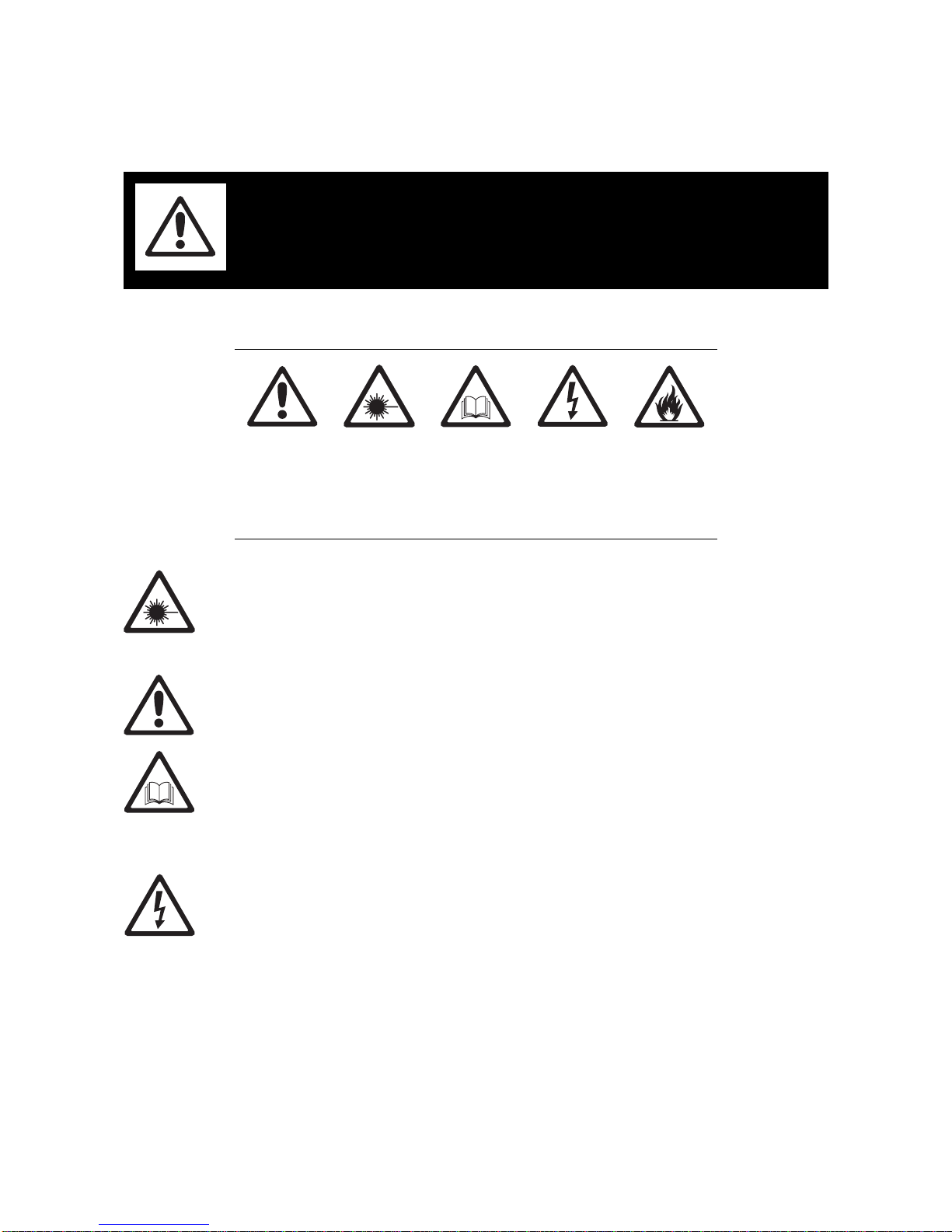
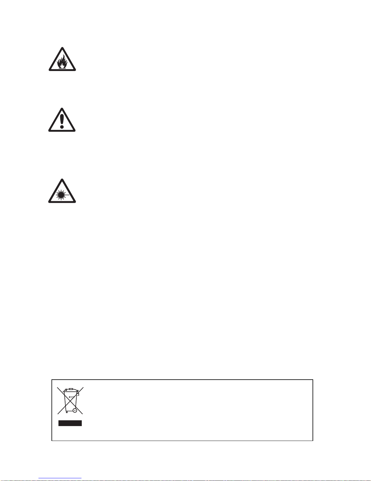
Safety Information. . . . . . . . . . . . . . . . . . . . . . . . . . . . . . . . . . . . . . . . . . . . . . . . . . . . . . . . . . . . . . . . . . 3
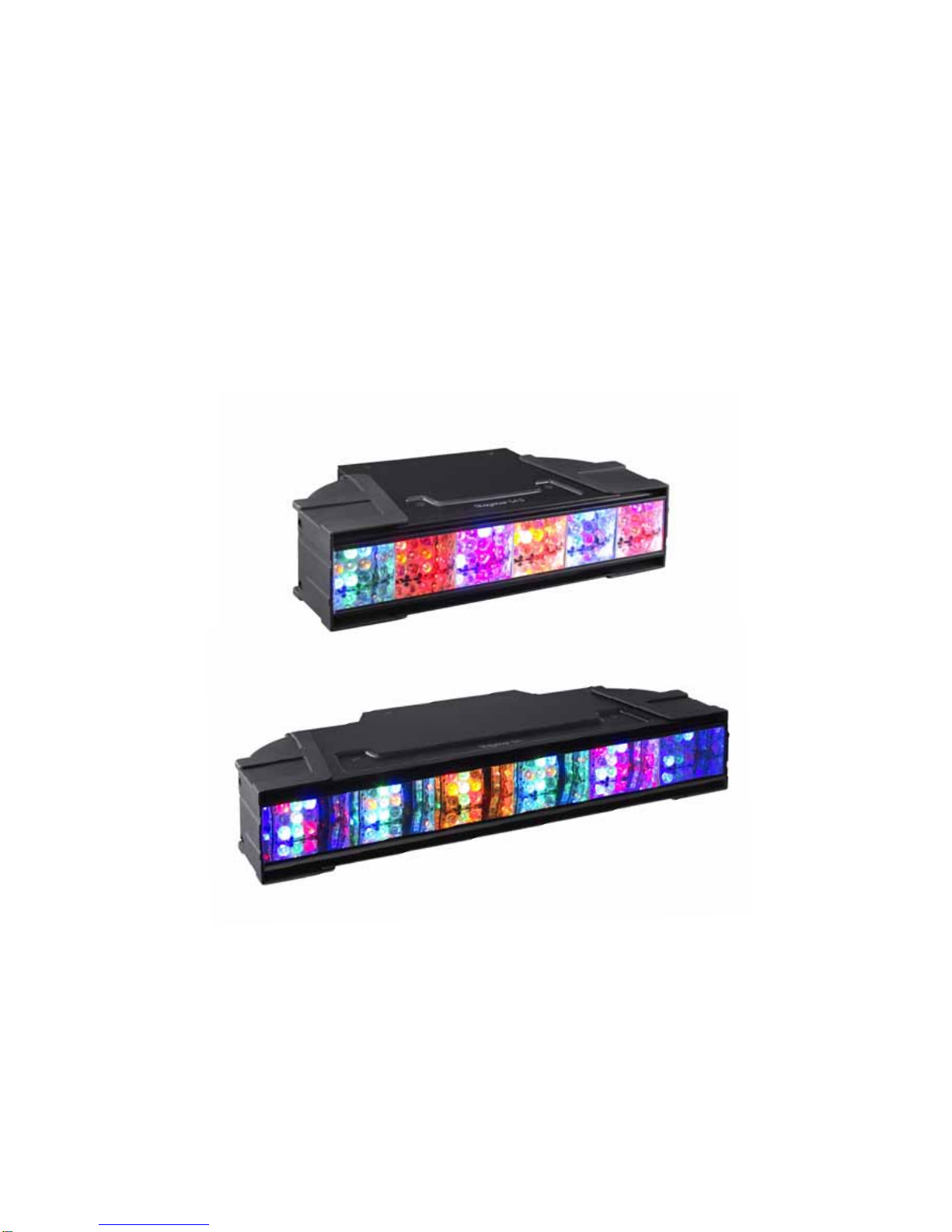
Product overview. . . . . . . . . . . . . . . . . . . . . . . . . . . . . . . . . . . . . . . . . . . . . . . . . . . . . . . . . . . . . . . . . . . 6
Introduction . . . . . . . . . . . . . . . . . . . . . . . . . . . . . . . . . . . . . . . . . . . . . . . . . . . . . . . . . . . . . . . . . . . . . . . . 7
Unpacking . . . . . . . . . . . . . . . . . . . . . . . . . . . . . . . . . . . . . . . . . . . . . . . . . . . . . . . . . . . . . . . . . . . . . . . . 7
Using for the first time . . . . . . . . . . . . . . . . . . . . . . . . . . . . . . . . . . . . . . . . . . . . . . . . . . . . . . . . . . . . . . . 7
Physical installation . . . . . . . . . . . . . . . . . . . . . . . . . . . . . . . . . . . . . . . . . . . . . . . . . . . . . . . . . . . . . . . . 8
Adjustable mounting bracket . . . . . . . . . . . . . . . . . . . . . . . . . . . . . . . . . . . . . . . . . . . . . . . . . . . . . . . . . . 8
Standing installation. . . . . . . . . . . . . . . . . . . . . . . . . . . . . . . . . . . . . . . . . . . . . . . . . . . . . . . . . . . . . . . . . 8
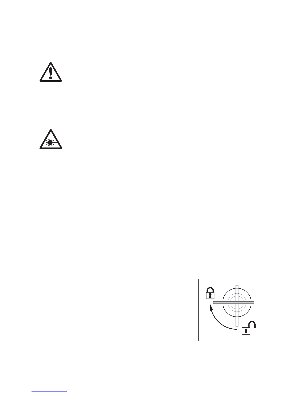
Flying from a truss, bar or other structure . . . . . . . . . . . . . . . . . . . . . . . . . . . . . . . . . . . . . . . . . . . . . . . . 8
AC power. . . . . . . . . . . . . . . . . . . . . . . . . . . . . . . . . . . . . . . . . . . . . . . . . . . . . . . . . . . . . . . . . . . . . . . . . . 9
Power connection . . . . . . . . . . . . . . . . . . . . . . . . . . . . . . . . . . . . . . . . . . . . . . . . . . . . . . . . . . . . . . . . . . 9
Relaying power to other devices . . . . . . . . . . . . . . . . . . . . . . . . . . . . . . . . . . . . . . . . . . . . . . . . . . . . . . . 9
Control data link. . . . . . . . . . . . . . . . . . . . . . . . . . . . . . . . . . . . . . . . . . . . . . . . . . . . . . . . . . . . . . . . . . . 11
Connection pinouts . . . . . . . . . . . . . . . . . . . . . . . . . . . . . . . . . . . . . . . . . . . . . . . . . . . . . . . . . . . . . . . . 11
Fixture setup. . . . . . . . . . . . . . . . . . . . . . . . . . . . . . . . . . . . . . . . . . . . . . . . . . . . . . . . . . . . . . . . . . . . . . 12
DMX addresses and DMX mode. . . . . . . . . . . . . . . . . . . . . . . . . . . . . . . . . . . . . . . . . . . . . . . . . . . . . . 12
Fixture settings . . . . . . . . . . . . . . . . . . . . . . . . . . . . . . . . . . . . . . . . . . . . . . . . . . . . . . . . . . . . . . . . . . . 13
Fixture readouts. . . . . . . . . . . . . . . . . . . . . . . . . . . . . . . . . . . . . . . . . . . . . . . . . . . . . . . . . . . . . . . . . . . 13
Other utilities . . . . . . . . . . . . . . . . . . . . . . . . . . . . . . . . . . . . . . . . . . . . . . . . . . . . . . . . . . . . . . . . . . . . . 13
Service and maintenance. . . . . . . . . . . . . . . . . . . . . . . . . . . . . . . . . . . . . . . . . . . . . . . . . . . . . . . . . . 14
Cleaning. . . . . . . . . . . . . . . . . . . . . . . . . . . . . . . . . . . . . . . . . . . . . . . . . . . . . . . . . . . . . . . . . . . . . . . . . 14
Removing and installing LED lenses . . . . . . . . . . . . . . . . . . . . . . . . . . . . . . . . . . . . . . . . . . . . . . . . . . . 15
Installing and removing the diffuser front. . . . . . . . . . . . . . . . . . . . . . . . . . . . . . . . . . . . . . . . . . . . . . . . 16
Fuse replacement . . . . . . . . . . . . . . . . . . . . . . . . . . . . . . . . . . . . . . . . . . . . . . . . . . . . . . . . . . . . . . . . . 16
Battery service. . . . . . . . . . . . . . . . . . . . . . . . . . . . . . . . . . . . . . . . . . . . . . . . . . . . . . . . . . . . . . . . . . . . 17
Reflector removal. . . . . . . . . . . . . . . . . . . . . . . . . . . . . . . . . . . . . . . . . . . . . . . . . . . . . . . . . . . . . . . . . . 17
Software installation. . . . . . . . . . . . . . . . . . . . . . . . . . . . . . . . . . . . . . . . . . . . . . . . . . . . . . . . . . . . . . . . 17
DMX protocols . . . . . . . . . . . . . . . . . . . . . . . . . . . . . . . . . . . . . . . . . . . . . . . . . . . . . . . . . . . . . . . . . . . . 18
RGB Mode. . . . . . . . . . . . . . . . . . . . . . . . . . . . . . . . . . . . . . . . . . . . . . . . . . . . . . . . . . . . . . . . . . . . . . . 18
RGBAW Mode. . . . . . . . . . . . . . . . . . . . . . . . . . . . . . . . . . . . . . . . . . . . . . . . . . . . . . . . . . . . . . . . . . . . 18
HSI Mode. . . . . . . . . . . . . . . . . . . . . . . . . . . . . . . . . . . . . . . . . . . . . . . . . . . . . . . . . . . . . . . . . . . . . . . . 18
HSIC Mode . . . . . . . . . . . . . . . . . . . . . . . . . . . . . . . . . . . . . . . . . . . . . . . . . . . . . . . . . . . . . . . . . . . . . . 19
Onboard control panel menus. . . . . . . . . . . . . . . . . . . . . . . . . . . . . . . . . . . . . . . . . . . . . . . . . . . . . . 20
Display messages. . . . . . . . . . . . . . . . . . . . . . . . . . . . . . . . . . . . . . . . . . . . . . . . . . . . . . . . . . . . . . . . . 21
Troubleshooting . . . . . . . . . . . . . . . . . . . . . . . . . . . . . . . . . . . . . . . . . . . . . . . . . . . . . . . . . . . . . . . . . . 22
Stagebar 54 specifications. . . . . . . . . . . . . . . . . . . . . . . . . . . . . . . . . . . . . . . . . . . . . . . . . . . . . . . . . 23

6 Stagebar 54 user manual
Product overview
A
B
EH
F
G
D
A
C
Stagebar 54 L
Stagebar 54 L
Stagebar 54 S
Stagebar 54 S
F
J
I
A - End cap release screws
B - Cooling fan
C - Data input connector (RJ-45)
Connect to DMX control data from the
controller or previous fixture.
D - Safety attachment eye
Use only this attachment point for secondary
attachment (e.g. safety cable).
E - Power inlet (PowerCon blue)
Connect a power cable with a blue Neutrik®
PowerCon®connector from a 100-240 VAC
nominal 50/60 Hz power source.
F - Quarter-turn mounting points
Use to attach the floorstand/mounting bracket
supplied with the fixture or an omega bracket.
G - Control panel/display
H - Data output connector (RJ-45)
Use to relay DMX control data to the next
fixture.
I - Power outlet (PowerCon light grey)
Connect a power cable with a light-grey
Neutrik®PowerCon®connector to lead power
to the next fixture. The total current draw of all
the devices connected to the power outlet of
the first fixture in the chain must not exceed
15 amps peak, 11 amps constant
J - Primary fuseholder
Replace fuse with one of same type and
rating only.
Figure 1: Connections panel

Introduction 7
Introduction
Thank you for selecting the Stagebar 54, a modular LED-based color changer and pixel display fixture from
Martin. This product features:
• Luxeon K2 high-power LEDs
• 116 watts total LED output per fixture at 25° C (77° F)
• RGBAW (red, green, blue, amber, white), and RGB color mixing, HSIC (hue, saturation, intensity, color
temperature) and HSI color management
• 54 LEDs arranged into 6 pixels per fixture
• Individual (6 x 1) or grouped (1 x 6, 2 x 3 or 3 x 2) pixel control
• Diffuser front for even color rendition
• 25° viewing angle
• DMX 512A control (3 - 30 channels depending on control mode)
• Control data in/out via RJ-45 connectors
• Control panel and full text backlit LCD display with battery power for offline setting and addressing
• Auto-sensing power supply unit with 100 - 240 V, 50/60 Hz operating range
• Daisy-chainable power link
• Power in/out via Neutrik®PowerCon®connectors
• Adjustable floorstand/mounting bracket
• Quarter-turn fastener mounting points
• Short (Stagebar 54S) and long (Stagebar 54L) models. To simplify the combination of different models in
installations, three short models have the same length as two long models.
For the latest firmware updates, documentation, and other information about this and all Martin Professional
products, please visit the Martin website at http://www.martin.com
Comments or suggestions regarding this document may be e-mailed to service@martin.dk or posted to:
Service Department
Martin Professional A/S
Olof Palmes Allé 18
DK-8200 Aarhus N
Denmark
Unpacking
The following items are included with the Stagebar 54:
• 3 m power cable with blue Neutrik® PowerCon® power input connector
• 5-pin XLR to RJ-45 adapter
• Adjustable floorstand/mounting bracket
• Six 3 x 3 LED lens sheets (installed)
• Diffuser front
• This user manual
Using for the first time
Before applying power to the fixture:
• Carefully review “Safety Information” on page 3.
• Check that the local AC power voltage is within the ranges listed on the serial number label and in “AC
power” on page 9.
• Install a power plug on the power cable as described in “Power connection” on page 9.

8 Stagebar 54 user manual
Physical installation
WARNING!Use either the supplied adjustable floorstand/mounting bracket or an omega bracket and
rigging clamp to install each Stagebar 54. With all methods of installation:
1. Check that all structures, equipment or surfaces used for support can bear at least 10 times the
weight of all the fixtures, clamps, cables, auxiliary equipment, etc. that they will support.
2. Check that there are no combustible materials within 0.5 m (20 in.) of the fixtures when installed,
and that there are no flammable materials nearby.
3. Do not hang fixtures from each other – every fixture must be installed with its own bracket and/or
clamp.
4. Secure each fixture with an approved safety cable that can hold at least 10 times the weight of
the fixture and hardware attached to it, looping the cable through the attachment point labelled
on the fixture and over or through the supporting structure. Do not use the mounting bracket as
a secondary attachment point, as this will leave the fixture unsecured.
5. If the diffuser front is not installed, make sure that it is impossible for LEDs to be viewed from a
distance of less than 40 cm (16 inches).
If the diffuser front is installed, there is no eye hazard at any distance.
important! Make sure that there will be at least 0.1 m (4 in.) of free space and unrestricted airflow to
and around the air vents in the back of the fixtures.
The Stagebar 54 can be installed in a standing position or suspended in any orientation from a truss or
supporting structure. The supplied mounting bracket can be fitted with a rigging clamp or bolted to a
surface. Alternatively, the mounting bracket can be replaced with an omega bracket and rigging clamp.
Adjustable mounting bracket
The adjustable mounting bracket supplied with the fixture can either be folded around the fixture and used
as a floorstand, fastened directly to a surface or fitted with a rigging clamp for flying installation. Use at least
two bolts, grade 8.8 minimum, if fastening to a surface. A drilling template is provided on the inside back
cover of this manual.
Standing installation
If you install fixtures in a standing position:
1. Install fixtures on a level, stable surface where they do not present a hazard of tripping or falling.
2. Stack a maximum of four fixtures vertically and secure stacked fixtures so that they cannot fall over.
Flying from a truss, bar or other structure
To fly a fixture from a rig or other structure:
1. Install a rigging clamp on an omega clamp attachment bracket,
then fasten the omega bracket to the fixture using the
quarter-turn mounting points on the rear panel (see Figure 1 on
page 6). Ensure that quarter-turn fasteners are turned a full 90°
clockwise to lock them (see Figure 2).
2. Block access under the work area. Working from a stable
platform, suspend the fixture by fastening the rigging clamp to
the truss or structure.As soon as a fixture is fastened in place,
install a secondary attachment such as a safety cable to secure
it.
Figure 2: Locking a quarter-turn
fastener

AC power 9
AC power
DANGER! Read “Safety Information” on page 3 before connecting the Stagebar 54 to AC power.
Lock out power to the entire distribution system before carrying out installation work.
DANGER! Replace fuses with ones of the same type and rating only.
Important! Do not supply the fixture with power via an external dimming system, or you may cause
damage the fixture that is not covered by the product warranty.
The Stagebar 54 features an auto-sensing switch-mode power supply that automatically adapts to
100 - 240 V nominal AC power at 50 or 60 Hz. Only connect the fixture to AC power within this voltage
range.
Fixtures are protected by a 3.15 amp slow-blow primary fuse located in a fuseholder on the rear panel (see
Figure 1 on page 6). The power output circuit is protected by a 15 amp slow-blow fuse located inside the
fixture. See “Fuse replacement” on page 16 for details of changing fuses.
Power connection
DANGER! For protection from electric shock, the fixture must be grounded (earthed). Power
distribution circuits must be fitted with a fuse or circuit breaker and ground-fault (earth-fault)
protection.
Power is supplied to the fixture via a blue Neutrik®PowerCon® inlet that accepts a blue PowerCon®
NAC3FCA cable connector. Power can be relayed to another device via the light-grey PowerCon® outlet that
accepts a light-grey PowerCon®NAC3FCB cable connector. Note that blue input and light-grey output
connectors have different designs: one type cannot be connected to the other.
You may need to fit the power cable with a power plug that is suitable for your AC power outlets. If so, install
a grounding-type (earthed) plug that is rated 20 A minimum. Follow the plug manufacturer’s instructions.
Table 1 shows some possible pin identification schemes; if pins are not clearly identified, or if you have any
doubts about proper installation, consult a qualified electrician.
There is no separate power on/off switch: power is applied to the fixture as soon as it is connected to power.
Relaying power to other devices
Important! To avoid blowing the power output fuse, the total current draw of all devices connected to
one fixture’s power outlet must not exceed 15 amps peak, 11 amps constant.
Fixtures can be linked in a chain, power outlet to power inlet, so that they all draw power via the first fixture,
but certain points must be respected:
• Either the supplied power cable or a three-conductor cable rated SJT, 20 A minimum (12 AWG or
2.5 mm2) must be used to connect the first fixture to AC power.
• Either the supplied power cable or a cable rated SJT, 15 A minimum (AWG 14 or 1.5 mm2) must be used
to connect the subsequent fixtures in the chain to the first fixture.
Wire Color Pin Symbol Screw (US)
brown live L yellow or brass
blue neutral N silver
yellow/green ground (earth) green
Table 1: Power plug connections

10 Stagebar 54 user manual
• The total current draw of all the fixtures in the chain after the first fixture must not exceed 15 amps peak,
11 amps constant. See the following examples for an explanation of what this means in practice:
-At100 V AC power, a maximum of five Stagebar 54 fixtures may be linked in one chain so that they
draw AC power from the same source. As stated in the Stagebar 54 Specifications (see page 23), each
fixture draws a current of 2.5 A at 100 V. The first fixture will draw a current of 2.5 A. The four fixtures
linked to the first fixture will draw a total of 10 A, which is within the 11 A limit for constant current draw.
-At230 V AC power, a maximum of 11 Stagebar 54 fixtures may be linked in one chain so that they
draw AC power from the same source. As stated in the Stagebar 54 Specifications (see page 23), each
fixture draws a current of 1.1 A at 230 V. The first fixture will draw a current of 1.1 A. The ten fixtures
linked to the first fixture will draw a total of 11 A, which is equal to the 11 A limit for constant current
draw.

Control data link 11
Control data link
The Stagebar 54 accepts a DMX 512A signal. Each fixture has two RJ-45 connectors on the connections
panel: one for data input and one for data output. An RJ-45 to XLR converter cable is supplied with the
fixture, allowing you to connect a standard DMX cable with XLR connectors.
Connection pinouts
XLR connection
XLR connectors are suitable if DMX cable is used for the data link. XLR pin numbers are normally marked
on connectors. Connectors must be wired using the standard XLR DMX pin-out:
• Pin 1: Cable shield
• Pin 2: DMX Data 1 - (cold)
• Pin 3: DMX Data 1 + (hot)
Pins 4 and 5 on 5-pin XLR connectors are available for Data 2 connections in DMX 512-A or similar
systems. They must be wired as follows:
• Pin 4: DMX Data 2 - (cold)
• Pin 5: DMX Data 2 + (hot)
To avoid ground/earth loop interference, ensure that the DMX cable shield does not come into contact with
the shell or body of XLR connectors.
RJ-45 connection
Important! Do not connect the Stagebar 54’s RJ-45 connectors to an Ethernet network.
RJ-45 connectors are suitable if CAT 5 cable is used for the DMX data link (CAT 5 cable is suitable for fixed
installations only). RJ-45 cable connector pins are numbered from the left, looking at the face of the
connector with the locking clip on top (see Figure 3). Connectors must be wired using the standard RJ-45
DMX pin-out:
• Pin 1 (WHITE/orange): DMX hot (+)
• Pin 2 (ORANGE/white): DMX cold (-)
• Pins 7 (WHITE/brown) and 8 (BROWN/white): Common
Pins 3 and 6 are available for Data 2 connections in DMX 512-A or
similar systems. They must be wired as follows:
• Pin 3 (WHITE/green): Available for Data 2 hot (+)
• Pin 6 (GREEN/white): Available for Data 2 cold (-)
Pins 4 and 5 are not used in currently available lighting control
systems but can be wired as follows:
• Pin 4 (BLUE/white)
• Pin 5 (WHITE/blue)
Connecting the data link
To build a data link:
1. Cut power to all devices. If the luminaire has been in use, allow it to cool for at least 10 minutes.
2. Connect a DMX cable to the DMX output socket on the DMX controller and route it to the first luminaire
on the link.
3. Connect the cable to the first fixture’s DMX input socket, using an XLR to RJ-45 converter cable if
necessary.
4. Continue adding fixtures, connecting DMX output to DMX input sockets.
5. When you have made all connections, set up the fixtures as described in the next section of this manual
before applying power.
Pin 1 Pin 8
Figure 3: RJ-45 cable
connector pins

12 Stagebar 54 user manual
Fixture setup
The control panel and backlit LCD display on the Stagebar 54’s rear panel allows you to set DMX addresses
and alter various fixture settings. The Stagebar 54’s onboard battery makes the most important fixture setup
functions – including DMX addressing – available when the fixture is not connected to AC power.
• Press Menu to access the menu or go up one level.
• Press Enter to confirm a selection.
• Press Up and Down to navigate in the menus.
The current menu level is displayed in capital letters and sub-menus or menu items are displayed in small
letters in the LCD display.
See “Onboard control panel menus” on page 20 for an overview of the menus available in the control panel.
DMX addresses and DMX mode
DMX mode
The DMX mode menu allows you to set the fixture to respond in one of four DMX control modes:
•RGBAW (red, green, blue, amber, white)
•RGB (red, green, blue)
•HSIC (hue, saturation, intensity, color temperature)
•HSI (hue, saturation, intensity)
The DMX mode menu also allows you to set up pixel control (one pixel is one of the six blocks of 9 LEDs in
a Stagebar 54). You can control each pixel individually, so that each pixel displays its own color and is
controlled using its own DMX channels, or you can control pixels in groups. Pixels in a group use the same
DMX channels and behave identically. The options available are:
•1(each pixel is controlled individually)
•2(pixels are controlled in pairs, giving three groups of 2 pixels)
•3(pixels are controlled in two groups of 3 pixels)
•All (all pixels are controlled together in one group)
Deciding on DMX addresses
Depending on the DMX mode and pixel control setting selected in the control menus, each fixture uses the
number of DMX channels shown in the table below. For example, a fixture in DMX mode HSI, with pixel
control set to 3(in which pixels are controlled in two groups of 3 pixels), will use six DMX channels. The first
three channels will control hue, saturation and intensity on the first 3 pixels as a group, and the next three
channels will control HSI on the remaining 3 pixels as a group.
Pixel control setting RGBDMX mode RGBAWDMX mode HSI DMX mode HSICDMX mode
1
(individual control) 18 30 18 24
2
(three groups of 2 pixels) 915912
3
(two groups of 3 pixels) 6106 8
all
(1 group of 6 pixels) 3534
Table 2: DMX channels required in different control modes

Fixture setup 13
Setting DMX addresses
The fixture’s DMX address is set via the control panel.
Fixture settings
Besides the DMX address, various other fixture characteristics can be set using the control panel and
display.
Adjustment
Gives manual control of the LED output for individual colors. This feature allows you to test LEDs or set a
static color display without using a DMX controller.
Fixture readouts
Fixture info
Gives information about currently installed software version, total hours of use and temperature of the LED
PCBs. The average temperature of all the PCBs or the temperature of the PCB that is currently the hottest
can be displayed. Temperatures are given in degrees Celsius and Fahrenheit.
DMX link info
Gives information about the characteristics and quality of the DMX signal the fixture is receiving.
Other utilities
Test sequence
Runs a test sequence of all LEDs, fans, indicator LEDs and the LCD display.
Utilities
Prepares the fixture for an upload of new software and reloads the default factory settings.
The UTILITIES menu also contains fan mode settings that allows you to set the cooling fans to run in
one of two modes:
•regulated (fans are thermostatically controlled, giving quietest operation)
•full speed (fans run at full speed while power is applied).

14 Stagebar 54 user manual
Service and maintenance
DANGER! Read “Safety Information” on page 3 before carrying out service or maintenance work on
the Stagebar 54. Lock out power to the entire distribution system before servicing, cleaning
or opening any cover. Refer any service operation not described here to a qualified service
technician.
Important! Excessive dust, smoke fluid, and particle buildup degrades performance,
causes overheating and will damage the fixture. Damage caused by inadequate cleaning or
maintenance is not covered by the product warranty.
Important! As with electronic components in general, the Stagebar 54’s PCBs are sensitive
to ESD (electrostatic discharge). Take precautions to avoid ESD damage during service.
It is Martin policy to use the best quality materials available to ensure optimum performance and the longest
possible component lifetimes. However, optical components in all lighting fixtures are subject to wear and
tear over the life of the fixture, resulting in gradual changes in color rendition, for example.
The extent of wear and tear depends heavily on operating conditions, maintenance and environment, so it is
impossible to specify precise lifetimes for optical components. However, you will eventually need to replace
LEDs if their characteristics are affected by wear and tear after an extended period of use and if you require
fixtures to perform within very precise optical and color parameters.
To maximize the life of the Stagebar 54 and protect the investment it represents, clean the fixture regularly –
especially the cooling fans and grilles – following the guidelines in this section.
Cleaning
Regular cleaning is essential for fixture life and performance. Buildup of dust, dirt, smoke particles, fog fluid
residues, etc. degrades the fixture’s light output and cooling ability.
Cleaning schedules for lighting fixtures vary greatly depending on the operating environment. It is therefore
impossible to specify precise cleaning intervals for the Stagebar 54. Cooling fans suck in airborne dust and
smoke particles, and in extreme cases fixtures may require cleaning after surprisingly few hours of
operation. Environmental factors that may result in a need for frequent cleaning include:
• Use of smoke or fog machines.
• High airflow rates (near air conditioning vents, for example).
• Presence of cigarette smoke.
• Airborne dust (from stage effects, building structures and fittings or the natural environment at outdoor
events, for example).
If one or more of these factors is present, inspect fixtures within their first 25 hours of operation to see
whether cleaning is necessary. Check again at frequent intervals. This procedure will allow you to assess
cleaning requirements in your particular situation. If in doubt, consult your Martin dealer about a suitable
maintenance schedule.
Do not use abrasive, caustic or solvent-based products for cleaning, as they can damage plastic or painted
surfaces.
To clean the fixture:
1. Disconnect the fixture from power and allow it to cool for at least 10 minutes.
2. Vacuum or gently blow away dust and loose particles from the fan blades and grilles in the fixture’s end
caps with compressed air.
3. Clean the diffuser front with a soft cloth dampened in a warm water/detergent solution.
4. If the lens sheets require cleaning, remove their retaining screws and wash them in a hot
water/detergent solution with a soft brush. Dry completely before reinstalling.

Service and maintenance 15
5. See Figure 4. If a cooling fan or grille requires more thorough cleaning, loosen the fan assembly
retaining screw (arrowed) slightly and slide the assembly out of the end cap for access. Do not strain the
wires to the fan. Brush dirt from the fan blades with a soft brush, preferably in conjunction with a vacuum
cleaner.
6. Avoid trapping wires while reinstalling the fan assembly.
Removing and installing LED lenses
The LED lenses are constructed in sheets
of 9 lenses. The lenses concentrate the
LED output into a 25° beam angle (half
peak). Lenses must be removed to obtain
smooth color using the diffuser front.
To remove a lens sheet:
1. Isolate the fixture from power. If the
fixture has been in use, allow it to cool
for at least 10 minutes.
2. See Figure 5. Remove the four
retaining screws from the lens sheet
and lift the lens sheet off its mounting
pillars. Keep screws and lens sheets
for future use.
To install a lens sheet:
1. Isolate the fixture from power. If the
fixture has been in use, allow it to cool
for at least 10 minutes.
2. Put the lens sheet into position and
fasten it with the retaining screws.
Torx 20
Torx 20
Figure 4: Cooling fan removal
Torx 10
Torx 10
Figure 5: Lens removal

16 Stagebar 54 user manual
Installing and removing the diffuser front
The diffuser front makes the individual LEDs invisible, giving a surface with smooth color. Before installing it,
remove the LED lenses as described on page 15, otherwise hot-spots will be visible on the diffuser surface.
To install a diffuser front:
1. Isolate the fixture from power. If the fixture has been in use, allow it to cool for at least 10 minutes.
2. See Figure 6. Loosen the two captive screws (arrowed) on the end cap and swing the end cap open.
3. Slide the diffuser front into the slots provided in the front of the fixture.
4. Close and fasten the end cap before reapplying power.
To remove a diffuser front:
1. Isolate the fixture from power. If the fixture has been in use, allow it to cool for at least 10 minutes.
2. See Figure 6. Loosen the two captive screws (arrowed) on the end cap and swing the end cap open.
3. Slide the diffuser front out of the slots in the front of the fixture.
4. Reinstall the LED lens sheets as described on page 15.
5. Close and fasten the end cap before reapplying power.
Fuse replacement
DANGER! Disconnect from power before opening covers. Replace fuses with ones of the same type
and rating only.
Primary fuse
Stagebar 54 fixtures are protected by a 3.15 amp slow-blow primary fuse located in a fuseholder on the rear
panel (see Figure 1 on page 6). If a fixture is completely dead (apart from the battery-powered functions
available in the control panel and display), the primary fuse may have blown.
To replace the primary fuse:
1. Disconnect the fixture from power and allow to cool for 10 minutes.
2. Using a flat-head screwdriver, turn the fuseholder cap counter-clockwise to release it, then remove the
fuse.
3. Replace a defective fuse with one of the same type and rating only. Replacement primary fuses are
available from Martin suppliers (P/N 05020013).
4. Reinstall the fuseholder before reapplying power.
Power output fuse
The power output circuit and connector are protected by a 15 amp slow-blow fuse located inside the fixture
on the mains filter PCB. If devices connected to a Stagebar 54 via the power output connector are dead but
the Stagebar 54 is working normally, this fuse may have blown.
To replace the power output fuse:
1. Disconnect the fixture from power and allow to cool for 10 minutes.
Figure 6: Installing / removing the diffuser front

Service and maintenance 17
2. Remove the blue power input connector from the power inlet. See Figure 6. Loosen the two captive
screws (arrowed) on the end cap next to the power inlet and swing the end cap open.
3. The fuse is visible on the mains filter PCB. Remove it with long-nosed pliers, being careful not to disturb
the power wiring.
4. Replace a defective fuse with one of the same type and rating only. Replacement primary fuses are
available from Martin suppliers (P/N 05020050).
5. Reinstall the end cap before reapplying power.
Battery service
The onboard battery that provides power to the control panel and LCD display is recharged while the fixture
is connected to AC power. If the battery has lost its charge over a long period with the fixture disconnected
from AC power, the first remedy is to reconnect the fixture to power.
Due to natural aging, the battery will over time lose its ability to hold a charge. Eventually it will reach the
end of its service life and require replacement. The battery is located immediately behind the bottom cover,
attached to the chassis. Contact a Martin service technician for replacement.
Reflector removal
To remove the reflector, open both end caps as shown in Figure 6 on page 16 and lift the reflector out of the
fixture.
Software installation
It may be necessary to upload new software to the Stagebar 54 if you believe that the product has a
software-related fault or if you want to update to a newer version. Software updates are available from the
Martin website (http://www.martin.com) and can be installed via the DMX data link with the following items:
• The Stagebar 54 main CPU software update file, downloadable free of charge from the Support area of
the Martin website.
• The Martin Software Uploader program, version 5.0 or later, downloadable free of charge from the
Support area of the Martin website.
• A Martin Universal USB-DMX Interface or similar PC/fixture hardware interface and Windows PC (or a
Martin MP-2 Uploader device loaded with the Stagebar 54 main CPU software update file).
Installing software: normal method
1. Connect the uploader hardware to a Stagebar 54 fixture’s data input connector. The software will be
uploaded to that fixture and all Stagebar 54 fixtures that are powered on and connected via the DMX
link.
2. Upload the fixture software as described in the uploader’s help file or user documentation.
3. Disconnect the uploader hardware and reconnect the fixture to the DMX link.
4. Cycle power off and on. Check that the fixture resets correctly. If an error message appears in the
display, cycle power off and on again and check that the fixture now resets correctly.
Installing software: boot mode upload
A boot mode upload must be carried out by a qualified professional only. If you believe that a boot mode
upload may be required (if the display is completely dead when power is applied, for example), or if the
software notes call for a boot mode upload:
1. Isolate the fixture from power and open for access to the main PCB.
2. Locate the DIP switch on the main PCB and move pin 6 to ON.
3. Close all covers, reapply power and perform the upload as described above.
4. Isolate from power, open covers, set DIP switch pin 6 to OFF, close all covers and reapply power.
5. Check that the fixture resets correctly. If a checksum error occurs, cycle power off and on again and
check that the fixture now resets correctly.

18 Stagebar 54 user manual
DMX protocols
RGB Mode
RGBAW Mode
HSI Mode
In HSI mode, white color temperature is fixed at 5500 K.
Start code = 0
Channel Value Percent Function
10 - 255 0 - 100% Red
Intensity 0 →100%
20 - 255 0 - 100% Green
Intensity 0 →100%
30 - 255 0 - 100% Blue
Intensity 0 →100%
Start code = 0
Channel Value Percent Function
10 - 255 0 - 100% Red
Intensity 0 →100%
20 - 255 0 - 100% Green
Intensity 0 →100%
30 - 255 0 - 100% Blue
Intensity 0 →100%
40 - 255 0 - 100% Amber
Intensity 0 →100%
50 - 255 0 - 100% White
Intensity 0 →100%
Start code = 0
Channel Value Percent Function
10 - 255 0 - 100 Hue
Red →Orange →Amber→Yellow →
Green →Cyan →Blue →Indigo →
Violet →Magenta →Red
20 - 255 0 - 100 Saturation
Zero (white) →Full
30 - 255 0 - 100% Intensity
Intensity 0 →100%

DMX protocols 19
HSIC Mode
A DMX value of 191 (75%) must be sent on channel 4 to obtain a white color temperature of 5500 K.
Start code = 0
Channel Value Percent Function
10 - 255 0 - 100 Hue
Red →Orange →Amber→Yellow →
Green →Cyan →Blue →Indigo →
Violet →Magenta →Red
20 - 255 0 - 100 Saturation
Zero (white) →Full saturation
30 - 255 0 - 100% Intensity
Intensity 0 →100%
40 - 255 0 - 100 Color Temperature Control
2000 - 10 000 K

20 Stagebar 54 user manual
Onboard control panel menus
All temperatures are displayed in °C and °F
Menu Options Notes
ADDRESS 1 - 510 Set the luminaire’s DMX address
DMX MODE
control mode
HSI HSI DMX control
HSIC HSIC DMX control
RGB RGB DMX control
RGBAW RGBAW DMX control
pixel
grouping
1Individual control of pixels
2Pixels controlled in 3 groups of 2 pixels
3Pixels controlled in 2 groups of 3 pixels
all Pixels controlled in 1 group of 6 pixels (control all
pixels at same time)
ADJUSTMENT
red Manually set red intensity
green Manually set green intensity
blue Manually set blue intensity
amber Manually set amber intensity
white Manually set white intensity
PERSONALITY backlight intensity Set display backlight intensity
delay Set time before display backlight goes into sleep
mode
FIXTURE INFO
software version Display main fixture software versions
resettable hours Display number of hours fixture powered on since
last reset (to reset, display hours then press Up key
for 5 secs.)
total hours Display number of hours fixture powered on since
manufacture (non-resettable)
temp. mainboard Display main PCB temperature
temp. driver
current Display current average driver PCB temperature
max since
reset Display highest driver PCB temperature since last
fixture reset
max recorded Display highest driver PCB temperature since
manufacture
temp. pixel
current Display current average pixel PCB temperature
max since
reset Display highest pixel PCB temperature since last
fixture reset
max recorded Display highest pixel PCB temperature since
manufacture
DMX LINK INFO
refresh rate Display DMX signal refresh rate
link quality Display DMX signal quality
start code Display DMX start code
channel Display DMX channel
TEST SEQUENCE run Test all components in sequence
UTILITIES
(Hold Enter pressed
in for 5 secs. to use
this menu)
software upload Set fixture to receive new software via DMX link
factory setting Return fixture to factory default settings
fan mode regulated Set fans to thermostatically regulated operation
full speed Set fans to permanently on, full speed
Other manuals for Stagebar 54
1
Table of contents
Other Martin Professional Light Fixture manuals