Martin Professional MAC 2000 Wash User manual

MAC 2000 Wash
user manual

750 613
488
171
408
28°
133½°133½° 280
765
270°270°
490
562
?
min c/c
14°
© 2001-2004 Martin Professional A/S, Denmark. All rights reserved. No part of this manual may be reproduced, in any form or by any
means, without permission in writing from Martin Professional A/S, Denmark. Printed in Denmark.
P/N 35000114 Rev. H

INTRODUCTION . . . . . . . . . . . . . . . . . . . . . . . . . . . . . . . . . . . . . . . . . . . . . . . . . . . . . . . . . . . .4
MAC 2000 Wash safety information. . . . . . . . . . . . . . . . . . . . . . . . . . . . . . . . . . . . . . . . . . . . . . . . . . . . . . . . . . . . . . . . . . 4
TRANSPORTATION. . . . . . . . . . . . . . . . . . . . . . . . . . . . . . . . . . . . . . . . . . . . . . . . . . . . . . . . . .6
Included items. . . . . . . . . . . . . . . . . . . . . . . . . . . . . . . . . . . . . . . . . . . . . . . . . . . . . . . . . . . . . . . . . . . . . . . . . . . . . . . . . . . 6
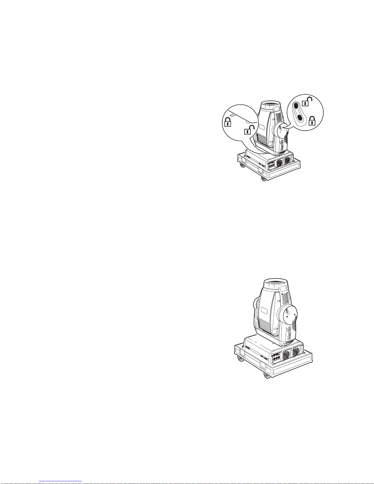
Transport locks. . . . . . . . . . . . . . . . . . . . . . . . . . . . . . . . . . . . . . . . . . . . . . . . . . . . . . . . . . . . . . . . . . . . . . . . . . . . . . . . . . 6
Cardboard box . . . . . . . . . . . . . . . . . . . . . . . . . . . . . . . . . . . . . . . . . . . . . . . . . . . . . . . . . . . . . . . . . . . . . . . . . . . . . . . . . . 6
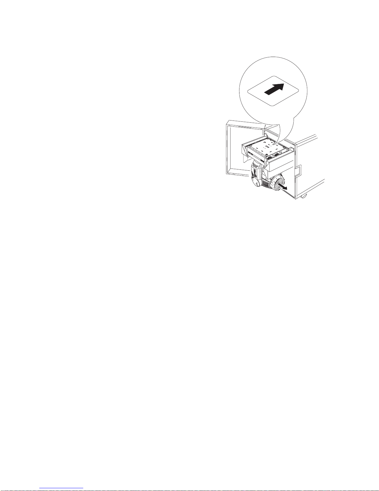
Single flight case. . . . . . . . . . . . . . . . . . . . . . . . . . . . . . . . . . . . . . . . . . . . . . . . . . . . . . . . . . . . . . . . . . . . . . . . . . . . . . . . . 6
Double flight case. . . . . . . . . . . . . . . . . . . . . . . . . . . . . . . . . . . . . . . . . . . . . . . . . . . . . . . . . . . . . . . . . . . . . . . . . . . . . . . . 7
AC POWER. . . . . . . . . . . . . . . . . . . . . . . . . . . . . . . . . . . . . . . . . . . . . . . . . . . . . . . . . . . . . . .8
Power supply . . . . . . . . . . . . . . . . . . . . . . . . . . . . . . . . . . . . . . . . . . . . . . . . . . . . . . . . . . . . . . . . . . . . . . . . . . . . . . . . . . . 8
Fuses . . . . . . . . . . . . . . . . . . . . . . . . . . . . . . . . . . . . . . . . . . . . . . . . . . . . . . . . . . . . . . . . . . . . . . . . . . . . . . . . . . . . . . . . . 9
Power connection. . . . . . . . . . . . . . . . . . . . . . . . . . . . . . . . . . . . . . . . . . . . . . . . . . . . . . . . . . . . . . . . . . . . . . . . . . . . . . . . 9
Reduced power function. . . . . . . . . . . . . . . . . . . . . . . . . . . . . . . . . . . . . . . . . . . . . . . . . . . . . . . . . . . . . . . . . . . . . . . . . . . 9
DATA . . . . . . . . . . . . . . . . . . . . . . . . . . . . . . . . . . . . . . . . . . . . . . . . . . . . . . . . . . . . . . . . . .10
Connecting fixtures. . . . . . . . . . . . . . . . . . . . . . . . . . . . . . . . . . . . . . . . . . . . . . . . . . . . . . . . . . . . . . . . . . . . . . . . . . . . . . 10
RIGGING. . . . . . . . . . . . . . . . . . . . . . . . . . . . . . . . . . . . . . . . . . . . . . . . . . . . . . . . . . . . . . . .11
CONTROL PANEL . . . . . . . . . . . . . . . . . . . . . . . . . . . . . . . . . . . . . . . . . . . . . . . . . . . . . . . . .12
Navigation. . . . . . . . . . . . . . . . . . . . . . . . . . . . . . . . . . . . . . . . . . . . . . . . . . . . . . . . . . . . . . . . . . . . . . . . . . . . . . . . . . . . . 12
DMX address and protocol setting . . . . . . . . . . . . . . . . . . . . . . . . . . . . . . . . . . . . . . . . . . . . . . . . . . . . . . . . . . . . . . . . . . 12
Tailoring performance. . . . . . . . . . . . . . . . . . . . . . . . . . . . . . . . . . . . . . . . . . . . . . . . . . . . . . . . . . . . . . . . . . . . . . . . . . . . 12
Readouts . . . . . . . . . . . . . . . . . . . . . . . . . . . . . . . . . . . . . . . . . . . . . . . . . . . . . . . . . . . . . . . . . . . . . . . . . . . . . . . . . . . . . 13
Service messages . . . . . . . . . . . . . . . . . . . . . . . . . . . . . . . . . . . . . . . . . . . . . . . . . . . . . . . . . . . . . . . . . . . . . . . . . . . . . . 14
Service utilities . . . . . . . . . . . . . . . . . . . . . . . . . . . . . . . . . . . . . . . . . . . . . . . . . . . . . . . . . . . . . . . . . . . . . . . . . . . . . . . . . 14
EFFECTS . . . . . . . . . . . . . . . . . . . . . . . . . . . . . . . . . . . . . . . . . . . . . . . . . . . . . . . . . . . . . . .16
Color. . . . . . . . . . . . . . . . . . . . . . . . . . . . . . . . . . . . . . . . . . . . . . . . . . . . . . . . . . . . . . . . . . . . . . . . . . . . . . . . . . . . . . . . . 16
Dimming and strobe . . . . . . . . . . . . . . . . . . . . . . . . . . . . . . . . . . . . . . . . . . . . . . . . . . . . . . . . . . . . . . . . . . . . . . . . . . . . . 16
Color temperature correction . . . . . . . . . . . . . . . . . . . . . . . . . . . . . . . . . . . . . . . . . . . . . . . . . . . . . . . . . . . . . . . . . . . . . . 16
Motorized zoom . . . . . . . . . . . . . . . . . . . . . . . . . . . . . . . . . . . . . . . . . . . . . . . . . . . . . . . . . . . . . . . . . . . . . . . . . . . . . . . . 16
Beam angles. . . . . . . . . . . . . . . . . . . . . . . . . . . . . . . . . . . . . . . . . . . . . . . . . . . . . . . . . . . . . . . . . . . . . . . . . . . . . . . . . . . 17
Motorized barn-doors . . . . . . . . . . . . . . . . . . . . . . . . . . . . . . . . . . . . . . . . . . . . . . . . . . . . . . . . . . . . . . . . . . . . . . . . . . . . 17
Aperture adjustment . . . . . . . . . . . . . . . . . . . . . . . . . . . . . . . . . . . . . . . . . . . . . . . . . . . . . . . . . . . . . . . . . . . . . . . . . . . . . 17
Pan and tilt . . . . . . . . . . . . . . . . . . . . . . . . . . . . . . . . . . . . . . . . . . . . . . . . . . . . . . . . . . . . . . . . . . . . . . . . . . . . . . . . . . . . 17
Speed control . . . . . . . . . . . . . . . . . . . . . . . . . . . . . . . . . . . . . . . . . . . . . . . . . . . . . . . . . . . . . . . . . . . . . . . . . . . . . . . . . . 17
OPTICS . . . . . . . . . . . . . . . . . . . . . . . . . . . . . . . . . . . . . . . . . . . . . . . . . . . . . . . . . . . . . . . .19
Color wheels. . . . . . . . . . . . . . . . . . . . . . . . . . . . . . . . . . . . . . . . . . . . . . . . . . . . . . . . . . . . . . . . . . . . . . . . . . . . . . . . . . . 19
Changing the front lens. . . . . . . . . . . . . . . . . . . . . . . . . . . . . . . . . . . . . . . . . . . . . . . . . . . . . . . . . . . . . . . . . . . . . . . . . . . 21
Changing the aperture ring. . . . . . . . . . . . . . . . . . . . . . . . . . . . . . . . . . . . . . . . . . . . . . . . . . . . . . . . . . . . . . . . . . . . . . . . 22
Installing the optional dimmer wheel. . . . . . . . . . . . . . . . . . . . . . . . . . . . . . . . . . . . . . . . . . . . . . . . . . . . . . . . . . . . . . . . . 22
ROUTINE MAINTENANCE . . . . . . . . . . . . . . . . . . . . . . . . . . . . . . . . . . . . . . . . . . . . . . . . . . . .24
The lamp. . . . . . . . . . . . . . . . . . . . . . . . . . . . . . . . . . . . . . . . . . . . . . . . . . . . . . . . . . . . . . . . . . . . . . . . . . . . . . . . . . . . . . 24
Cleaning . . . . . . . . . . . . . . . . . . . . . . . . . . . . . . . . . . . . . . . . . . . . . . . . . . . . . . . . . . . . . . . . . . . . . . . . . . . . . . . . . . . . . . 26
Firmware installation. . . . . . . . . . . . . . . . . . . . . . . . . . . . . . . . . . . . . . . . . . . . . . . . . . . . . . . . . . . . . . . . . . . . . . . . . . . . . 27
DMX PROTOCOL . . . . . . . . . . . . . . . . . . . . . . . . . . . . . . . . . . . . . . . . . . . . . . . . . . . . . . . . .29
16-bit protocol . . . . . . . . . . . . . . . . . . . . . . . . . . . . . . . . . . . . . . . . . . . . . . . . . . . . . . . . . . . . . . . . . . . . . . . . . . . . . . . . . 30
8-bit protocol . . . . . . . . . . . . . . . . . . . . . . . . . . . . . . . . . . . . . . . . . . . . . . . . . . . . . . . . . . . . . . . . . . . . . . . . . . . . . . . . . . 33
CONTROL MENU . . . . . . . . . . . . . . . . . . . . . . . . . . . . . . . . . . . . . . . . . . . . . . . . . . . . . . . . . .36
ADJUSTMENT SUBMENU . . . . . . . . . . . . . . . . . . . . . . . . . . . . . . . . . . . . . . . . . . . . . . . . . . . .40
DISPLAY MESSAGES . . . . . . . . . . . . . . . . . . . . . . . . . . . . . . . . . . . . . . . . . . . . . . . . . . . . . . .41
TROUBLESHOOTING . . . . . . . . . . . . . . . . . . . . . . . . . . . . . . . . . . . . . . . . . . . . . . . . . . . . . . .43
CIRCUIT BOARD CONNECTIONS . . . . . . . . . . . . . . . . . . . . . . . . . . . . . . . . . . . . . . . . . . . . . . .44
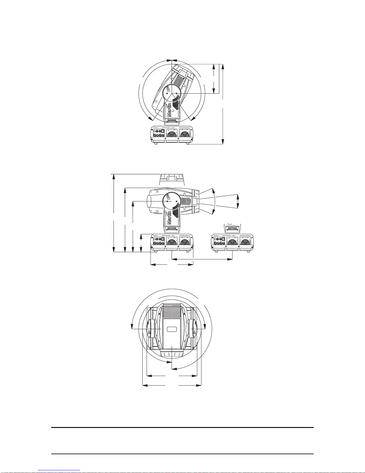
SPECIFICATIONS. . . . . . . . . . . . . . . . . . . . . . . . . . . . . . . . . . . . . . . . . . . . . . . . . . . . . . . . . .45

4 MAC 2000 Wash
I
NTRODUCTION
Thank you for selecting the MAC 2000 Wash. The MAC 2000 Wash is a 1200 Watt moving head wash light
that provides CMY color mixing, color correction (CTC), two color wheels (each with four removable colors),
a combined dimmer/shutter. 540° of pan and 267° of tilt. A motorized barn-door system and optional
dimmer wheel are available as a separately orderable accessory.
The MAC 2000 Wash has a Fresnel lens fitted as standard, and is also supplied with a PC lens and a
super-wide-angle lens. A motorized zoom provides beam angle ranges of 11° through to 40° (in the
standard Fresnel configuration), 12° through to 34° (with the PC lens fitted), or 66° through to 80° (with the
super-wide-angle lens fitted).
The MAC 2000 Wash is fitted with an electronic ballast that provides flicker-free operation and an
economical power-saving mode. The power supply unit is switchable to match 100 - 130 V or 200 - 250 V
local power supplies.
Note: This manual describes functionality available from version 1.7 of the MAC 2000 Wash
firmware. For the latest firmware updates, documentation, and other information about
this and all Martin Professional products, please visit the Martin web site at
http://www.martin.com.
MAC 2000 Wash safety information
Warning! This product is for professional use only. It is not for household use.
This product presents risks of lethal or severe injury due to fire and heat, electric shock, ultraviolet radiation,
lamp explosion, and falls. Read this manual before powering or installing the fixture, follow the safety
precautions listed below and observe all warnings in this manual and printed on the fixture. If you have
questions about how to operate the fixture safely, please contact your Martin dealer or call the Martin
24-hour service hot line at +45 70 200 201.
Protection from electric shock
• Disconnect the fixture from AC power before removing or installing the lamp, fuses, or any part, and when
not in use.
• Always ground (earth) the fixture electrically.
• Use only a source of AC power that complies with local building and electrical codes and has both overload
and ground-fault protection.
• Do not expose the fixture to rain or moisture.
• Refer any service operation not described in this manual to a qualified technician.
Protection from UV radiation and lamp explosion
• Never operate the fixture with missing or damaged lenses and/or covers.
• When replacing the lamp, allow the fixture to cool for at least 15 minutes before opening the fixture or
removing the lamp. Protect your hands and eyes with gloves and safety glasses.
• Do not stare directly into the light. Never look at an exposed lamp while it is lit.
• Replace the lamp if it becomes defective or worn out, or before usage exceeds the maximum service life.
Protection from burns and fire
• Never attempt to bypass the thermostatic switch or fuses. Always replace defective fuses with ones of the
specified type and rating.
• Keep all combustible materials (for example fabric, wood, paper) at least 1 meter (39 inches) away from the
fixture. Keep flammable materials well away from the fixture.
• Do not illuminate surfaces within 3 meters (10 feet) of the fixture.
• Provide a minimum clearance of 0.1 meters (4 inches) around fans and air vents.
• Never place filters or other materials over the lens.

Introduction 5
• The exterior of the fixture can get very hot. Allow the fixture to cool for at least 5 minutes before handling.
• Do not modify the fixture or install other than genuine Martin parts.
• Do not operate the fixture if the ambient temperature (Ta) exceeds 40° C (104° F).
Protection from injury due to falls
• Do not lift or carry the fixture alone.
• When suspending the fixture, verify that the structure can hold at least 10 times the weight of all installed
devices.
• Verify that all external covers and rigging hardware are securely fastened and use an approved means of
secondary attachment such as a safety cable.
• Block access below the work area whenever installing or removing the fixture.

6 MAC 2000 Wash
T
RANSPORTATION
Important! Release the transport locks before operating the fixture.
Included items
The MAC 2000 Wash is shipped in a cardboard box or in a
1 or 2 unit flight case that contains the following items.
• User manual
• 2 x 20 A main fuses (for use with 100-130 V local power
supply)
• 2 x 15 A main fuses (for use with 200-250 V local power
supply)
• 2 clamp attachment brackets
• XLR cable
Transport locks
The head and yoke may be locked for transportation and
service. The locks are shown in Figure 1. The fixture must be unlocked before operation.
Cardboard box
Instructions for removing models that have been shipped in a cardboard box are printed on the outside of
the box. The cardboard box is not designed for repeated use and for transportation of the fixture we strongly
recommend the use of one of our flight cases.
Single flight case
Unpacking the fixture
1 Remove the top of the flight case.
2 With one person on each side, lift the fixture out of the
bottom of the flight case.
3 Release the pan and tilt locks before operating.
Packing the fixture
1 Disconnect the fixture from power and allow it to cool.
2 Lock the head and yoke in the position shown in Figure 2.
3 Place the fixture in the bottom of the flight case. Place the
top section over the fixture without forcing.
Figure 1: Pan and tilt locks
Figure 2: Single unit transport position

Transportation 7
Double flight case
Unpacking
1 Open the flight case and pull the drawer all the way out.
2 Release the head (tilt) transport lock.
3 Install rigging hardware as described on page 11.
4 With one person on each side, lift the fixture out of the flight
case.
Packing
1 Disconnect the fixture from power and allow it to cool.
2 Turn the yoke parallel to the sides of the base with the tilt
lock closest to the back of the base.
3 Pull the transport drawer all the way out. With one person
on each side, place the fixture on the drawer with the
‘Front’ arrow pointing into the flight case.
4 Remove and stow rigging hardware. Coil and stow the
power cord in the door.
5 Tilt the head so that the lens points away from the door as
shown in Figure 3. Lock the head in the horizontal position.
Do not lock the yoke.
6 Slide the drawer all the way in without forcing. Close the flight case.
Setup for flight case testing
The double flight case has two slide-out arms from which the fixture can hang for testing and setting.
Though unnecessary, the pan and tilt reset can be cancelled by pressing [Menu] and [Enter] at the same
time.
1 Open the flight case and pull the drawer all the way out. Release the transport locks.
2 Pull the test arms out. Tilt the fixture up and over the test arms so that the handle cross-braces that are
second from the back rest on the arms. The fixture should rest at an angle.
3 Push the transport drawer into the flight case.
FRONT
Figure 3: Double unit transport position

8 MAC 2000 Wash
AC
POWER
WARNING! For protection from electric shock, the fixture must be grounded (earthed). The AC mains
supply shall be fitted with a fuse or circuit breaker and ground-fault protection.
Power supply
The MAC 2000 Wash is shipped configured for 200 - 250 V at 50/60 Hz, but can be manually switched to
accept either 100 - 130 V or 200 - 250 V power supplies.
Switching to match local power supply voltage
1 Ensure the fixture is not connected to power.
Lock the head vertically
2 Remove the four screws in the corners of the
display-side top panel and lift the panel clear.
Avoid strain on the panel ground (earth) cable
by supporting the panel.
3 The power supply switch is located in the
base unit at the end furthest from the display
(see Figure 5).
4 Set the switch to 115 V for a 100 - 130 V AC
power supply. Set the switch to 230 V for a
200 - 250 V AC power supply.
5 Replace the panel and screws. Remember to
unlock the head before using the fixture.
Figure 4: Removing display side top panel
230 115
Figure 5: Power supply switch

AC power 9
Fuses
The MAC 2000 Wash is supplied with:
• two 20 AT (time delay) main fuses for use with AC supplies of 100 - 130 volts.
• two 15 A main fuses for use with AC supplies of 200 - 250 volts.
Install the appropriate fuses in the holders near the power switch.
Power connection
Important! Connect the MAC 2000 Wash directly to AC power. Do not connect it to a dimmer system;
doing so may damage the fixture.
You may need to install a cord cap that fits your supply on the power cable. A 3-prong grounding-type plug
must be installed following the manufacturer’s instructions. The table shows some possible pin identification
schemes; if the pins are not clearly identified, or if you have any doubts about proper installation, consult a
qualified electrician.
To apply power, set the power switch on the base to the “I” position.
Reduced power function
The MAC 2000 Wash has an automatic power reduction function, which reduces the consumption to 700W
if the shutter/dimmer is closed for more than 10 seconds. This not only increases the lamp life, but also
further decreases the overall noise emission of the fixture.
Wire Color Pin Symbol Screw (US)
brown live L yellow or brass
blue neutral N silver
yellow/green ground green
Table 1: Cord cap connections

10 MAC 2000 Wash
D
ATA
Important! Never connect more than 1 data input and 1 data output.
The MAC 2000 Wash has both 3-pin and 5-pin XLR sockets for DMX input and output. The pin-out on all
sockets is pin 1 to shield, pin 2 to cold (-), and pin 3 to hot (+). There is no connection to pins 4 and 5.
The sockets are wired in parallel: both inputs connect to both outputs. For reliable data transmission and to
avoid damage to the fixture, however, use one input and one output!
Connecting fixtures
• Use shielded twisted-pair cable designed for RS-485 devices: standard microphone cable cannot transmit
control data reliably over long runs. 24 AWG cable is suitable for runs up to 300 meters (1000 ft). Heavier
gauge cable and/or an amplifier is recommended for longer runs.
• Never use both outputs to split the link. To split the serial link into branches use a splitter such as the Martin
4-Channel Opto-Isolated RS-485 Splitter/Amplifier.
• Do not overload the link. Up to 32 devices may be connected on a serial link.
• Terminate the link by installing a termination plug in the output socket of the last fixture. The termination
plug, which is a male XLR plug with a 120 ohm, 0.25 watt resistor soldered between pins 2 and 3, “soaks
up” the control signal so it does not reflect and cause interference. If a splitter is used, terminate each
branch of the link.
• Martin fixtures introduced before 1997 have reversed polarity data sockets (pin 2 hot and pin 3 cold). The
socket polarity is labelled. Use a phase-reversing cable (see “Accessories” on page 47) between the MAC
2000 Wash and any Martin device with reversed polarity.
Connecting the data link
1 Connect the DMX data cable from the controller to the MAC 2000 Wash’s 3-pin or 5-pin input (male) socket.
2 Using the sockets that match your data cable, connect the output of the fixture closest to the controller to
the input of the next fixture.
3 Insert a male 120 ΩXLR termination plug in the 3-pin or 5-pin output of the last fixture on the link.

Rigging 11
R
IGGING
The MAC 2000 Wash can be placed on stage or clamped to a truss in any orientation. The Fast-Lock
system enables quick and easy fastening of the clamp brackets in 4 positions as shown Figure 6.
Warning! Always use 2 clamps to rig the fixture. Lock each clamp with both 1/4-turn fasteners. The
fasteners are locked only when turned fully clockwise.
Warning! Attach an approved safety cable to the attachment hole in the base. Never use the carrying
handles for secondary attachment.
Clamping the fixture to a truss
1 Verify that the rigging clamps (not included) are undamaged and can bear at least 10 times the weight of the
fixture. Verify that the structure can bear at least 10 times the weight of all installed fixtures, clamps, cables,
auxiliary equipment, etc.
2 Bolt each clamp securely to a clamp bracket with an M12 bolt (grade 8.8 or better) and lock nut.
3 Align a clamp with 2 mounting points in the base. Insert the fasteners into the base and turn both levers a
full 1/4-turn clockwise to lock. Install the second clamp.
4 If the truss can be lowered, fixtures can be clamped on directly from the double flight case. If the fixture
must be lifted, block access under the work area. Working safely from a stable platform, hang the fixture on
the truss with the arrow towards the area to be illuminated. Tighten the rigging clamps.
5 Install a safety wire that can bear at least 10 times the weight of the fixture. The attachment point is
designed to fit a caribiner clamp.
6 Verify that the pan and tilt locks are released. Verify that there are no combustible materials or surfaces to
be illuminated within 1 meter (39 inches) of the fixture, and that there are no flammable materials nearby.
256
256
256
256
Figure 6: Clamp bracket positions
FRONT
Figure 7: Rigging hardware installation

12 MAC 2000 Wash
C
ONTROL
PANEL
The LED control panel is used to set the address and personalities, read lamp hours and other information,
calibrate effects, and run a test routine. Most of these functions may be performed remotely via the serial
link with the Martin MP-2 Uploader.
Navigation
The DMX address and any messages (see page 41) are displayed when the MAC 2000 Wash is turned on.
To enter the menu, press [Menu]. Press [Up] and [Down] to move within the menu. To select a function or
submenu, press [Enter]. To escape a function or menu, press [Menu].
See “Control menu” on page 36 for a complete list of the menu items.
Note: [Enter] must be pressed and held for a few seconds to enter the utilities menu.
DMX address and protocol setting
The DMX address, also known as the start channel, is the first channel used to receive instructions from the
controller. For independent control, each fixture must be assigned its own control channels. Two MAC 2000
Washs may share the same address, however, if identical behavior is desired. Address sharing can be
useful for diagnostic purposes and symmetric control, particularly when combined with the inverse pan and
tilt options.
Two DMX protocols, 8-bit and 16-bit, are available. The 8-bit mode uses 19 control channels and provides
full basic control. The 16-bit mode uses 2 additional channels to provide finer pan/tilt positioning.
Setting the DMX address and protocol
1 Press [Menu] to enter the main menu.
2 Press [Up] until AddR is displayed. Press [Enter]. To snap to channel 1, press [Enter] and [Up]. Scroll to
the desired channel and press [Enter].
3 Select PSET from the main menu and press [Enter]. Select 8bit or 16bt and press [Enter].
Tailoring performance
Movement
The MAC 2000 Wash provides six options for optimizing movement for different applications. The:
• Protocol setting (PSET)setting selects 8-bit or finer 16-bit control of pan and tilt.
• Pan and tilt invert (PATI)menu swaps and/or inverts pan and tilt.
• Pan/tilt speed (PTSP) menu provides 3 settings: FAST, NORM, and SLOW. NORM is best for most
applications. FAST provides better performance in applications where speed is most important. SLOW
provides the smoothest movement and is best in long-throw applications with slow movements through
narrow angles.
• Studio mode (STUd) setting optimizes all effects besides pan and tilt for speed or quietness.
• Shortcuts (SCUT)setting determines whether the color wheels always take the shortest path between two
static positions or oscillate between outer positions.
Tracking Response
The MAC 2000 Wash has a filter algorithm that looks at several position updates in tracking control mode
and calculates the ideal response for smooth movement. Tracking response is adjustable to compensate for
variations in controller performance. In most cases the default settings work well.

Control panel 13
If tracking mode movement is not satisfactory there are 2 parameters that can be adjusted. The first is
selected under PERS/TRAC/MOdE. The default, MOd1, is the best choice with controllers that
calculate intermediate positions at a steady rate. Begin by selecting the alternative, MOd2, which is better
if the intermediate positions stray significantly from the line of travel.
The second parameter is the number of position updates used to calculate speed. The level is adjustable
between 1 and 10 under PERS/TRAC/CAL. Increasing the number of samples increases the distance
over which speed is calculated, making movement smoother but less responsive to sudden changes.
Experiment for best results.
Display
The display intensity (dINT) setting controls display brightness. The display on/off setting (dISP)
determines whether the display remains on or extinguishes two minutes after the last key-press. To flip the
display, press [Up] and [Down] simultaneously.
Lamp
There are two settings that modify lamp control: Automatic Lamp On (ALON) and DMX Lamp Off (DLoF).
When ALON is off, the lamp remains off until a “lamp on” command is received from the controller. When
ALON is on, the lamp strikes automatically after the fixture is powered on. When ALON is set to DMX, the
lamp strikes automatically when the fixture receives DMX data, and it extinguishes 15 minutes after DMX
data is lost.
When ALON is set to either ON or DMX, the automatic lamp strike timing is staggered to prevent all lamps
from striking at once. The delay is determined by the fixture address.
If striking lamps from the controller, note that striking many lamps at once may cause a voltage drop large
enough to prevent lamps from striking or trip the main circuit breaker. Avoid this by programming a “lamp
on” sequence that strikes lamps one at a time at 5 second intervals.
Power to the lamp can be turned off from the controller if DMX Lamp Off (dLOF) is on.
Shutter dimming curves
Two dimming curves are available for the mechanical shutter system for adjusting intensity
(PERS/dICU). The default, dimmer curve 1, simulates the dimming of a tungsten lamp. Dimmer curve 2
applies a linear algorithm to intensity adjustment, that results in even adjustment across the whole dimming
range. Note that this setting has no effect on the optional dimming wheel, that uses a logarithmic dimming
curve.
DMX reset
The fixture can be reset from the controller if DMX reset (PERS/dRES) is ON.
Custom settings
The custom configuration function allows you to save and recall three sets of fixture settings. The savable
settings are DMX mode, pan/tilt speed, pan/tilt inverse and swap, DMX lamp off and reset, display settings,
shortcuts, studio mode, automatic lamp on, effects feedback, tracking algorithm, and tracking samples.
Readouts
Note: The MP-2 Uploader provides commands to display the time, temperature, and version readouts on
the fixture control panel.
Time
INFO/TIME provides readouts of fixture hours (HRS), lamp hours (L HR), and lamp strikes (L ST).
Under each item is a resettable (RSET) increment counter and a non-resettable counter for total
accumulated hours/strikes since fabrication (TOTL). To reset an increment counter, display it and then
press [Up] until it reads 0. (This may also be done remotely using the MP-2 Uploader.)

14 MAC 2000 Wash
Temperature
INFO/TEMP provides readouts of the head and base temperature in Celsius and Fahrenheit.
Firmware version
INFO/VER displays the version number of the installed firmware. The firmware version is also displayed
briefly at startup.
DMX
The DMXL menu shows the DMX start code (STCO) and DMX values received for each effect.
Service messages
The Service LED on the control panel lights under conditions that require fixture service, and there is a
message describing the service required. To display the message, select SMSG in the main menu. This
item is available only when the LED is lit. There are two service messages.
Replace lamp is displayed when the lamp counter exceeds 750 hours, which is the rated average life
for the HMI 1200 W/S lamp. The maximum service life is 125% of the average life, or 940 hours.
Fixture overheating is displayed when the head temperature exceeds 120° C (248° F).
Overheating is typically caused by dirty air filters, fans, or air vents; incorrect power supply settings, or a
defective fan.
Service utilities
Important! Enter must be held for several seconds to access the utilities menu.
Test sequences
TSEQ provides a general test of all effects that can be run without a controller. UTIL/PCBt provides
routines for circuit board testing that are for service use only.
Feedback toggles
An on-the-fly position correction system monitors the color wheels. If a position error is detected, the shutter
closes while the effect resets. This feature can be disabled by turning effects feedback (UTIL/EFFb) off.
The automatic pan/tilt position correction system may be temporarily turned off under UTIL/FEbA. The
off setting, however, is not saved and the system will be re-enabled the next time the fixture starts. If the
system cannot correct the pan/tilt position within 10 seconds, feedback is automatically disabled.
Adjustment
The adjustment menu (UTIL/Adj) provides manual control for making mechanical adjustments and is
used by Martin service technicians.
Calibration
The calibration menu (UTIL/CAL) provides utilities to define offsets in software that are relative to the
mechanical reset or home positions. This allows you to fine tune optical alignment and achieve uniform
performance between fixtures. Dimmer and zoom are calibrated to defined points. The other effects are
calibrated relative to an arbitrary reference fixture.
Default offset settings may be restored by selecting default offsets (UTIL/dFOF).
Calibrating effects
1 Apply power and strike the lamp.

Control panel 15
2 To calibrate the zoom, select UTIL/CAL/ZOOF and press [Enter]. The default value of 128 can be
adjusted up or down to move the diffuser lens relatively forward or back. Make any necessary adjustments
and press [Enter] to save the setting.
3 To calibrate the color wheels to an offset from their mechanically indexed position, select
UTIL/CAL/C1OF and press [Enter]. The default value of 128 can be adjusted up or down to move the
color wheel relatively forward or back from its indexed position. Make any necessary adjustments and press
[Enter] to save the setting. Repeat this procedure if necessary for color wheel 2 (C2OF).
4 To calibrate the optional dimmer wheel to an offset from its mechanically indexed position, select
UTIL/CAL/DIMW and press [Enter]. The default value of 128 can be adjusted up or down to move the
dimmer wheel relatively forward or back from its indexed position. Make any necessary adjustments and
press [Enter] to save the setting.
5 Pan calibration is most useful when multiple fixtures are stacked vertically. To calibrate, set zoom, iris, and
tilt position for easy one-over-the-other comparison and set each fixture to the same pan DMX value. Select
one fixture to be the reference fixture. On the other fixtures, select UTIL/CAL/P OF and press [Enter].
Adjust the offset as necessary to align the beam with the reference beam. Press [Enter] to save the setting.
6 Tilt calibration is most useful when multiple fixtures are arranged horizontally. To calibrate, set zoom, iris,
and pan position for easy side-by-side comparison and set each fixture to the same tilt DMX value. Select
one fixture to be the reference fixture. On the other fixtures, select UTIL/CAL/T OF and press [Enter].
Adjust the offset as necessary to align the beam with the reference beam. Press [Enter] to save the setting.
7 To calibrate the dimmer, select UTIL/CAL/D OF and press [Enter]. Hold a piece of paper over the
lens. Set the offset to 0 and then increase it until light is clearly projected onto the paper. Press [Enter] to
save the setting. Remove the paper.
8 To calibrate color mixing flags (cyan, magenta, yellow, and color temperature correction), project white
beams with no dimming and position them for easy comparison. On each fixture, including the reference,
select UTIL/CAL/C OF and press [Enter]. (This adds a defined amount of cyan.) Select one fixture to
be the reference. Adjust the offsets on the other fixtures to match the reference color. Press [Enter] to save
the setting. Repeat for M OF (magenta), Y OF (yellow), and CTOF (CTC).
Software upload
The software update mode is normally engaged automatically by the upload device. If this does not occur,
see “Firmware installation” on page 27.

16 MAC 2000 Wash
E
FFECTS
The MAC 2000 Wash is compatible with USITT DMX512 controllers. The fixture has two DMX operating
modes, 8-bit and 16-bit.16-bit mode requires two more DMX channels than 8-bit mode but provides more
precise pan/tilt positioning. All other functions are identical. See “DMX protocol” on page 29.
Color
The color mixing system uses continuous dichroic cyan, magenta, and yellow (CMY) color filters. It is a
subtractive system that removes color from white light. Inserting all three filters results in loss of light: for
maximum brightness, mix 2 colors at a time.
In addition, two color wheels are provided, each with four removable positions for dichroic glass color filters
and a position for a direct pass through of the beam.
Dimming and strobe
Two dimming systems are available - a built-in mechanical dimmer/shutter and an optional dimmer wheel
(orderable separately).
Shutter
The mechanical shutter system provides full-range 100 percent dimming, instant open and blackout,
random and variable strobe effects up to 10 Hz, and random and variable pulses in which the dimmer snaps
open and slowly dims or snaps closed and slowly opens. Two dimming curves are available; one that
simulates a tungsten lamp and another that provides linear dimming (see “Shutter dimming curves” on
page 13).
Optional dimmer wheel
A separately orderable dimmer wheel (P/N 62324018) that provides enhanced dimming can be installed in
place of color wheel 2. The dimmer wheel uses a logarithmic algorithm that, compared with the dimming
available from the shutter system, enables much finer and smoother dimming at the bottom end of the
dimming range.
If you use the dimmer wheel, it is recommended that you do not use the shutter system to control intensity,
and that the shutters be set to fully open (ensure that 255 is the default DMX value issued on the shutter
intensity channel from your controller). You can continue to use other shutter effects, such as the strobe.
The wheel is detected automatically by the fixture when installed. The installation procedure is described in
“Installing the optional dimmer wheel” on page 22.
Color temperature correction
The color temperature correction (CTC) system uses a continuous 0 - 178 mireds color filter that lowers the
color temperature from 6000 K to 2900 K.
Motorized zoom
The zoom lens widens the beam from 11° at full spot to 40° at full flood with the standard lens and aperture
ring fitted.

Effects 17
Beam angles
The following tables list the beam angles available with the standard 50 mm (2 in) aperture ring fitted. Note
that narrower beam angles can be achieved by fitting smaller aperture rings. Note that light buster mode
provides a high intensity spot with no diffusion and is engaged when the zoom channel is set to 100%.
For information about changing the lens see “Changing the front lens” on page 21.
Motorized barn-doors
A motorized barndoor system that attaches to the front of the fixture is available as a separately orderable
accessory. These barndoors can be rotated, or opened and closed using DMX control signals. Five DMX
channels are allocated for barndoor control irrespective of whether or not they are connected to the fixture.
We have done this to cover the possibility that you rig and begin programming your MAC 2000 Wash and
add barndoors to it later. If the DMX channels were not already assigned, you would have to re-patch your
console and therefore would lose any programming already completed.
Aperture adjustment
A 50 mm (2 in) aperture is fitted as standard in the optical path of the fixture just behind the zoom lens. This
works well with the standard Fresnel lens.
Inside the head of the fixture, three additional aperture rings are secured to the chassis by a thumbscrew.
When using the PC lens, the best beam characteristic is achieved by attaching the 45 mm aperture ring. For
instructions on changing the aperture ring see “Changing the aperture ring” on page 22.
Pan and tilt
The yoke pans 540° and the head tilts 267°. For maximum positioning accuracy, select 16-bit mode.
The pan/tilt speed (fast, norm, or slow) may be selected on the pan/tilt speed channel. Setting the pan/tilt
speed channel to “blackout” causes the shutter to black out the light while the head is moving.
Speed control
There are two ways to control the speed at which effects move from one static position to another. These
are known as tracking control and vector control and are selected on the Pan/Tilt Speed and Effect Speed
Standard Fresnel lens Beam angle
Light buster mode 11°
Zoom narrow 15°
Zoom wide 40°
PC lens Beam angle
Light buster mode 12°
Zoom narrow 12°
Zoom wide 34°
Super-wide-angle lens Beam angle
Light buster mode 66°
Zoom narrow 70°
Zoom wide 80°

18 MAC 2000 Wash
Channels. These channels are independent so you may, for example, combine a vector control pan
movement with a tracking control color fade.
In tracking mode, speed is determined by the cross-fade time. The controller continuously sends small
position changes that the fixture “tracks.” To enable tracking mode, set the relevant speed channel to a
tracking value. Note that in addition to enabling tracking control, some tracking values also provide
overrides of the menu settings.
In vector mode, speed is set directly on a speed channel. The cross-fade time must be 0. Vector control
provides a way to set speed on controllers that do not have programmable fade times and results in smooth
movement regardless of the cross-fade time or the controller’s processing power.

Optics 19
O
PTICS
This chapter describes the elements of the optical path and changes that can be made to them. It covers
the:
• Color wheel and filters, below
• Front lenses, on page 21
• Aperture rings, on page 22
• Optional dimmer wheel, on page 22
Color wheels
The following is a view of the color wheels as seen from the lamp.
Color wheel 1
Color wheel 1 provides the following four removable dichroic color filters and an open position.
1 Position 1 - Green 203 (P/N 46402006)
2 Position 2 - Blue 108 (P/N 46402007)
3 Position 3 - UV Transmitter (P/N 46402008)
4 Position 4 - Half Minus Green (P/N 46402009)
5 Position 5 - Open
Color wheel 2
Color wheel 2 provides the following four removable dichroic color filters and an open position:
1 Position 1 - Red 308 (P/N 46402005)
2 Position 2 - Orange 306M (P/N 46402004)
3 Position 3 - Green 208 (P/N 46402002)
4 Position 4 - Blue 102 (P/N 46402001)
5 Position 5 - Open
Fixture top
Fixture bottom
Wheel 1 Wheel 2
1
2
3
4
12
3
4
Open

20 MAC 2000 Wash
Changing color filters
Additional color filters can be ordered from Martin.
To ensure the best performance, lenses must be fitted with the coated surface away from the lamp.
To change a color filter:
1 Disconnect the fixture from power and allow it to cool.
2 Lock the head horizontally with the top cover up.
3 Remove the top cover of the fixture using a flathead screwdriver to unlock the four quarter-turn screws.
4 Remove the two screws holding the color wheel module in place using a Philips screwdriver. Disconnect the
cables and lift the whole module out of the fixture.
5 Remove filters using your fingers and a soft cloth to protect the lens.
TOP
TOP
29 / 28 10
9
Cable connections
Table of contents
Other Martin Professional Spotlight manuals
Popular Spotlight manuals by other brands

Larson Electronics
Larson Electronics LED10W-1SCB instruction manual

Tri-Tronics
Tri-Tronics NIGHTRAZOR owner's manual

AGPtek
AGPtek SLO1B user manual

Lucci Fresco
Lucci Fresco SENTINEL 2 LIGHTS SPOT LIGHT installation instructions

Elation
Elation PROTHEUS HYBRID user manual

Sealey
Sealey AK436.V3 instructions

Dorcy
Dorcy 41-1097 User instructions

Prilux
Prilux Kenia 504775 quick start guide

olympia electronics
olympia electronics GR-297/60L/180 manual

thomann
thomann STAIRVILLE Outdoor Stage PAR 12 X 3W Tri user manual

Hinkley
Hinkley 1536BZ-LMA installation instructions

Spotlight
Spotlight Black Gun W 400 user manual