CANTO USA A10857190 User manual

V 1.1 2/25/21 1
Innovative Lighting Products
1092 West Atlanta Street, SE • Suite 600 • Marietta, GA 30060 • 888-252-5912 • tech[email protected] • cantousa.com
CANTO®FOLLOWSPOT
OPERATING INSTRUCTIONS
FOR THE NORTH AMERICAN REGION 120/208V 60 HZ
MODELS COVERED
A10857190 Tango 1500 MSR FF 120V, Black
We hope that this product will meet your requirements, but if for any reason this should not be the case, we ask that you
contact us directly at 888-252-5912 to help address your needs. We wish to provide all of our customers with the best
quality products available. The product you purchased has been manufactured with maximum care in construction and
choice of components. If you have received your equipment damaged for any reason beyond our control, please contact
your local dealer who supplied the product to you within 72 hours after receiving our product.

Innovative Lighting Products
Followspot Operating Instructions
V 1.1 2/25/21 2
1092 West Atlanta Street, SE • Suite 600 • Marietta, GA 30060 • 888-252-5912 • tech[email protected] • cantousa.com
TABLE OF CONTENTS
Important Safety Norms .................................................................................... page 3
Check packing content ...................................................................................... page 4
Mounting the spigot .......................................................................................... page 4
Mounting the color changer .............................................................................. page 5
Mounting the iris diaphragm .............................................................................. page 5
Shutter blades .................................................................................................. page 6
Adjusting the yoke ............................................................................................ page 6
Wiring ............................................................................................................ page 6
Voltage ........................................................................................................... page 6
Frequency ....................................................................................................... page 7
Fuse ............................................................................................................... page 7
Mounting or replacing the lamp ......................................................................... page 7
Operation of the followspot ............................................................................... page 8
Lamp settings and alignment .............................................................................. page 8
Focusing ......................................................................................................... page 9
Black-out mechanical dimmer ............................................................................. page 9
Cleaning and maintenance ............................................................................... page 9
Spare parts ..................................................................................................... page 10
Warranty ........................................................................................................ page 10

Innovative Lighting Products
Followspot Operating Instructions
V 1.1 2/25/21 3
1092 West Atlanta Street, SE • Suite 600 • Marietta, GA 30060 • 888-252-5912 • tech[email protected] • cantousa.com
CAREFULLY READ THE OPERATING INSTRUCTIONS BEFORE USING THIS FIXTURE.
The instructions given here ensure safe usage of this product. User’s failure to comply with the installation, operation,
maintenance and safety procedures mentioned in this manual as well as those generally applicable to lighting equipment,
may cause the fixture not to perform as expected.
CantoUSA accepts no liability for direct, indirect, incidental, special, or consequential damages resulting from the customer’s
failure to follow the installation, operating, maintenance and safety procedures described in this manual. These limitations
extend to damages for personal injury, property damage, loss of operation, loss of profits, loss of product or loss of time,
whether incurred by the customer, the customer’s employees, or third-party vendors or users.
Apart from the instructions given in this manual, all relevant safety and health standards of the appropriate local city and
state electrical / safety directives must be complied with.
PLEASE SEE OUR GENERAL TERMS OF SALE AND WARRANTY CARD PROVIDED WITH YOUR NEW EQUIPMENT OR
EMAIL US FOR A COPY AT ANY TIME.
IMPORTANT SAFETY NOTES
This product may reach high temperatures depending on the model ordered. Avoid any direct contact with its metal exhaust parts.
*NEVER WORK INSIDE AN OPERATING UNIT WITHOUT IT BEING COOLED AND UNPLUGGED FROM
POWER SOURCE. NEVER EVER WORK INSIDE A UNIT THAT IS TURNED ON.
*WARNING: HIGH VOLTAGE IGNITION (MSR/MSD ONLY)
U.V. RAYS
The lamps used on the discharge models (Canto 575, 700, 1200, 1500, and 2000 MSR / MSD) emit UV rays. Protect
your eyes and never look directly at the source of light with unshielded eyes.
*These products use fan-assisted ventilation. Make sure you do not cover the fan or obstruct the airflow at any time. Please
make sure the fan(s) are working correctly at all times. Should you detect even the slightest malfunction, switch the fixture off
immediately and carry out the necessary servicing. Replace the fan if necessary.
*This product is rated at IP 20 and is therefore designed for interior use only. For details on maximum ambient operating
temperature and minimum distance from flammable objects as well as maximum tilt angle, please refer to the instructions as
is indicated on the product label.
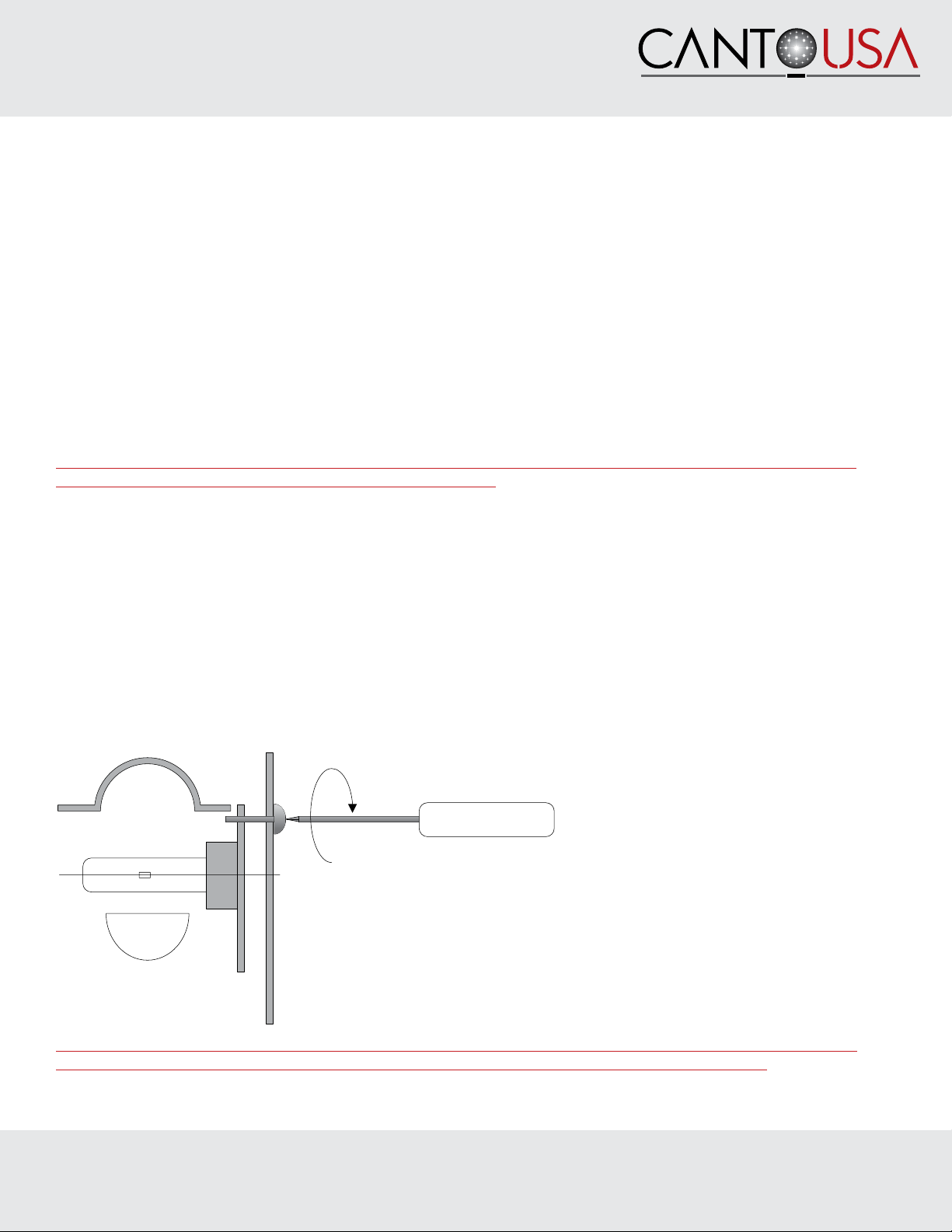
*Replace the lamp, reflector or any lenses if damaged or deformed by heat. Make sure the lamp is cold before attempting
to remove it. To perform a correct installation of the lamp, please refer to the lamp manufacturer’s instructions included in the
lamp box and the relevant chapters in this manual.
*Repair or replacement of any component of this product must be carried out exclusively by professional personnel in
conformity with the relevant safety and health standards and only with original CantoUSA components.
*Replacement of any part of the wiring system must be carried out exclusively by professional personnel in compliance
with the original wiring diagram and with components identical or compatible with those originally used in the products
construction. Installation of this product must be exclusively carried out by professional personnel in compliance with the
safety procedures in force in the country where the product is being used.

Innovative Lighting Products
Followspot Operating Instructions
V 1.1 2/25/21 4
1092 West Atlanta Street, SE • Suite 600 • Marietta, GA 30060 • 888-252-5912 • tech[email protected] • cantousa.com
BEFORE YOU GET STARTED, PLEASE READ THIS INSTRUCTION MANUAL
COMPLETELY.
CHECKING BOX CONTENTS:
Upon opening the boxes, please make sure the boxes contain the following items:
FOLLOWSPOT:
A. In case you bought just the followspot – item #A10857190 Canto 1500msr FF 120V
1. Fixture:
a. Followspot
b. Iris diaphragm
c. 7 color magazine – integral, not mounted
2. PSU:
a. 120V separate electronic ballast unit
B. In case you bought the complete kit – item #KA10857190 packed in a flight case:
a. Followspot
b. Electronic ballast unit
c. Iris diaphragm
d. 7 color magazine
e. Heavy duty followspot tripod
f. Philips MSR Gold 1500/2 FastFit lam PGJX50, 7500K 750 hours
TRIPOD STAND:
Tripod – May or may not include casters for the tripod. Casters are an accessory that can be purchased.
TRIPOD MOUNTING:
Make sure the tripod you have chosen for the Tango has a suitable head accomodate the TANGO Stirrup (DIN plate)
CantoUSA strongly recommends you use the Heavy-duty tripod, which has been specifically designed for the TANGO range
of followspots and which is fitted with a large holding base and a fluid head which grants a totally smooth and wobble free
operation of your followspot
Mount the followspot on the tripod. Make sure the structure you are fixing the product to can withstand the product load
(see above list and product label).

Innovative Lighting Products
Followspot Operating Instructions
V 1.1 2/25/21 5
1092 West Atlanta Street, SE • Suite 600 • Marietta, GA 30060 • 888-252-5912 • tech[email protected] • cantousa.com
MOUNTING THE COLOR CHANGER:
This section only applies in case you bought the followspot only. In case you purchased the kit version the color changer
comes already fitted to the followspot. In order to perform this operation you will need have a Phillips screw driver with a
mimimum length of 6 1/2” (16cm)
1. Mount color filters on the color changer units. See relevant instructions supplied with the color changer.
2. Slightly unscrew the M4 screws fitted in each one of the M4 brass inserts on the front plate of the followspot
3. Position the color changer unit on the front plate of the follow spot, making sure that the color levers are
positioned on the righthand side of the followspot when viewed from behind and hang it to the previously
positioned screws.
4. Release the color filters of the color changer in order to have access to the screws and tighten them.
5. Ensure the color changer unit is secure, and all 4 screws are tight.
NOTE: Do not discard the removed color runners and color frame, as they will be needed when the followspot is returned to
its original standard.
MOUNTING THE IRIS DIAPHRAGM:
The iris diaphragm supplied with the followspot has 24 leaves to size the beam from a maximum aperture of 8º to minimum
of 4º.
1. Using a Phillips screw-driver remove the two phillips screws from the sides of the iris plate.
2. Slide the diaphragm in the gate area.
3. Tighten the screws.
IMPORTANT NOTICE: DO NOT LEAVE THE IRIS CLOSED FOR OVER:
• 10 minutes while the lamp is on.
Use the front dowsing iris to cut “off” the light should you require to have the lamp on with no beam projecting onto the stage.
FAILURE TO COMPLY WITH THE ABOVE NOTICE MAY CAUSE THE IRIS AND THE FOLLOWSPOT TO SUFFER
MAJOR HEAT DAMAGE AND WILL INVALIDATE THE PRODUCT WARRANTY.

Innovative Lighting Products
Followspot Operating Instructions
V 1.1 2/25/21 6
1092 West Atlanta Street, SE • Suite 600 • Marietta, GA 30060 • 888-252-5912 • tech[email protected] • cantousa.com
ADJUSTING THE YOKE:
This followspot is provided with a yoke balancing adjustment. The balancing point is factory set for the standard product
configuration supplied with color changer. However, should you need to adjust the balancing, please follow the procedure
here below.
Two persons, one at the front and one at the back of the followspot are needed to perform this operation
1. Mount the followspot on the tripod stand with all relevant accessories attached.
2. Using a Phillips screw driver, loosen the 3 (M5) screws on each side of the yoke.
3. Gently slide the followspot backwards or forwards to the required position.
4. Make sure the yoke is correctly aligned horizontally.
5. Tighten the 6 (M5) screws
WIRING:
Before being connected to power, please make sure that the unit is outfitted with a suitable plug. Make sure the plug conforms
to the lamp power load. Ensure the plug conforms to the relevant local safety requirement and UL electrical standards.
• Make sure the plug you are fitting withstands the lamp power load.
• This fixture must be grounded
• To perform a correct wiring, please note that the cores in this mains lead are color-coded as follows:
Ground: green+yellow – Neutral: blue - Hot: brown
In case the colors of the wires do not correspond to the color of the connection points on your plug, please proceed as follows:
• The green or green and yellow wire is ground and must be connected to the connection point marked with the
letter E or with the symbol or colored in green or in green+yellow
• The blue wire is neutral and must be connected to the connection point marked with the letter N or with the
symbol or colored in black
• The brown wire is hot and must be connected to the connection point marked with the letter L or with the
symbol or colored in red
Before you finally position this product for use, temporarily connect it to a properly fused power supply to check the lamp
works correctly.
VOLTAGE:
Before operating this unit, please refer to the product label mounted at the back of the fixture to check that you are operating
with the correct voltage.
The Tango 1500 can only be operated at 120V.

Innovative Lighting Products
Followspot Operating Instructions
V 1.1 2/25/21 7
1092 West Atlanta Street, SE • Suite 600 • Marietta, GA 30060 • 888-252-5912 • tech[email protected] • cantousa.com
FREQUENCY:
Frequency on this product is automatically selected by the electronic PSU (50/60Hz)
FUSE:
The PSU is fitted with a 20A 6.3x32 UR fast fuse. In case a replacement is needed, always make sure you use a suitable
and compatible fuse. The fuse is located on the ballast unit.
MOUNTING/REPLACING THE LAMP:
Although this unit is supplied with a double-pole micro-switch for safety, we strongly recommend that you disconnect the
followspot from main power before installing the lamp.
THE CANTO TANGO 1500 MSR FF CAN BE OPERATED ONLY WITH:
1500W 6000K Philips 1500 MSR Gold Fast Fit PGJX50 750 hrs
1500W 7500K Philips 1500 MSR Gold/2 Fast Fit PGJX50 750 hrs
CAUTION: ONLY PERFORM SERVICING AFTER THE UNIT HAS BEEN COOLED DOWN, UNPLUGGED
FROM POWER SOUCRCE, AND OFF FOR 30 MINUTES.
NEVER REPLACE A HOT LAMP.
a. When replacing a lamp use a proper thermal protection for your hands (ex. gloves) in case the lamp is still hot.
b. Protect the lamp from abrasion and scratches. Do not install or use a cracked or broken lamp. In case a lamp cracks
or breaks, disconnect from the power supply, allow the unit to cool and remove/replace the broken lamp.
c. Never touch the lamp bulb with bare hands. Oil and grease can contaminate the quartz surface and reduce the
lamp performance and life of the lamp and may cause non-passive failure.
d. Pull plastic sleeve protection off and then install the lamp.
e. Using a flathead screw driver open the lamp-holder panel positioned on the left-hand side of the lamp house by turning
(counter clockwise) the two ¼ turn fasteners.
f. Remove the panel.
g. Remove the lamp (if operating a replacement) by holding the ceramic base and turning it until the lamp is dislodged
h. Place the new lamp in by holding the ceramic base and turning it until the base is locked in position.
i. Reposition the lamp holder panel by turning clockwise the two ¼ turn fasteners
Canto USA declines any responsibility on poor performance of the unit or damages to the inner components in case a non
compatible lamp is used.

Innovative Lighting Products
Followspot Operating Instructions
V 1.1 2/25/21 8
1092 West Atlanta Street, SE • Suite 600 • Marietta, GA 30060 • 888-252-5912 • tech[email protected] • cantousa.com
OPERATION OF THE FOLLOWSPOT:
1. Plug the followspot to the electronic PSU. Please note that each followspot has been factory tested with relevant
PSU. Both units are recognized by a serial number (on the outer box, on the units and on the front cover of the
instruction manual). Make sure you match each followspot to the relevant PSU.
2. Connect the PSU to your 120 volt power supply.
3. Turn to the right (1/4 turn) the on/off selector on the PSU (fans will start working).
4. A RED LIGHT comes up from inside the ballast (visible from the ventilation slots beside the on/off selector
5. WAIT UNTIL THE RED LIGHT TURNS GREEN AND FINALLY CYAN (GREEN+BLUE) (3/5 seconds)
6. Turn to the right (1/4 turn) the on/off selector positioned at the back of the luminaire (lamp is on).
The lamp will only switch on once the green light in the ballast is on. Should you have waited too long the PSU will not have
found the lamp when trying to strike it. The ballast will try for 10 times and then stop, assuming no lamp is inserted after
which the lamp will not go on. In this case please switch the PSU off and start again
CAUTION: ONLY PERFORM SERVICING AFTER THE UNIT HAS BEEN COOLED DOWN, UNPLUGGED
FROM POWER SOUCRCE, AND OFF FOR 30 MINUTES.
LAMP SETTINGS AND ALIGNMENT:
For an optimum performance of the followspot, lamp alignment must be checked and performed each time a new lamp is
fitted or an old lamp is replaced. Please proceed as follows:
1. Turn the followspot on and project the light on a flat surface about 3-6 feet away.
2. Completely de-focus the zoom so that you can see the lamp projected on the surface.
3. Close the douser to a slightly bigger size than the height of the lamp. You should see a circle of light and the
image of the lamp on the surface.
4. If the lamp is not exactly centered in the circle of the light, set the alignment by loosening/tightening one of the
three adjustment screws positioned at the bottom of the lamp holder block until the lamp is aligned.
CAUTION: ADJUST EACH SCREW VERY SLOWLY IN ORDER NOT TO CAUSE THE LAMP TO TOUCH THE
OPTICAL SYSTEM. THIS WILL CAUSE BOTH THE LAMP AND THE FRONT LENS TO EXPLODE.
Once the alignment is correct, you can begin using the followspot.

Innovative Lighting Products
Followspot Operating Instructions
V 1.1 2/25/21 9
1092 West Atlanta Street, SE • Suite 600 • Marietta, GA 30060 • 888-252-5912 • tech[email protected] • cantousa.com
FOCUSING:
This fixture features a variable beam angle from 4º to 8º. The variable beam is altered by adjusting the front and rear zoom
lenses in relation to each other. The front lens defines the beam spread, the rear lens then focuses the degree of ‘softness’ or
‘hardness’ of the beam edge or shutters.
BLACK-OUT MECHANICAL DIMMER (DOUSER):
Your followspot is fitted with an adjustable mechanical dimmer (douser) to dim and finally blackout the light. The black‐out
mechanical dimmer is located between the front of the lens tube and the color changer. A screen printing is provided on
the upper front cover of the lens tube (near the lever operating the douser) to help you position the douser at the required
dimming position (0% - 100%)
CLEANING AND MAINTENANCE:
To ensure maximum performance of the product, a regular maintenance service should be carried out. Please make sure the
product is cold and disconnected from power supply when doing this. Use a clean cloth and non-abrasive glass cleaner like
denatured alcohol.
GENERAL MAINTENANCE:
Clean all reflective parts such as reflector, mirrors, and lenses as necessary. Check the lamp and the lenses and replace
any visibly damaged component. Clean air ducts and fans in order to allow proper ventilation activity on the product, we
recommend vacumming NOT blowing. Check internal and external wiring and replace any cable which shows wear and tear.
WARNING: NEVER USE AMMONIA, BLEACH, VINEGAR, OR WINDOW CLEANER, WHICH CAN HARM OUR
COATED LENSES.
CLEANING OF OPTICAL COMPONENTS:
LAMP HOUSE LENS ASSEMBLY:
Open the lens compartment by removing the two M4 Phillips head screws on the top of the lamp house. To remove the
lens/reflector assembly block, remove the two M5 Phillips head screws in front on both sides. Clean the lens/mirror with
a soft cloth.
ZOOM LENSES:
Slide the bottom access door(s) of the lens tube forward or back to access the optics and clean with a soft microfiber cloth.

Innovative Lighting Products
Followspot Operating Instructions
V 1.1 2/25/21 10
1092 West Atlanta Street, SE • Suite 600 • Marietta, GA 30060 • 888-252-5912 • tech[email protected] • cantousa.com
SPARE PARTS
All components are available as spare parts. We strongly recommend you always use original components as spare parts.
Please call our technical team at 888-252-5912 should you need to order and/or replace any parts on your unit.
WARRANTY
Our warranty covers all structural and manufacturer defects for three years from the date you purchased this product and
10 years on any LED array. In case of any issues, we strongly recommend you call us at 888-252-5912 or contact the
local dealer who supplied the product to you. In any case, please report the serial number of the product when making a
warranty claim.
AVAILABLE ACCESSORIES
3130180 Philips MSR 1500 Fast Fit
A20105107 Spare 7 color changer magazine
A20100710 Spare iris diaphragm
A20102311 HD Black followspot tripod with fluid head
A20107190 Flightcase with braking wheels, stackable
V90MLRT100FR Braking wheel (1pc) for flight case
EXTW-0001 Extended warranties are available up to 2 additional years past the standard 3 year warranty period.
Canto USA reserves the right to modify this document without prior notice.
Table of contents
Other CANTO USA Spotlight manuals
Popular Spotlight manuals by other brands

Sea-Dog
Sea-Dog Deluxe ASA Halogen Spot/Flood Light Installation & operation instructions

North Light
North Light FL-P-15W quick guide

LIVARNO LUX
LIVARNO LUX HG03444B Assembly, operating and safety instructions

Net Media
Net Media NM-IRLAMP Specifications

Eton
Eton ROAD TORQ datasheet

Enigma
Enigma TS-00028 instruction manual