Martin P3 PowerPort 1000 IP Rental User manual

P3 PowerPort 1000 IP Install
SERVICE MANUAL
Revision A, 10-26-2017

Service manual
2 of 15P3 PowerPort 1000 IP Install - Revision A, 10-26-2017
Table of contents
General information ............................................................................................................................................ ...3
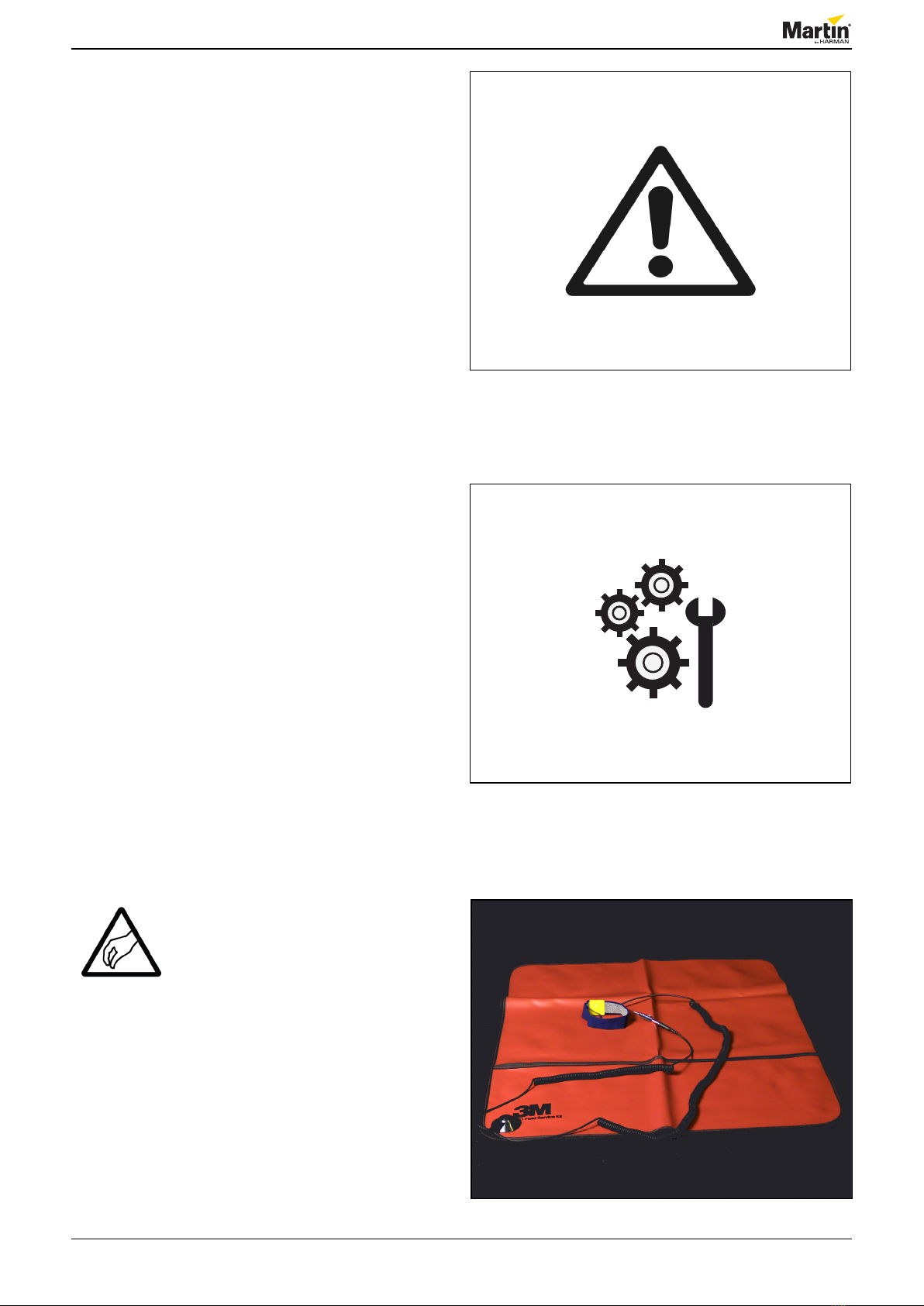
Safety instructions .................................................................................................................................................................................3
Tools ........................................................................................................................................................................................................3
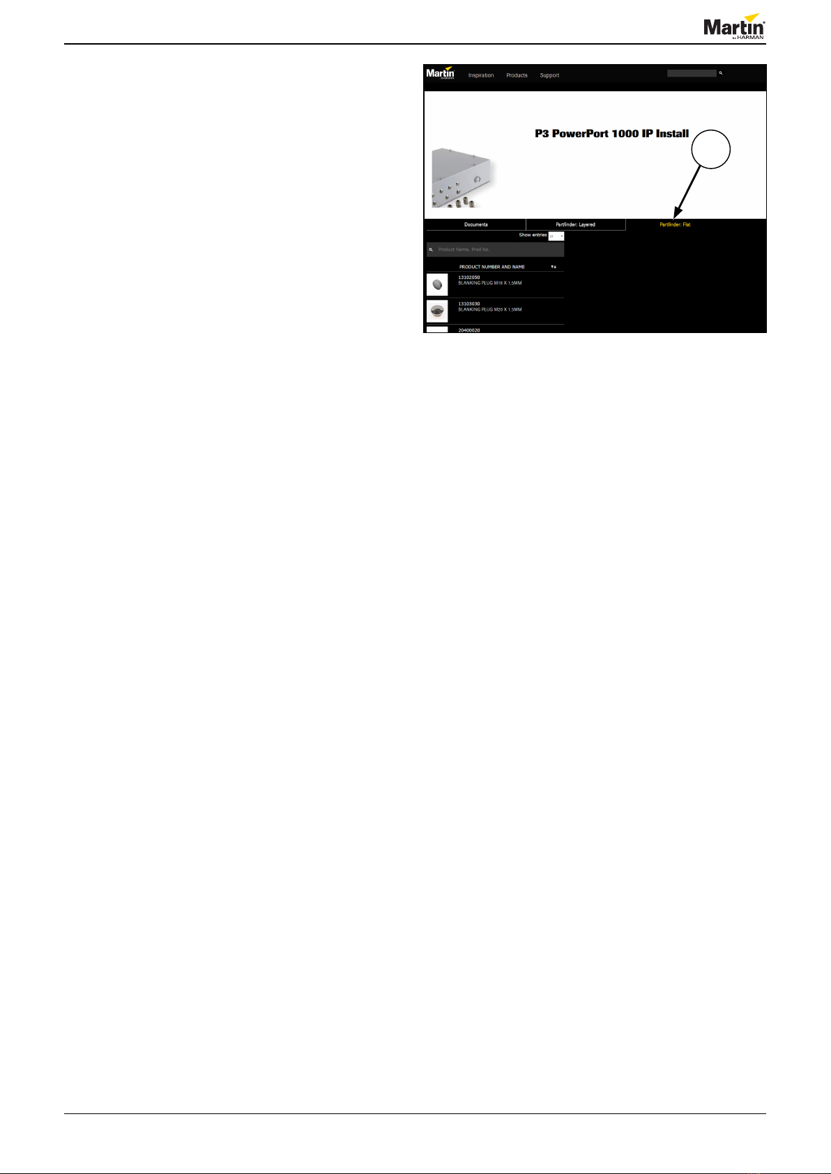
Spare parts ..............................................................................................................................................................................................4
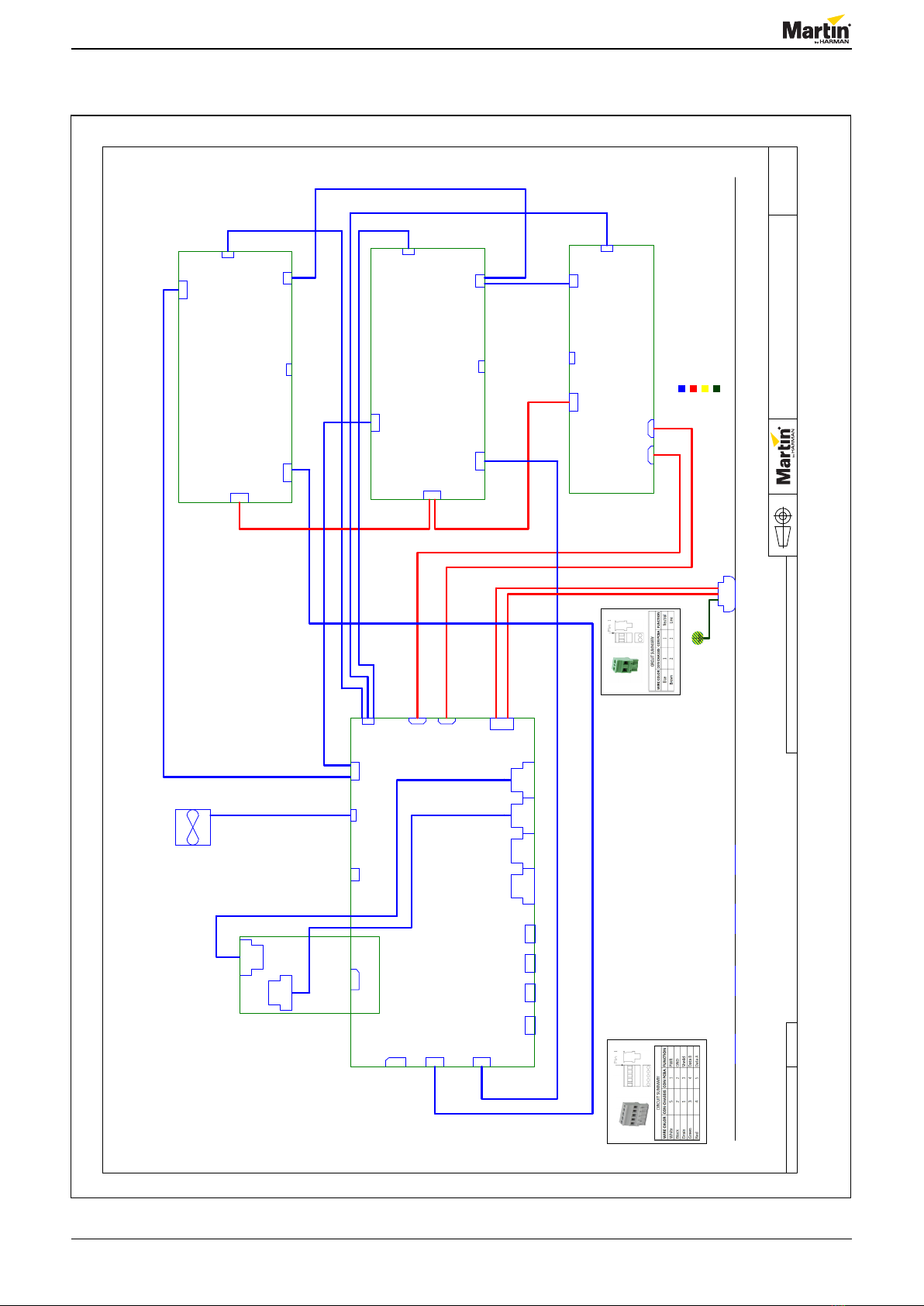
Wiring diagram .................................................................................................................................................... ...5
Repair and replacement...................................................................................................................................... ...6
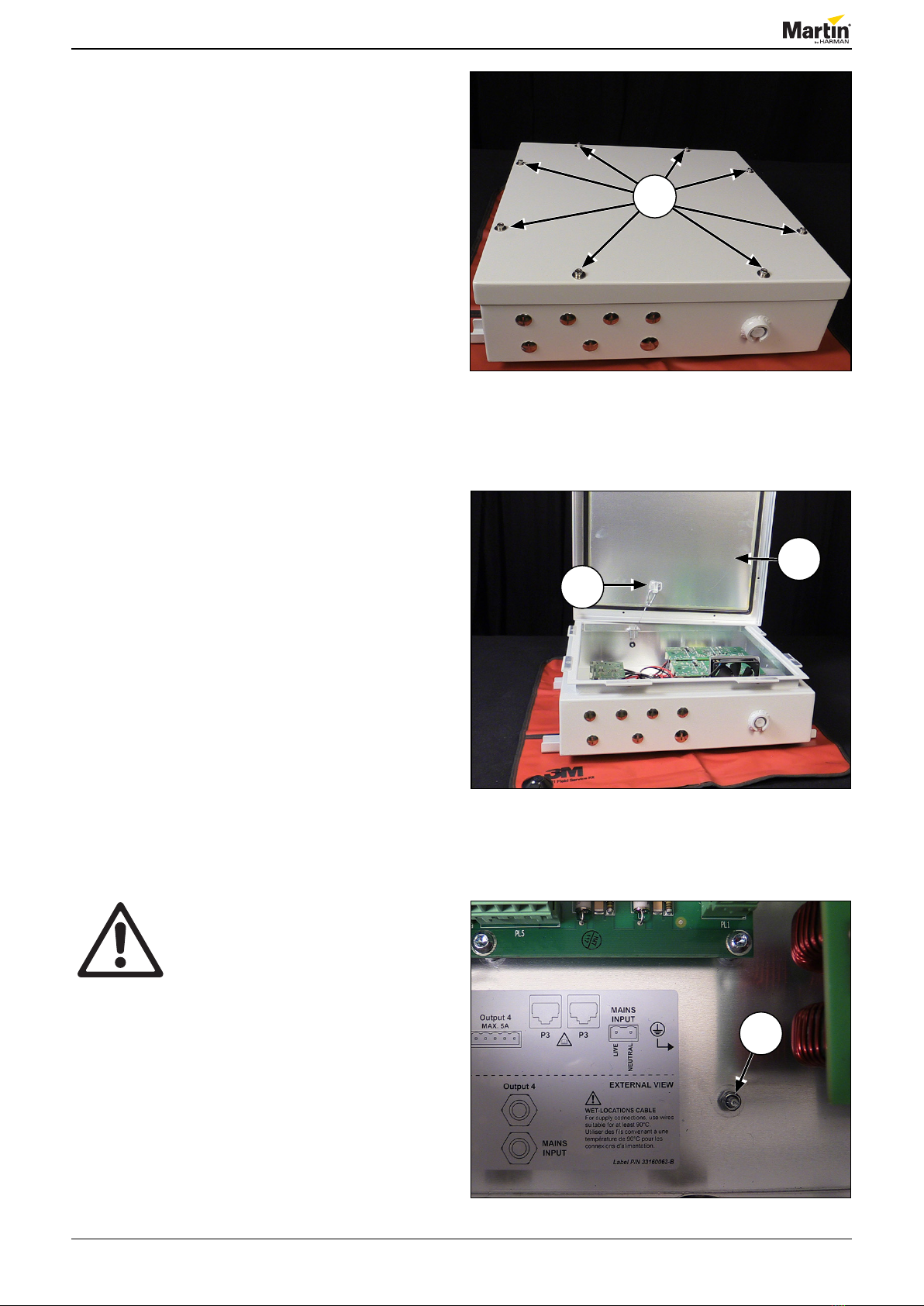
Opening the lid........................................................................................................................................................................................6
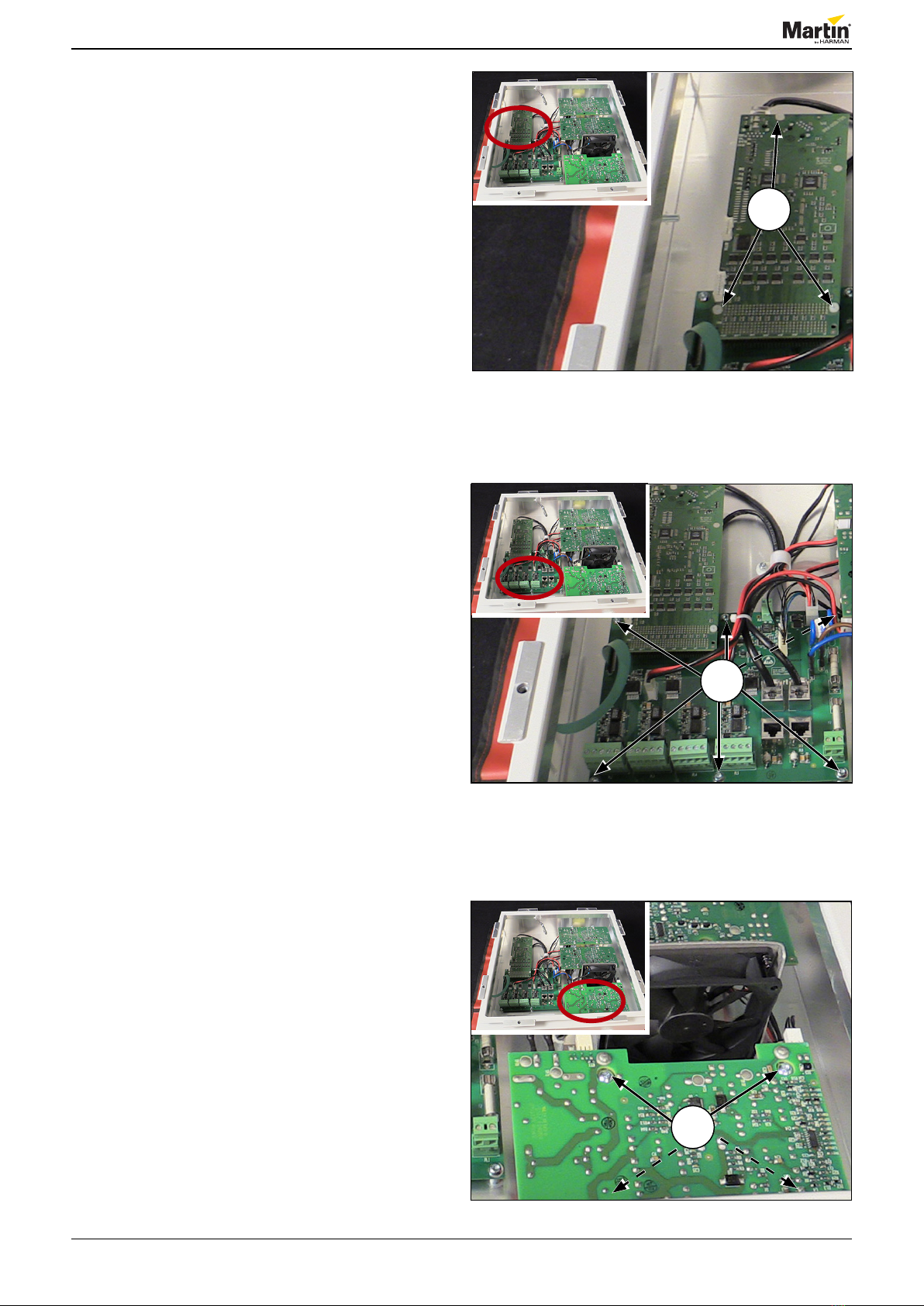
Replacing the controller PCBA..............................................................................................................................................................7
Replacing the transceiver PCBA...........................................................................................................................................................7
Replacing the power supply PCBA.......................................................................................................................................................7
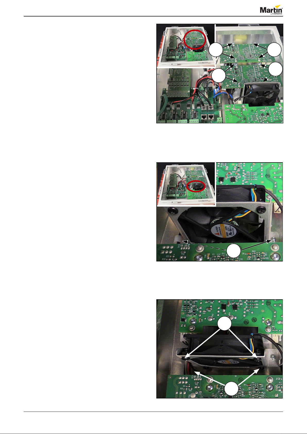
Replacing the DC/DC PCBA...................................................................................................................................................................8
Replacing the fan....................................................................................................................................................................................8
Replacing the display panel ..................................................................................................................................................................9
Updating software ................................................................................................................................................................................12
Maintenance....................................................................................................................................................... ...13
Cleaning the product............................................................................................................................................................................13
Cleaning the pressure relief valve...................................................................................................................................................................... 13
Conditions .............................................................................................................................................................................................14
Maintenance schedule .........................................................................................................................................................................14

Service manual
3 of 15P3 PowerPort 1000 IP Install - Revision A, 10-26-2017
Figure 1: Safety instructions
Figure 2: Tools
Figure 3: ESD mat and wristband
General information
This service manual contains information about how to
service P3 PowerPort 1000 IP Install.
Safety instructions
Before you carry out service work, read this document.
Installation and service work must comply with local
regulations and accepted codes of good practice.
Observe the safety instructions in the user manual for
the product.
Tools
Make sure that the tools below are available before you
start working on the product:
• ESD mat and wristband.
• Allen key, H4.
• PZ 2x100 screwdriver.
• FZ 0 screwdriver.
• 8 mm socket spanner.
• Plastic screwdriver.
• Display panel, P/N 5070865.
Important! Take the necessary
precautions to prevent static
electricity from damaging the
product during modication or
repair.

Service manual
4 of 15P3 PowerPort 1000 IP Install - Revision A, 10-26-2017
Figure 4: PartFinder: Flat
Spare parts
For an overview of the spare parts and spare part
numbers of P3 PowerPort 1000 IP Install, refer to
martin.com.
1. Log in with your user login details.
2. Search for “P3 PowerPort 1000 IP Install”.
3. Clik “Partnder: Flat” (1).
1

Service manual
5 of 15P3 PowerPort 1000 IP Install - Revision A, 10-26-2017 5 of 15
Wiring diagram
© 2017 Martin Professional ApS
Martin™ General Technical Specification apply to this item
Confidential
Page 1 of 1P3 PowerPort 1000 IP Install
1
A A
Not used
Not mounted
Not mounted
unshield
Class 1 (High Voltage
Circuit)
Class 2 Wire
Harness
Mains Earth
Wire
Legend:
Isolated
Circuit
Not used
16AWG min.
11862105
11862106
11862105
11862105
11862108
11862108
11851047
11862104
11862101
11862102
11862101
11862102
Wire on fan
11851048
11862110
unshield
1
2
3
4
5
450V_1
450V_2
450V_3
48V_2
48V_4a
48V_4b
48V_3
24V_2
Temp_4
Temp_1
Temp_3
Temp_2
24V_3
24V_4
EN_1
EN_2
EN_3
11862110
PL2, PL3, PL4, PL5:
PL1:
PL1
Neutral
PL1
DMX
2
PL10
Ethernet
PL6
AUX Power
2
PL8
Temp. 3
PL4
24V
4
PL13
2x24V
4
PL18
Controller board
120
PFC 900W
62112004
PL9
Ethernet
PL11
Line Out
PL5
48V
2
X4
<Function>
PL4
24V
4
PL8
Temp. 3
PL4
VMX
5
PL3
Power in6
PL2
Enable
4
PL19
48V
2
PL2
Enable
4
PL7
450VDC
4
Controller board
62050046
PL20
48V
2
PL1
DMX
2
PL15
Key/LED Foil
16
PL2
VMX
5
Powercon
Mains in (110-230VAC)
PL8
Ethernet
PL5
48V
2
PL5
Temp. 3
X5
<Function>
Transceiver board
62111002
DCDC 900W
62112005
PL3
Power in6
PL2
Line
PL4
Enable
2
PL5
VMX
5
PL17
Temp.Sensor 6
FAN1
05741905
PL7
Ethernet
PL16
Fan
4
PL6
Safety Loop
2
PL3
VMX
5
PL12
Neutral Out
PL1
Mains In 2
DCDC 900W
62112005
Figure 5: Wiring diagram, P3 PowerPort 1000 IP Install

Service manual
6 of 15P3 PowerPort 1000 IP Install - Revision A, 10-26-2017
Repair and replacement
Opening the lid
1. Turn of the power.
2. Remove the eight screws (1).
3. Unclip the safety wire (2).
4. Remove the lid (3).
Figure 6: Removing the screws
Figure 7: Unclipping the safety wire
Figure 8: Connecting to ground
Warning! Make sure that the product
is connected to ground (4).
1
2
3
4

Service manual
7 of 15P3 PowerPort 1000 IP Install - Revision A, 10-26-2017
Figure 9: Controller PCBA
Figure 10: Tranceiver PCBA
Figure 11: power supply PCBA
Replacing the controller PCBA
1. Follow the procedure in “Opening the lid” on page
6.
2. Remove the three screws (1).
3. Replace the controller PCBA.
4. Tighten the three screws to 0.2 Nm.
5. Follow the procedure in “Opening the lid” on page
6 in reverse order.
NOTE! Tighten the eight screws in gure 6 to 2.5
Nm.
1
1
Replacing the transceiver PCBA
1. Follow the procedure in “Opening the lid” on page
6.
2. Remove the controller PCBA. Follow the
procedure in “Replacing the controller PCBA” on
page 7.
3. Remove the six screws (1).
4. Replace the transceiver PCBA.
5. Tighten the six screws to 1.1 Nm.
6. Install the controller PCBA. Follow the procedure
in ”Replacing the controller PCBA” on page 7
in reverse order.
7. Follow the procedure in “Opening the lid” on page
6 in reverse order.
NOTE! Tighten the eight screws in gure 6 to 2.5
Nm.
Replacing the power supply PCBA
1. Follow the procedure in “Opening the lid” on page
6.
2. Remove the four screws (1).
3. Replace the power supply PCBA.
4. Tighten the screws to 2.5 Nm.
5. Follow the procedure in “Opening the lid” on page
6 in reverse order.
NOTE! Tighten the eight screws in gure 6 to 2.5
Nm.
1

Service manual
8 of 15P3 PowerPort 1000 IP Install - Revision A, 10-26-2017
Figure 12: DC/DC PCBA
Figure 13: Removing the screws from the bracket
Replacing the DC/DC PCBA
1. Follow the procedure in “Opening the lid” on page
6.
2. Remove the four screws (1 and 2).
3. Replace the DC/DC PCBA.
4. Tighten the four screws to 2.5 Nm.
5. Follow the procedure in “Opening the lid” on page
6 in reverse order.
NOTE! Tighten the eight screws in gure 6 to 2.5
Nm.
Replacing the fan
1. Follow the procedure in “Opening the lid” on page
6.
2. Remove the two nuts (1) on the bracket.
3. Gently pull out the fan.
4. Remove the four screws (2) on the fan.
5. Replace the fan.
6. Tighten the four screws (2).
7. Place the fan in the cabinet.
8. Tighten the two nuts (1, gure 13).
9. Follow the procedure in “Opening the lid” on page
6 in reverse order.
NOTE! Tighten the eight screws in gure 6 to 2.5
Nm.
Figure 14: Removing the screws on the fan
1
2
2
11
2
2

Service manual
9 of 15P3 PowerPort 1000 IP Install - Revision A, 10-26-2017
Figure 15: Disconnecting ribbon cable
Figure 16: Display panel
Figure 17: Display panel, Rental version
Replacing the display panel
1. Follow the procedure in “Opening the lid” on page
6.
2. Disconnect the ribbon cable (1), by gently lifting
the black lock (2) on PL15 with your ngers.
3. Remove the ribbon cable.
4. Remove the new display panel (P/N 5070865)
from the bag.
5. Gently remove the display panel (3) using a
plastic screwdriver. See gure 17 to gure 20.
NOTE! On P3 PowerPort Install, both the cabinet
and the display panel are grey. However, on
P3 PowerPort Rental, both the cabinet and the
display panel are black.
1
2
3

Service manual
10 of 15P3 PowerPort 1000 IP Install - Revision A, 10-26-2017
Figure 18: Removing the display panel
Figure 19: Removing the display panel
Figure 20: Removing the display panel

Service manual
11 of 15P3 PowerPort 1000 IP Install - Revision A, 10-26-2017
Figure 22: Replacing the display panel
Figure 23: Replacing the display panel
7. Push the ribbon cable (5) through the hole (6) in
the cabinet.
8. Fold the ribbon cable (7).
9. Pull the ribbon cable from beneath the cover and
place the display panel.
10. Gently atten the display panel with your ngers.
6
5
7
Figure 21: Removing the display panel
6. Remove the paper (4) from the display panel.
4

Service manual
12 of 15P3 PowerPort 1000 IP Install - Revision A, 10-26-2017
Figure 24: Updating software
Updating software
Always make sure that you have updated the product
with the latest software version.
You nd the latest software version on martin.com.
See the P3 System Controller user manual for software
installation instructions.
Figure 25: Connecting the ribbon cable
11. Connect the ribbon cable by gently pushing the
black lock (8) in place on PL15 with your ngers.
12. Follow the procedure in “Opening the lid” on page
6 in reverse order.
NOTE! Tighten the eight screws in page 6 to
2.5 Nm.
8

Service manual
13 of 15P3 PowerPort 1000 IP Install - Revision A, 10-26-2017
Figure 26: Read the user manual
Maintenance
Read the user manual before performing service or
maintenance on the product.
Failure to respect service and maintenance schedules
may cause damage that is not covered by product
warranties.
Cleaning the product
Warning! Do not use a high-pressure
water jet for cleaning. Take care not
to damage seals and wiring during
cleaning.
Warning! Disconnect from power
before cleaning.
Cleaning schedules vary depending on the
operating environment. It is therefore impossible to
specify precise cleaning intervals for the product.
Environmental factors that may result in a need for
frequent cleaning include airborne dust and pollution.
Inspect products frequently to see whether cleaning is
necessary. If in doubt, consult your Martin®by Harman
dealer about a suitable maintenance schedule.
To clean the product, use warm water and a soft
brush or a low-pressure or medium-pressure water jet.
Use car shampoo to help remove dirt and grease. If
possible, dry with a soft cloth to avoid streaking. Do not
use a stiff brush or scouring pad. Do not use solvents
or abrasives.
Figure 27: Pressure relief valve
Cleaning the pressure relief valve
Make sure that the valve (1) is clean and unblocked.
The valve must be able to breathe freely so that it can
equalize pressure and expel water vapor. If a valve
becomes blocked, excessive pressure can damage
seals or cause air and water to be sucked along cables
and into the product.
Water on the valve membrane will block the
membrane’s micropores. Do not allow water to collect
on or near the valve. If you suspect that a valve has
become blocked with dirt, contact your Martin®by
Harman dealer. 1

Service manual
14 of 15P3 PowerPort 1000 IP Install - Revision A, 10-26-2017
I Inspect
R Replace
C Clean
L Lubricate
A Adjust
U Update
Martin®by Harman
Figure 28: Legend, maintenance schedule
Conditions
Procedures in the cells marked with red must be
carried out by certied Martin®by Harman technicians
only. Otherwise, you may cause damage to the product
that is not covered by your product warranty.
Ambient temperature:
Minimum: -30° C (-22° F).
Maximum: 55° C (131° F)
Daily “on” hours: 24 hours.
Voltage and frequency: Within the specied range for
the product.
Maintenance schedule
Total unit hours
Part 4500 9000 13500 18000 22500 27000 31500 36000 40500 45000
Fan I/C I/C I/C I/C I/C
Power supply I I I I I
Pressure relief valve I/C I/C I/C I/C I/C I/C I/C I/C I/C I/C
Lid gasket I/C I/C I/C I/C I/C
Fixture C C C C C C C C C C

Service manual
15 of 15P3 PowerPort 1000 IP Install - Revision A, 10-26-2017
Information subject to change without notice. Harman Professional Denmark ApS disclaims liability for
any injury, damage, direct or indirect loss, consequential or economic loss or any other loss occasioned
by the use of, inability to use or reliance on the information contained in this document.
©2017 Harman Professional Denmark ApS. All rights reserved. Martin® and JEM® are registered
trademarks of Harman Professional Denmark ApS registered in the United States and/or other countries.
Features, specications, and appearance are subject to change without notice.
Harman Professional Denmark ApS • Olof Palmes Allé 18 • 8200 Aarhus N • Denmark • www.martin.com
Other manuals for P3 PowerPort 1000 IP Rental
1
Table of contents
Other Martin Power Supply manuals