User’s Manual Doc. Ref. No. m92E/om/101
Issue no. 14
Signal Isolator –9000C
Masibus Automation and Instrumentation
Pvt. Ltd.
INTRODUCTION
9000C Series are compact yet rugged 4 and 2 wire Signal isolators designed for
conditioning and safe guarding custom-built wide range of voltage and current field
signals. Field Signal is then isolated and converted to standard instrumentation signals,
acceptable to commercially off the shelf (COTS) automation products.
The Aux Powered Model is Equipped with Advanced Extended Power Supply with Supply
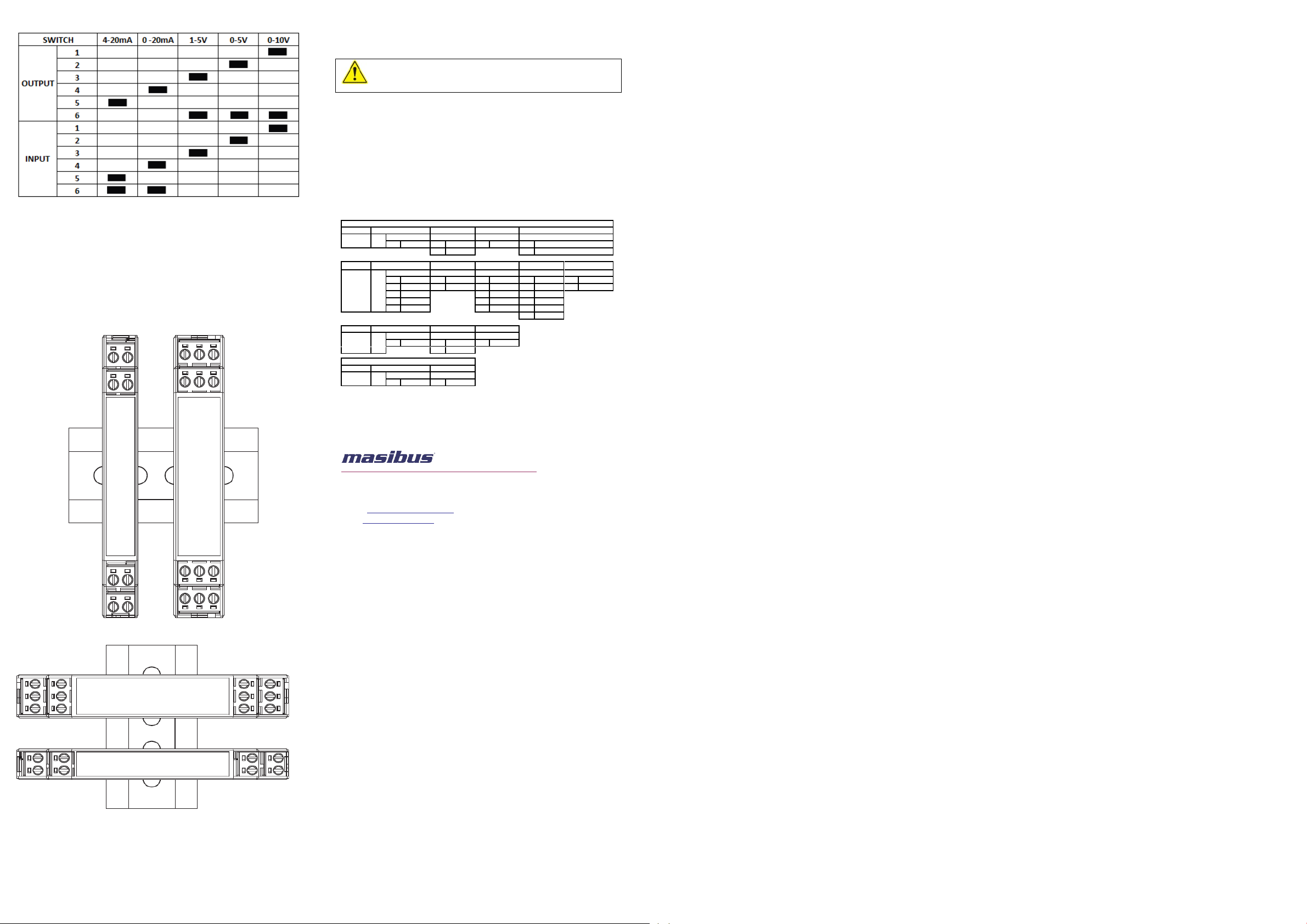
Range of 20V to 265V AC or DC. 9000C model is further enhanced with Switch selectable
I/O configuration for I/O ranges i.e. 0/4-20mA, 0/1-5V and 0-10V. This feature allows user
to have freedom to change 0/4-20mA, 0/1-5V and 0-10V I/O types only, using switch
available on side of device and with minor tuning using front accessible trim-pots,
depending upon field requirements.
9000C (Aux Powered Model) is equipped with Built in transmitter power supply (TPS) that
can drive 2 Wire transmitters in case of 4-20mA DC input signal.
9000C Series isolators act as signal distributor when used with more number of outputs.
9000C Offers excellent accuracy and stability delivering reliable operation in hostile
environments with full 3 port isolation between input, output and power supply.
9000C Series are flexible for DIN rail mounting and easily installable. Its compact design
consumes less space and hence reduces cost of overall installation.
With 9000C 'L' Loop Powered Version, overall wiring can be reduced availing same
performance and overall System power consumption can be reduced.
9000C with HART Pass through (Aux Powered Model) is dedicated Signal Isolator, for 2-
wire HART Programmable devices, with HART Pass capability and all enhanced features of
9000C Series. This model can also provide an additional Output of Current for Non HART
compatible devices.
FEATURES
Available in Aux Powered (AP) and Loop Powered (LP) options
Extended Universal Power Supply Range: 20V to 265V DC or AC along with Safe and
Sufficient Power For Field 2 Wire Transmitter (Aux Powered Model)
Switch Selectable Input/Output option (Aux Powered Model)
Rugged & accurate 4 wire and 2 wire isolator
Up to 2 outputs with Short Circuit Protection (Aux Powered Model)
Wide zero & span adjustment limits
1.5KV AC Isolation between I/P, O/P and Supply
High CMRR and NMRR
High output Load Driving Capability
Lowest Long term Drift
APPLICATION
Field interface device
Transmitter Power Supply
Signal Repeater
Signal Converter
Factory automation
Impedance matching of transmitters and receiver instruments
‘L’ Version: 4-20mA
‘S’ Version: 4-20mA (Standard)
‘M’ Version: 0/4 to 20mA , 0/1 to 5V , 0 to 10V
(DIP switch selection)
‘H’ Version: 4-20mA, HART Pass
Current Input: ≤100 Ω (Loop Powered)
: ≤10 Ω (Aux Powered)
Voltage Input: ≥1 MΩ
‘S’ Version: 4-20mA (Standard)
‘M’ Version: 0/4 to 20mA , 0/1 to 5V , 0 to 10V
(DIP switch selection)
‘H’ Version: 4-20mA, HART Pass on o/p-1,
4-20mA, Standard on o/p-2
Output Load (Loop Powered)
RLoad = [(Loop Supply Voltage –10)/0.021]Ω
Output Load (Aux Powered)
mA: ≤750Ω@20mA (SOP),≤550Ω@20mA (DOP)
V: Load Current ≤ 5 mA
(e.g. for 0-5V: 5V/5mA ≥ 1 KΩ)
Green (Aux Powered, ‘S’ version only)
10 to 36VDC with reverse polarity protection
Power Consumption (Aux
Powered)
Input to Output: Galvanic Isolation of 1.5KVAC
for 1 minute
Power to Input and Output :
Reinforced insulation according to
IEC/EN 61010-1, rated insulation voltage
3KVAC (For CE marked 9000C SOP ‘S’ and
‘M’ Model)
Galvanic Isolation of 3KVAC for 1 minute (For
CE marked and Non-CE Model)
Input to Output :
Functional insulation according to
IEC/EN 61010-1, rated insulation voltage
1.5KVAC (For CE marked 9000C SOP ‘S’ and
‘M’ Model)
Galvanic Isolation of 1.5KVAC for 1 minute
(For CE marked and Non-CE Model)
Output to Output :
Galvanic Isolation of 1.5KVAC for 1 minute
(For Non-CE Model)
12.5(W)x100.2(H)x115.2(D) mm (For SOP Aux
and Loop Powered Model)
17.5(W)x100.2(H)x115.2(D) mm (For DOP and
HART Pass SOP/DOP)
100 gms. Approx for SOP (Aux and Loop
Powered)
130 gms. Approx for DOP
30% to 95% RH(Non-condensing)
UL,CSA standard & CE certified
DIRECTIVE CONFORMITY (Applicable only for CE Marked 9000C SOP Aux
Powered ‘S’ and ‘M’ Model.)
Electromagnetic compatibility
Directive 2014/30/EU
Low voltage Directive
2014/35/EU
NOTICE
The contents of this manual are subject to change without notice as a result of continual
improvements to the instrument’s performance and functions.
Every effort has been made to ensure accuracy in the preparation of this manual. Should
any errors or omissions come to your attention, however, please inform Masibus Sales
office or sales representative. Under no circumstances may the contents of this manual, in
part or in whole, be transcribed or copied without our permission
SAFETY/WARNING PRECAUTIONS
ESD precautions: Before Installing or Operating the Instrument, always make sure to
discharge the static electricity that might be available on your body to prevent any
damages to Instrument.
Caution: Never carry out work when the Power is turned ON, this
is dangerous. This indicates a danger that may result in minor or
moderate injury or only a physical damage if not avoided.
Wiring must be carried out by personnel, who have basic electrical knowledge and
practical experience. To minimize the possibility of fire or shock hazards, do not expose
this instrument to rain or excessive moisture.
Do not use this instrument in areas under hazardous conditions such as excessive shock,
vibration, dirt, moisture, corrosive gases or oil. The ambient temperature of the areas
should not exceed the maximum rating specified.
Instruments suspected of being faulty must be disconnected and removed first and it is
recommended to send Instrument to Masibus Customer Support Division for testing and
repair.
Before start-up, it is particularly important to ensure:
Terminal wiring: check that all cables are connected correctly and are according to the
connection diagram.
All wiring must confirm to appropriate standards of good practice and local codes and
regulations. Wiring must be suitable for voltage, current and temperature rating of the
system. Beware not to over-tighten the terminal screws.
Unused terminals should not be used as jumper points as they may be internally
connected, which may cause damage to the unit.
After installation the terminal area must be covered to provide sufficient protection against
unauthorized Access to live parts. This is ensured by installing the device in the control
Cabinet or distributor box.
WARRANTY
Warranty does not apply to defects resulting from action of the user such as misuse,
improper wiring, operation outside of specification, improper maintenance or repair, or
unauthorized modification.
Masibus is not liable for special, indirect or consequential damages or for loss of profit or
for expenses sustained as a result of a device malfunction, incorrect application or
adjustment.
Masibus total liability is limited to repair or replacement of the product. The warranty set
forth above is inclusive and no other warranty, whether written or oral, is expressed or
implied.
OVERALL DIMENSIONS (In mm)
9000C SOP (Loop Powered and Aux Powered)
9000C DOP, HART Pass SOP and HART Pass DOP (Aux Powered)
CONNECTION DETAILS
Block Diagram and Connection Details of Loop Powered Device
Block Diagram and Connection Details of SOP (Aux Powered)
Block Diagram and Connection Details of DOP (Aux Powered)
Block Diagram Connection Details SOP HART Pass Suitable for 2 wire
transmitter only (Aux Powered)
Block Diagram and connection details of DOP HART Pass Suitable for 2 wire
transmitter only (Aux Powered).