Masport Petrol Chipper Shredder User manual

Please read these instructions carefully
before assembly.
Keep the instructions in a safe place for
future use.
Owner’s
Manual
Chipper Shredder.
www.masport.com
536128

ENGLISH

For your future records, please complete the table below:
Serial No. ________________ Retailer ______________________ Purchase Date ____/____/____.
Index: Topic Page Topic Page
Initial Assembly 3 Basic Maintenance Information 6
Operating Instructions Detailed Maintenance Information
Transporting 3 Removing Shredder Blades 7
Preparation, Starting 4 Engine Removal, Rotor Removal 8
Chipping 5 Belt Replacement 8
Shredding 5 Warning Decals 9
Additional Safety Information
Training 6
Operation 6
Maintenance & Storage 6

3
1. The separate items you should have in the
two cartons are:-
Carton 1
•Engine – Chassis assembly
•A Fuel Tank
•Two L-shaped legs
•Two Wheels
•A Plastic Bag containing
-an Operation and Maintenance
Manual
-an Engine Booklet
-2 off M8 x 20 screws
-2 off 16mm Axle Washers
-2 off Chute Retainers
-6 off 8mm x 16mm Washers
-6 off 8mm Nyloc Nuts
-2 off 8mm Spring Washers
-2 off Axle Circlips
-4 off 30mm Bolts for Chute Handle
Carton 2
•A plastic chute with rubber flap and metal
plate attached
A Chute handle
Carton 3
•A Chipper chute with clamp
1. Place a block of wood roughly 95 x 95 x 300
under the front of the discharge chute (see fig.
1)
2. Bolt the two front legs in position. Note that
the legs are right and left-handed. The leg
mounting holes are off centre and should be
toward the rear of the machine.
3. Place the block of wood under the rear of the
machine, near the back axle.
4. Put the wheels on the axles. There should be
an axle washer on the outside only of the two
wheels. Then put the two axle clips on the
ends of the axle.
5. Lift the engine and remove the wooden
packer that is under the engine mounting
plate.
6. Attach the handle to the shredder chute.
7. Attach the shredder chute to the chassis using
two 8mm x 20mm screws and two chute
retainers, with plain washers and spring
washers on the screws at the front and with
two Nyloc nuts outside the chute at the sides.
See Fig. 2.
8. Attach the Chipper Chute to the Chipper Tube
and tighten the clamp. ( The machine will not
start without the Chipper Chute attached. )
9. Add oil and fuel to the engine (see engine
booklet).
1. To move the unit, place a foot behind a wheel
and tilt the unit backwards until it passes its
balance point.
DANGER: NEVER MOVE THE UNIT WHILE
THE ENGINE IS RUNNING.
2. When crossing rough terrain or sloping areas,
hold the handle firmly at each side with both
hands (to prevent tipping). In some instances
it may be easier to walk backwards, towing
the unit.
3. With the chute removed, the unit will fit in
some larger station wagons, but it must be
tied in position if left upright. Once the engine
is filled with oil, it cannot be tipped on its side
unless the oil is drained out.

4
Washer & Nut
for this bolt on
insideof chute.
M8 X 20 Screws
+springwashers
+plainwashers
Shredder chute
Chipper chute
Belt Guard
Axleclip
+washer
Front legs
Bolt head
Fig.2
1. Obtain and wear safety glasses at all times
while operating the machine. Hearing
protection is also recommended, especially
for extended operating periods.
2. Avoid wearing any loose fitting clothing.
3. Before starting the machine, check that all
screws, nuts, bolts and other fasteners are
properly secured. Replace damaged or
unreadable warning and operating decals.
4. Use extra care in handling gasoline and other
fuels. They are flammable and the vapours
are explosive.
a) Use only an approved container for fuel.
b) Never remove fuel cap or add fuel with
engine running. Allow engine to cool
before refueling. Do not smoke.
c) Never refuel the machine indoors.
d) Never store the machine or fuel container
inside where there is an open flame such
as a water heater
1. Ensure the Chipper Shredder is on stable
level ground so it won’t tip over. Do not
operate the machine on a hard surface such
as concrete, as discharged material will
rebound and may damage people or property.
2. Before starting the engine, check that the
engine mounting plate is roughly horizontal. If
not – see maintenance instructions.
3. Turn switch on side of engine to “ON”
position.
4. Push choke lever to (choke)
position and throttle lever to fast position.
5. Pull the starting cord until the engine starts.
Push the choke lever to (Run)

5
position.
6. Adjust the throttle to achieve the desired
operating speed.
7. Once the engine is hot, it is not necessary to
use the choke when restarting.
8. Do not restart the unit with material in the
chipper tube or shredder chute. The additional
drag may cause severe wear on the drive belt
or you may damage the pull starter on the
engine.
IMPORTANT: NEVER PUT YOUR HANDS OR
FINGERS IN THE CHIPPER TUBE. FOR THE
PROTECTION OF OTHERS, DO NOT LEAVE
THE MACHINE UNATTENDED WHEN IT IS
RUNNING. THE M/C WILL NOT OPERATE
WITHOUT THE CHIPPER CHUTE ATTACHED.
1. Branches up to 65mm diameter can be
chipped using the chipper tube on the right
side of the unit. Green timber will chip much
faster than dry timber. Do not chip wood that
contains nails.
2. If the unit cannot be placed on the surface on
which the chips will be spread, then a sheet of
plastic or canvas can be laid under the
machine to collect the chips.
NOTE: DO NOT MOVE THE UNIT WITH THE
ENGINE RUNNING. THE RESULTANT
TILTING MAY STARVE THE ENGINE OF OIL
AND CAUSE IT TO SEIZE.
3. If the engine is slowing substantially while
chipping, reduce the rate you are feeding
branches into the machine. This will also
make the resultant chips smaller and will
extend the life of the drive.
Alternatively, check if the blade is blunt.
NOTE: DO NOT throw the end of branches
that are larger than 15mm diameter into the
shredder chute. Push them down the chipper
tube using another piece of wood.
4. Rotating the branches as you chip can reduce
the incidence of bark wrapping around the
shaft and causing jamming.
5. Branches with multiple smaller branches
connected can be fed into the chipper tube
until you are left with a handful of small leaves
and branches. This handful can then be
dropped into the shredder chute.
6. If the chipper becomes jammed, the engine
should be stopped immediately (if it has not
stalled). Remove the offending material before
restarting. This may involve lowering the
shredder mesh, turning the shredder
assembly backwards (with the spark plug
disconnected) and prising the material out of
the tube with a long knife, screwdriver etc.
NOTE: DO NOT continue chipping if the drive
belt is slipping or smoking. To readjust the
belt, see maintenance information.
NEVER operate the machine with the small
maintenance cover plate in its open position
or removed. Serious injury would result if
someone put their finger into the hole which is
under the cover plate.
DANGER:
A. DO NOT PUSH MATERIAL INTO
THE SHREDDER CHUTE WITH
YOUR HANDS. USE A GREEN
BRANCH OR A PIECE OF
SOFTWOOD.
B. WEAR EYE PROTECTION.
1. Many organic materials as well as leaves and
branches can be shredded. Vines will need to
be cut into short lengths (about 300mm)
before feeding them into the shredder chute
as they may wrap around the shaft. This could
cause jamming of the unit and cause severe
injury to the operator.
IMPORTANT: DO NOT ATTEMPT TO
SHRED OBJECTS SUCH AS GLASS,
METAL, PLASTIC BOTTLES OR ROCKS.
2. Preferably wear gloves when feeding small
branches into the shredder chute, hold the
branches loosely and release them long
before they contact the rotating blades.
BEWARE OF A SUDDEN JERK AS THE
BRANCHES ARE TUGGED INTO THE
SHREDDER.
3. Branches over 15mm diameter will rattle
around inside the shredder for some time and
may damage the shredding screen. These
branches should be fed into the chipper tube
instead.
4. Leaves shred very well, especially if they don’t
contain long sticks and they are kept loosely
stacked in the shredder chute, i.e. don’t force
them down the chute if it becomes clogged.
Stop the engine and free the jam.
5. Keep watching the area under the machine to
ensure that the shredded material has not
built up to the point where further shredded
material cannot escape. This may prevent
proper discharge and could cause kickback of
material through the feed opening. Move the
machine backwards a short distance as
material builds up underneath.
6. Control the rate of feeding material into the
shredder chute so that the motor is not
overloaded. In particular, try to avoid rapid
changes in engine speed caused by
instantaneous bulk feeding.
DANGER: NEVER PUT YOUR HANDS OR FEET
UNDER THE MACHINE WHEN IT IS RUNNING.

6
7. If the shredder screen becomes clogged, stop
the engine and pull the R clip from the pin that
protrudes under the belt guard near the front
support. Using the T grip below the chipper
tube, pull the pin out of the shredder screen.
Generally, this will cause the screen to open
downwards. If it is jammed, it can be gently
prised down using the shredder rod or a large
screwdriver.
DANGER: DO NOT ROTATE THE
SHREDDER ASSEMBLY WITHOUT FIRST
DISCONNECTING THE SPARK PLUG LEAD
FROM THE SPARK PLUG.
8. Once a jam is cleared, push the screen into
place and replace the pin. Note that the T grip
must be horizontal for the pin to go fully
through the screen. Replace the R clip.
9. If the screen is blocking repeatedly when
shredding material such as wet leaves, try
mixing some dry material with the wet material
to scour the screen clear or use the (optional
extra) bar grate. See below.
10. After shredding “stringy” material such as
palm leaves, remove the shredder chute and
check that they have not wrapped tightly
around the ends of the rotor, inside the
chamber. If so, carefully remove them with a
flat screwdriver. Some varieties of palm
leaves can be cut in the chipper tube.
NOTE: If material that is wrapped around the
shaft is not removed, the shaft becomes hot
and “boils” the oil out of the shaft bearings.
The bearings will then fail.
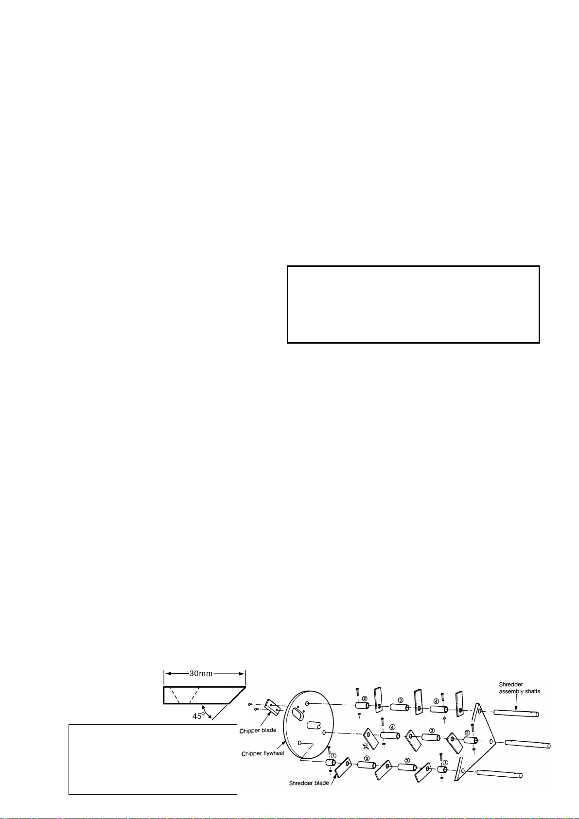
11. USE OF (OPTIONAL EXTRA) BAR GRATE.
For shredding soft, bulky or wet material such
as weeds or vegetable matter, an optional bar
grate can be purchased. To fit the bar grate,
turn the engine off, remove the spark plug
lead and the belt guard. Pull out both R clips
securing the shredder mesh rods, remove the
rods and the mesh. Insert the bar grate from
below and insert the rods through the grate.
Reconnect the R clips, the belt guard and the
spark plug lead.
1. TRAINING
1.1 Become familiar with the owner’s manual
before attempting to operate this equipment.
1.2 Do not allow children to operate this
equipment.
1.3 Do not operate the equipment in the vicinity of
bystanders.
1.4 Carbon monoxide can be extremely
dangerous in enclosed areas; do not run the
machine in an enclosed area since the
exhaust from the engine contains carbon
monoxide, which is colourless, odourless and
tasteless.
1.5 Do not place hands or any other part of the
body or clothing inside the feeding chutes,
discharge area, or near any moving part.
1.6 Before inspecting or servicing any part of the
machine, shut off the power source,
disconnect the spark plug wire from the spark
plug, and make sure that all moving parts
have come to a complete stop.
2. OPERATION
2.1 When feeding shreddable material into the
equipment, be extremely careful that pieces of
metal, rocks, bottles, cans or other foreign
objects are not included.
2.2 If the cutting mechanism strikes any foreign
objects or if the machine should start making
any unusual noise or vibration, immediately
shut off the engine and allow the machine to
stop. Disconnect the spark plug and take the
following steps:
1) Inspect for damage
2) Replace or repair any damaged parts
3) Check for and tighten any loose parts.
Do not attempt to repair the machine unless
you are competent to do so.
2.3 Keep the engine clean of debris and other
accumulations to prevent damage to the
engine or possible fire.
2.4 Keep all guards and deflectors in place and in
good working condition.
2.5 Always stand clear of the discharge area
when operating this machine.
2.6 Keep you face and body away from the
discharge opening.
2.7 Do not overreach. Keep proper balance and
footing at all times.
2.8 Do not tamper with the engine governor
settings on the machine: the governor controls
the maximum safe operating speed and
protects the engine and all moving parts from
damage caused by overspeed. Seek
authorised service if a problem exists.
3. MAINTENANCE AND STORAGE
3.1 When this equipment is stopped for servicing,
inspection, or storage, or to change an
accessory, make sure the spark plug wire is
disconnected from the spark plug. Allow the
machine to cool before making any
inspections, adjustments etc. Maintain the
machine with care and keep it clean.
3.2 Store the machine out of reach of children
and where gasoline vapour will not reach an
open flame or spark. For extended storage
periods, run the unit dry of petrol. Always
allow the machine to cool before storing.
a) Two 13mm ring open-ended spanners.
b) 5mm allen key.
c) Shifting spanner 10”.
1. Every 5-10 hours of operation check the oil
level and top up if necessary. Change the oil
in accordance with the instructions in the
engine booklet.

7
2. Regularly check the condition of the engine air
cleaner, especially in dusty environments.
3. The drive belt may stretch after a short period
of use, but should then stabilise for a
considerable time if not overloaded or
constantly slipped.
If the engine is not approximately level (i.e. if it
is hanging backwards away from the chute)
then the spring pressure on the belt may be
reduced causing the belt to slip.
To return the engine to level: Remove the
belt guard; loosen the 4 engine mounting bolts
using two 13mm spanners; raise the engine
mounting plate until the engine is tilting
slightly forward; pull the engine back in its
mounting slots and tighten two rear engine
mounting bolts; check that the engine is now
level; tighten the remaining engine bolts;
replace the belt guard.
NOTE: Replace the drive belt when the
engine has reached the end of its slotted
holes and it is still sloping backwards.
4. If the engine is vibrating badly, the 10mm
engine pivot bolts under the engine mounting
plate may need tightening. Do not tighten
them fully, and after tightening check that the
engine still pivots by lifting it by hand. If it does
not pivot, the belt will slip as the weight of the
engine keeps the belt tight. Removing the
pivot bolts and greasing them at least once a
year will increase the life of the pivot bushes.
New Nyloc nuts may be necessary after
removing them a few times.
5. To remove the chipper blade for
sharpening/replacement.
•Disconnect the spark plug lead from the
spark plug.
•Loosen the upper bolt on the
maintenance cover plate and remove the
lower bolt.
•Remove the plastic shredder chute.
•Rotate the maintenance cover plate to
expose the hole under the plate.
•Rotate the shredder-chipper rotor until
the chipper blade is opposite the
maintenance hole.
•With a sharp object such as a nail,
remove wooden debris from the allen key
holes in the two countersunk chipper
blade bolts.
•Remove the bolts and the chipper blade
using an allen key and a 13mm spanner.
[BEWARE OF THE SHARP EDGE ON
THE CHIPPER BLADE.]
•Sharpen blade to 45o. Do not remove
more than 2mm of material as this will
cause rotor imbalance. I.e. the minimum
blade dimensions are:
•Never use a cracked chipper blade.
•Use new Nyloc nuts when replacing the
chipper blade, and new bolts if they
appear damaged. Ensure the blade is
sitting flat on the rotor surface before
tightening.
!
a) 4mm Allen key.
b) 8mm spanner.
c) ¼” rod or a Phillips head screwdriver with
a shaft 6mm diameter or smaller.
d) Bearing puller.
e) Two 18mm open ended spanners.
f) 1/8” Allen key.
"
1. The shredder blades can be turned 180oto
expose fresh cutting faces.
2. To remove the blades, first remove the
shredder chute and open the maintenance
cover near the chipper tube.
3. Remove the spark plug lead from the spark
plug.
4. Remove the belt guard.
5. Align one shredder assembly shaft with the
hole under the maintenance cover.
6. Remove the small bolts through the shredder
shaft.
7. Insert a rod or Phillips head screwdriver
through the small hole above the pulley in the
left hand plate and push the shredder shaft
out through the maintenance hole.
8. Check the condition of the shredder shaft. If it
is badly grooved (i.e. grooves greater than
1mm deep) then replace it. Similarly replace
worn spacers (see lengths below.)
9. Repeat the same operation for the other two
shredder shafts.
10. When replacing the shafts and blades, use
new Nyloc nuts on the shaft bolts and install
new bolts if they are damaged or worn. Do not
reuse cracked or badly worn blades.
11. The blades must be installed as shown above.
Of particular importance, the blade X must be
opposite the chipper blade or it will hit the
chipper blade bolts when it rotates on its own
shaft.
IMPORTANT:
CHECK THE ROTOR ASSEMBLY FOR LOOSE BOLTS &
CRACKED, WORN OR BENT PARTS AFTER EVERY 20
HOURS OF USE OR AFTER IMPACT WITH A FOREIGN
OBJECT.
REPLACE WORN OR DAMAGED PARTS.
SPACER
No. LENGTH
(mm) PART
No.
No. PER
1 18 536043 2
2 36 536042 2
3 51 536045 4
4 51 536044 2

8
#"
Disconnect the engine from the unit by removing
the belt guard, the drive belt, the belt tensioning
spring, and the two engine pivot bolts.
"
1. Remove the 3½” pulley from the rotor
assembly by first removing the circlip, then
loosening the boss screw and withdrawing the
pulley using a puller. Penetrene injected
through the boss screw hole may assist
removal.
2. Remove the shredder chute.
3. Remove the 13mm screw from the end of the
rotor shaft adjacent to the chipper tube.
4. Take the four nuts from the bearing screws.
5. Loosen all four bearing boss screws using a
1/8” Allen key.
6. With a brass (or similar) drift, drive the
shredder shaft partially through the bearing on
the chipper tube side of the machine.
7. Remove the bearing on the pulley side of the
machine using a puller.
8. Remove the chipper blade or ensure that the
blade is nowhere near the chipper tube.
9. Tap the rotor shaft from the pulley side using
a soft hammer. Be careful not to damage the
chipper blade.
10. Remove the bearing on the chipper tube side
of the machine using a puller.
11. The rotor assembly can now be removed by
disconnecting one of the side plates from the
machine.
NOTE: When reassembling, put Loctite 262
(or similar) on the pulley boss screw and
always ensure that a good circlip is fitted.
1. Remove the belt guard.
2. Disconnect the spark plug lead from the spark
plug.
3. Loosen the four engine mounting bolts and
slide the engine forward.
4. Raise the engine and remove the belt.
5. When a new belt is installed, readjust the
engine position so that it is level when the belt
is tight.
6. Attach the belt guard.
Micro-Switch Adjustment
If the m/c will not start check that the chipper
chute is depressing the micro-switch roller in
the following way: (See Figs. 3 & 3A.)
1. Remove nuts 1& 2 and the spring washers
and remove cover.
2. Loosen the chipper chute and slide it up the
chipper tube. Then slide it back down the
chipper tube. An audible ‘click’ should be
heard as the chipper tube depresses the
micro-switch roller if the micro-switch is
functioning correctly.
3. If no ‘click’ is heard clamp the chipper chute in
its operating position, under the micro-switch
roller, and loosen nuts 3 & 4.
4. Move the micro-switch closer to the chipper
tube until it 'clicks' then re-tighten the nuts 3 &
4.
5. To check that the micro-switch is now set
correctly loosen the chipper chute clamp and
slide the chipper chute up and down the
chipper tube listening for the ‘click’ as it
depresses the micro-switch roller.
6. Repeat steps 3 to 5 if necessary.
7. When satisfied that the micro-switch is
working correctly replace cover, washers &
nuts.
NUT 4
NUT 3
NUT 1
NUT 2
SPRING
WASHER
COVER MICRO SWITCH
MICRO SWITCH
ROLLER
CHIPPER TUBE
Fig. 3
NUT 4
NUT 3
NUT 1
COVER
Fig.3A

9
$!!% #&
$!!% #&$!!% #&
$!!% #&
Masport Chipper shredders are manufactured in New Zealand by
MASPORT LTD.1/37 MT WELLINGTON HIGHWAY.
P.O. Box 14-349 Panmure, Auckland New Zealand
Revised Sept 2004

Español

IMPORTANTE:Guardeestemanualdeinstruccionesjuntoalmanualdelmotorenun
lugarseguroparatenerunareferenciadeusoenelfuturo.
EstemanualcontieneinformaciónacercadelaBiotrituradoraMasport.
Paraunainformaciónenelfuturo,porfavorrellenelatablasiguiente:
NºSerie:
Revendedor:
Fechadecompra:
INDICEPAGINA
MONTAJEINICIAL3
TRANSPORTE3
PREPARACIÓNPARAARRANQUE4
TRITURARTRONCOS5
TRITURARRAMAS5
PREPARACIÓN6
ARRANQUE6
MANTENIMIENTOYALMACENAJE6
MANTENIMIENTOBASICO6
SUSTITUCIÓNDECUCHILLAS7
AJUSTEMOTOR8
SUSTITUCIÓNCORREA8
SEÑALESADVERTENCIA9

MATERIALINICIAL
1. Laspiezasquedebeposeerenlastrescajasson:
Caja1:
•Maquinaconmotor.
•2patassujeciónformadeL
•2Ruedas
•1Bolsadeplásticoquecontiene:
‐Manualdeusuario
‐2tornillosM8X20
‐2Arandelas16mm
‐2sujecionesparatolva
‐6Arandelas8x16mm
‐6Tuercasnylon8mm
‐2Sejerde8mm
‐2pasadores
‐4tornillos30mmparalasasas.
Caja2
‐Tolvadeplásticopararamasconsugoma.
‐Asas
Caja3
‐Tolvaparatroncosconsuabrazadera.
MONTAJE
1. Prepareuntrozodetroncode95x95x300,yposiciónelodebajodelasalida
dedescarga.VerFig.1
2. PongalasdospatasenformadeLenposicióncorrectajuntoconsus
correspondientetornillosyapriete.
3. Sitúeeltroncoenlaotrapartedelamáquina(partemotor).
4. Coloquelasdosruedaseneleje,coloquelasarandelasyfinalmentecoloque
lospasadores.

TOLVAPARARAMAS
ASAS
BUJIA
Mantenimiento
sensor
CUERDA
ARRANQUETubotriturado
troncos
PARTEDELANTERA
PARTETRASERA
PATAS
DELANTERAS
Situeuntroncoo
medracuando
vayaaponerlas
patas.
SALIDAPOSTERIOR
RAMAS
5. Quiteeltroncodelamaquina.
6. Coloqueyfijelasasassobrelatolvaderamas.
7. Ensamblarlatolvaderamassobrelamaquinausandolosdostornillos8x20
mmylasdossujecionesparatolva,coloquelostornillosconlaarandelaplana
pordentrodelatolvaylastuercasdefrenoalaparteexterior.VerFig.2
8. Ensamblelatolvadetroncossobrelasalidacirculardelamaquinayajustela
abrazadera.(Nota:lamaquinanoarrancarasinoconectaestatolva).
9. Añadaaceitealmotorsegúnmanualdelmotor.

TRANSPORTE
1. Paradesplazarlamáquinadeunsitioaotro,inclinelamaquinahaciausted,
deslizándolasobrelasruedas.
PELIGRO:NUNCADESPLACELAMAQUINACONELMOTOREN
FUNCIONAMIENTO.
2. Enterrenosdifíciles,mantengafirmementeagarradaslasasasdelamaquina,
paranovolcarla.
3. Recuerderellenarprimeroelcárterdeaceitedelmotor,yluegoposicionarla
tolvadetroncos.

ARANDELA+TUERCA,ENEL
INTERIORELTORNILLO
TOLVATRONCOS
TOLVARAMAS
TORNILLOS8X20
+SEGER
+ARANDELASPLANAS
PROTECTORCORREA
ARANDELA+PASADOR
PATASDELANTERAS
PREPARACIÓN
1. Equípeseconropaprotectoradeseguridad,gafasdeprotecciónyprotectores
acústicos.
2. Evitecolocarsecualquierropaquelepuedasermuyfatigosa.
3. Asegúreseantesdearrancarlamáquinadequelostornillos,tuercas,yotros
componentesesténbienajustadosyapretados.Sustituyacualquierpiezaque
observedefectuosaodañadaantesdelapuestaenmarcha.
4. Mantengaespecialatenciónconloscombustiblesysusgases,yaqueestosson
especialmenteexplosivos.
‐Utilicesoloelcombustiblepararellenareldepósitodecombustibledel
motor.
‐Nuncaabraeltapóndegasolinaoañadagasolinacuandolamaquina
esteenfuncionamiento.
‐Nuncaañadagasolinadentrodecualquierlugarcerrado.

‐Nuncarellenedegasolinalamaquinasiseencuentrasituadocercade
cualquierllama.
ARRANQUE
1. Asegúresedequelamaquinaseencuentrasobreunterrenollanoysin
irregularidades,yaquepodríaninfluirenelfuncionamientodelamaquina.
2. Antesdelarranqueasegúresedequeelmotorseencuentramontado
correctamente,ysituadoestrictamenteenposiciónhorizontal.
3. GireelcontactodelmotoralaposiciónONyabraelgrifodegasolina.
4. Coloquelapalancadelaireparaarrancarenfrio,hacialaposiciónizquierda,y
acelereelmotor.
5. Tiredelacuerdadearranque,yunavezenmarchavuelvalapalancadelaire
hacialaposiciónderecha.
6. Ajustelaaceleracióndelmotorsegúnlavelocidaddetrabajodeseada.
7. Unavezelmotorestacaliente,noesnecesariovolveracolocarlapalancadel
aireparaarrancarelmotor.
8. Noarrancarnuncaelmotorcontroncosoramasenelinteriordelatolvas,ya
queestospuedendañarseriamentelamaquinaysufuncionamiento.
TRITURADODETRONCOS
IMPORTANTE:NUNCAPONGASUSMANOSODEDOSENLATOLVAPARATRONCOS,
YPARAPROTENCCIÓNDEOTROS,NODEJENUNCALAMAQUINADESATENDIDA
CUANDOESTETRABAJANDO.LAMAQUINANUNCAARRANCARÁSINOESTA
SITUADALATOLVAPARATRONCOS.
1. Podrántriturarsetroncosconundiámetromáximode65mm,lostroncosde
menordiámetrosetrituraranmasfácilmente.Nuncatritureningunaramaque
puedaconteneralgúnclavootrozometálico.
2. Nointentequitarlasastillasquesalendelamaquinaporlaparteinferior
mientraslamaquinaesteenfuncionamiento,yaquecualquierrestoquepueda
quedarlepodríadañar.
NOTA:NOMUEVALAMAQUINACUANDOELMOTORESTEEN
FUNCIONAMIENTO,YAQUEELACEITEDELMOTORPUEDEDESPLAZARSEY
DAÑARELMOTOR.
3. Paraunbuenfuncionamientoydurabilidadserecomiendamantenerelmotora
lasrevolucionesmedias,eintroducirlostroncoslentamenteYaque
conseguiremosunasastillasmuchamaspequeñasyunamayordurabilidadde
lascuchillas.
NOTA:Nointroduzcaenlatolvadelasramas,ramasquesuperenlos15mmde
diámetro,utilícelassiempreenlatolvadelostroncos.

4. Serecomiendaunalimpiezadelasramasquevanadheridasalostroncospara
unfuncionamientomasoptimomientrastrituramostroncos.
5. Estaspequeñasramassecundariaspodemostriturarlasenlatolvadelasramas.
6. Encasodequeobservealgúntipodeanomalíaoruido,debedetener
rápidamenteelfuncionamientodelmotor,yseguidamentecomprobarquela
cribanoestaobstruida,quelascuchillasestánafiladascorrectamente,yqueno
existeningunapiezadañada.
NOTA:Nosigaempleandolamáquinasilacorreapatina,haceruido,humo,ose
estaquemando.Reajustelacorreainmediatamente,veainformaciónsobre
mantenimiento.
NUNCAutilicelamaquinaconelinterruptordelatolvadetroncosdesconectado.
Podríanocurrirdañosmuypeligrososendedosomanos.
TRITURADODERAMAS
PELIGRO:
A‐Nuncapongasusmanosdentrodelatolvadelasramas,utiliceotrasramaso
arbustos.
B‐Utilicesiempreprotecciónvisualogafas.
1. Materialesorgánicosasícomoramaspuedensertrituradasconlatrituradora.
Vidoparrasserecomiendaquenosuperenlos300mmdelongitud,yaque
estospodríanenrollarseenelejeydañarlamanodeloperario.
IMPORTANTE:NUNCAINTENTETRITURARMATERIALESCOMOVIDRIO,
METAL,BOTELLASDEPLÁSTICOOPIEDRAS.
2. Serecomiendaelusodeguantesdeproteccióncuandovayaatriturarramas.
TENGAESPECIALATENCIÓNENNOINTRODUCIRNUNCATRONCOSENLA
TOLVADERAMAS.
3. Eldiámetromáximodetrituradoparalasramasesde15mm.
4. Dejequelasramassetriturencorrectamenteysalganporlasalidaposterior,en
casodenotaralgúnruidooanomalíadetengainmediatamentelamquinay
limpielacriba.
5. Controlequelasalidaposteriordelamaquinadispongadeespaciosuficiente
parasufuncionamiento,encasodequeexistabastantematerialtriturado,
desplacelamaquinadesitio.
6. Intentecontrolarelfuncionamientodelmotorcorrectamente,evitelos
altibajosmediantesobrecargasdematerial.

PELIGRO:Nuncapongasusmanosenlaparteposteriordelamaquina
mientrasesteenfuncionamientoyaquepodríadañarle.
7. Encasodequeeltambordecuchillasllegueaembozarsederamas,pareel
motor,saqueelpasadorenformadeRyelbulón,quitelasramasque
obstruyen,siempreprotegidoconloscorrespondientesguantesenlasmanos,y
vuelvaamontardenuevoelpasador.
8. Encasodequelasramasseobstruyanrepetidamente,seaconsejadejarlas
ramasverdesquesesequenparaunmejortriturado.
9. Encasodetrituradodematerial“fibroso”comohojadepalmeraohojade
olivo,serecomiendafijarsebienquenoseobstruyaeneltambornicriba,en
casodesucederesto,sustituirlacribaporlacribaespecialparaestetipode
material.Tambiénpuedeutilizarselatolvaparatroncos.
NOTA:Encasodenolimpiarelejedeltambor,estepuedecalentarseyhacer
quelosrodamientospierdansuaceiteygrasa,finalizandoconunaroturadelos
mismos.
10. USODELACRIBAESPECIAL
Paratriturarmaterialeshúmedos,mojados,voluminosos,tiernosofibrosos,
existeunacribaespeciallacualnosproporcionaraunmejorfuncionamiento.
ParalasustitucióndeestadebequitarelpasadorenformadeR,quitareleje
deamboslados,ysustituirlacribaenlamismaposiciónquequitolaantigua.
SEGURIDADADICIONAL
1. PREPARACIÓN
1.1. Familiaríceseconelmanualantesdeempezaratrabajar.
1.2. Nopermitaquelosniñostrabajenconesteequipo.
1.3. Notrabajecercadeningunapersonaalrededor.
1.4. MonoxidodeCarbonoexpulsadoporlamaquinapuedeser
extremadamentepeligrosoenáreascerradas,Nuncaarranquelamaquina
enáreascerradas.
1.5. Nuncapongamanosocualquierotrapartedelcuerpocercadeninguna
cuchilla,áreadedescargaocualquierpiezaquetengamovimiento.
1.6. Antesdeinspeccionarcualquierparteinteriordelamaquina,asegurese
dequetodasloaspartesdelfuncionamientoesténtotalmenteparadas.
2. PUESTAENMARCHA
2.1. Cuandoañadamaterialenlatolvaderamas,tengaespecialatención
porsiexistealgunapiezademetal,roca,botellas,ocualquierotromaterial
quenodeberíaponer.
2.2. Sielsistemadefuncionamientogolpeaohacecualquierruidoinusualo
vibración,pareinmediatamenteelmotor,yacontinuación:
a) Inspeccionesiexistealgúndaño.
b) Cambieoreparecualquierpiezadañadaorota.

c) Asegúresedenofalteningunapieza.
Nointenterepararlamaquinaencasodequenoestecapacitadoparaello,
llévelaalserviciopostventadondecomprolamaquina.
2.3. MANTENGALIMPIOELMOTORDEESCOMBROSPARAEVITAR
CUALQUIERFUEGO.
2.4. Mantengatodaslaspartesdelamaquinaenunlugarseguroparaque
nosedañen.
2.5. Siempremantengaeláreadedescargalibreparaunbuen
funcionamiento.
2.6. Manténgasesiemprefueradeláreadedescargaparaevitardañosen
caraypartesdelcuerpo.
2.7. Noestedemasiadotiempocercadelamaquinaymantengauna
distanciaprudencial.
2.8. Nointenteniaceleresiemprealmáximolamaquinayaqueestapodría
sufrirunsobreexcesoyposibleroturasenelfuturo.
3. MANTENIMIENTOYALMACENAJE
3.1. Encasodequevayaaalmacenarla,repararla,oinspeccionarla,
asegúresesiempredequeelmotorseencuentretotalmentefrio.
3.2. Almacenelamaquinafueradelalcancedelosniños,asegúresedequeel
depósitodecombustibleestevacío,yquelamaquinaseencuentrafuera
delalcancedecualquierllama.
MANTENIMIENTOBASICO
LLAVESREQUERIDAS
a) 2llavesde13planas.
b) Llaveallen5mm
c) 1llavede10mm
1. De5‐10hdeusocompruebeelniveldeaceiteyrelléneloencasodeser
necesario.Cambieelaceitedeacuerdoalmanualdeinstruccionesdel
motor.
2. Regularmentereviselascondicionesdelfiltrodeaire,especialmenteen
lugarespolvorosos.
3. Lacorreadetransmisióndeberáquedarseelásticayacopladaenuncorto
periododetiempo,siemprequenosehayasobrecargadoel
funcionamientodelamaquina.
Encasodequeelmotornoestesituadocorrectamente,puedeocasionar
quelacorreapatineoqueserompaalestardemasiadotensada.
Moverelmotorasusitio:Quitelacorreadetransmisión,aflojeloscuatro
tornillosdelmotor,sitúeelmotorcorrectamentedeformaqueelmuelle
delmotoractúecorrectamente,yvuelvaaapretarlostornillos.
Table of contents
Languages: