© MASS ELECTRONICS Pty Ltd 2008
Page 3
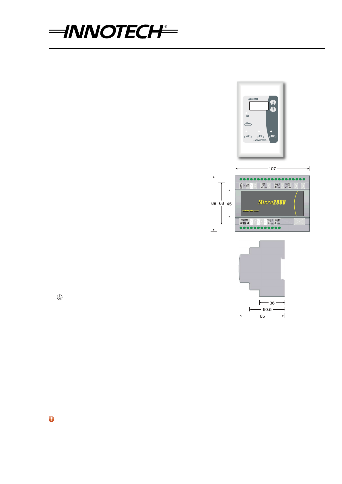
DS 9.03 - M2K03 - Micro2000 Controller
August 2013
Aer Hours Run Time
To view the accumulative Aer Hours Run Time, press and hold
the and buttons for 5 seconds. The displayed
value is the total aer hours run time up to the previous hour. A
total of 9999 hours may be accumulated.
To reset the Aer Hours Run Timer, simply press and hold the
and buttons until the display reverts to 00.
To exit the Aer Hours Mode, press and hold the
button for 5 seconds again. The display will revert back to the
default display.
Start Up Default Settings
The Micro2000 can be set to start in certain modes of operation.
To set the start up defaults, adjust the controller to the desired
settings and then press and hold the and buttons for
5 seconds. When the screen becomes blank, release the buttons
and the new Start Up Defaults will be saved.
Weekly And Holiday Schedules
1. Weekly Schedules:
The Weekly Schedules allows the user to enter up to
two On/ O schedules per day. For example if a
schedule was added for Day 1 (Monday) from 7:30 to 17:30,
the controller would turn on at 7:30 and turn o at 17:30 on
every Monday.
2. Holidays:
The Holiday Schedules allows the user to enter up to 20
Holidays schedules. When a Holiday schedule is active it
will override the weekly schedules and force the controller
o. For example: if a holiday schedule was added for the
23/04 to 25/04, the controller would turn o at midnight on
the morning of the 23/04 and stay o until midnight on the
evening of the 25/04. For a single day holiday, set the On
and O dates to the same value.
Programming Schedules / Clock
The function of the buttons while in programming mode is
shown below.
Enter Back
Delete Copy
1. To enter the CLOCK / SCHEDULE programming mode,
press and hold the Button for 5 seconds. When the
screen becomes blank, stop holding down the button.
2. When you have entered the programming mode, "_CLO"
will be displayed.
Use the and buttons to select either:
"_CLO" Clock "_
SCH"
Weekly Schedules
"_HOL" Holidays
To Select press the button.
To exit out of Schedules / Clock programming mode at any
time, press and hold the Button for 5 sec then release.
3. If "_CLO" was selected, the Current Time will be displayed.
Use the and buttons to adjust. The
button can be used to toggle between the Time, Date, Year,
DL Start Date and DL Stop Date. The Daylight Saving Start
and Stop date are only available if Parameter 13 (Daylight
Saving Enable) is set to "On". Press the button to
select or button to go back to mode selection.
4. If "_SCH" was selected in step 2, you can now set / edit the
weekly schedules. The display will initially show "Day1".
Use the and arrows to select which Day you wish
to view. Press the button to select or
button to go back.
5. Aer you have selected the day, the display will initially show
"SCH1". Use the and buttons to select which schedule
you wish to view. Press the button to select or
button to go back to Step 2.
6. Aer selection, you can now set the On and O times for that Day
and Schedule. Use the and buttons to set the time. Press
the button to accept or the button to go back.
7. A Schedule can be deleted by pressing the button when
viewing the "On" time for the particular schedule you wish to
delete.
8. A copy function is available to copy a previous days schedule (Sch1
or Sch2). This can be done by pressing the button while
viewing the "On" time for the Schedule you wish to set.
9. If "_HOL" was selected in step 2, you can now set / edit the
holiday schedules. The Display will initially show "HOL1" (Holiday
Schedule 1). Use the and arrows to select which Holiday
schedule you wish to view. Press the button to select or
button to go back to Step 2.
10. Aer selection, you can now set the O and On Dates for the Holiday
schedule. Use the and arrows to set the date. Press the
button to accept or the button to go back.
11. An individual Holiday Schedule can be deleted by pressing the
button when viewing the O time for the particular Holiday
you wish to delete. If you wish to delete all the holiday schedules,
press and hold the button until the display show DEL.
Programming Your Controller
To enter into the programming mode, press and hold the button
and the arrow for 5 seconds. When the screen becomes blank,
release the buttons.
• When you have entered the programming mode, "P 00" will be
displayed (P=Parameter, 00=Parameter 0).
• In the programming mode, the and buttons select which
Parameter is to be edited. (From Parameter 00 to 16).
• When you have selected the correct Parameter, press the
button. The value of that Parameter may then be altered by pressing
the or buttons. When you have adjusted the Parameter to
the desired setting, press the button to confirm the changes.
• Aer confirming the changes (above), you will be back at the
Parameter selection stage once again. Select and change parameters
until have adjusted all Parameters you require.
• To EXIT the programming mode and SAVE your new settings, press
and hold the button for 5 seconds. When the screen becomes
blank, release the button.
Important Notes For Programming
• If you do not save your alterations, by holding the button for
5 seconds, the controller will revert to the last saved settings.
• If you are in the process of adjusting a Parameter (Using the
and buttons), and do not press any buttons for 30 seconds, the
controller will revert back to the Parameter selection screen. (Eg. P
00)
• If the Parameter selection screen (Eg. P 00) is le unaltered for 60
seconds, the controller will revert to the last saved setting, and exit
the programming mode.