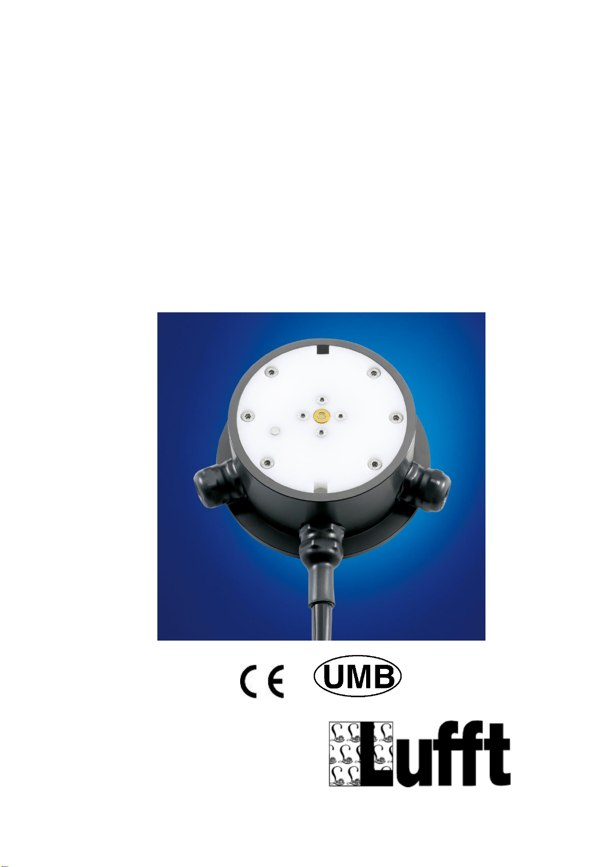
Operating Manual ARS31(Pro)-UMB
G. Lufft Mess- und Regeltechnik GmbH, Fellbach, Germany 2
Contents
1Please read before commissioning ........................................................................................................3
1.1 Symbols used.....................................................................................................................................3
1.2 Safety instructions ..............................................................................................................................3
1.3 Designated use...................................................................................................................................3
1.4 Guarantee...........................................................................................................................................3
1.5 Incorrect use.......................................................................................................................................3
1.6 Nomenclature .....................................................................................................................................3
2Differences between ARS31Pro-UMB/ARS31-UMB..............................................................................4
3Device description ..................................................................................................................................4
3.1 Method of operation ARS31Pro-UMB/ARS31-UMB...........................................................................4
3.2 Additional features of ARS31Pro-UMB...............................................................................................5
3.3 Availability of measurement values....................................................................................................5
4Installation...............................................................................................................................................7
4.1 Preparation.........................................................................................................................................7
4.2 Installation...........................................................................................................................................7
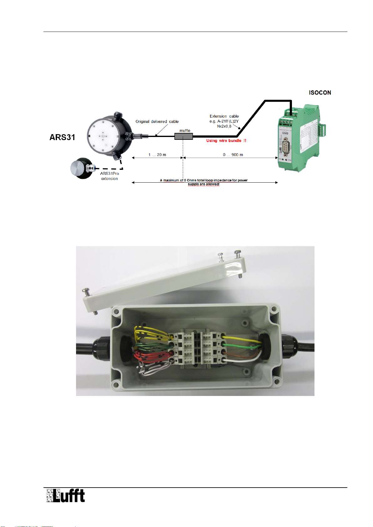
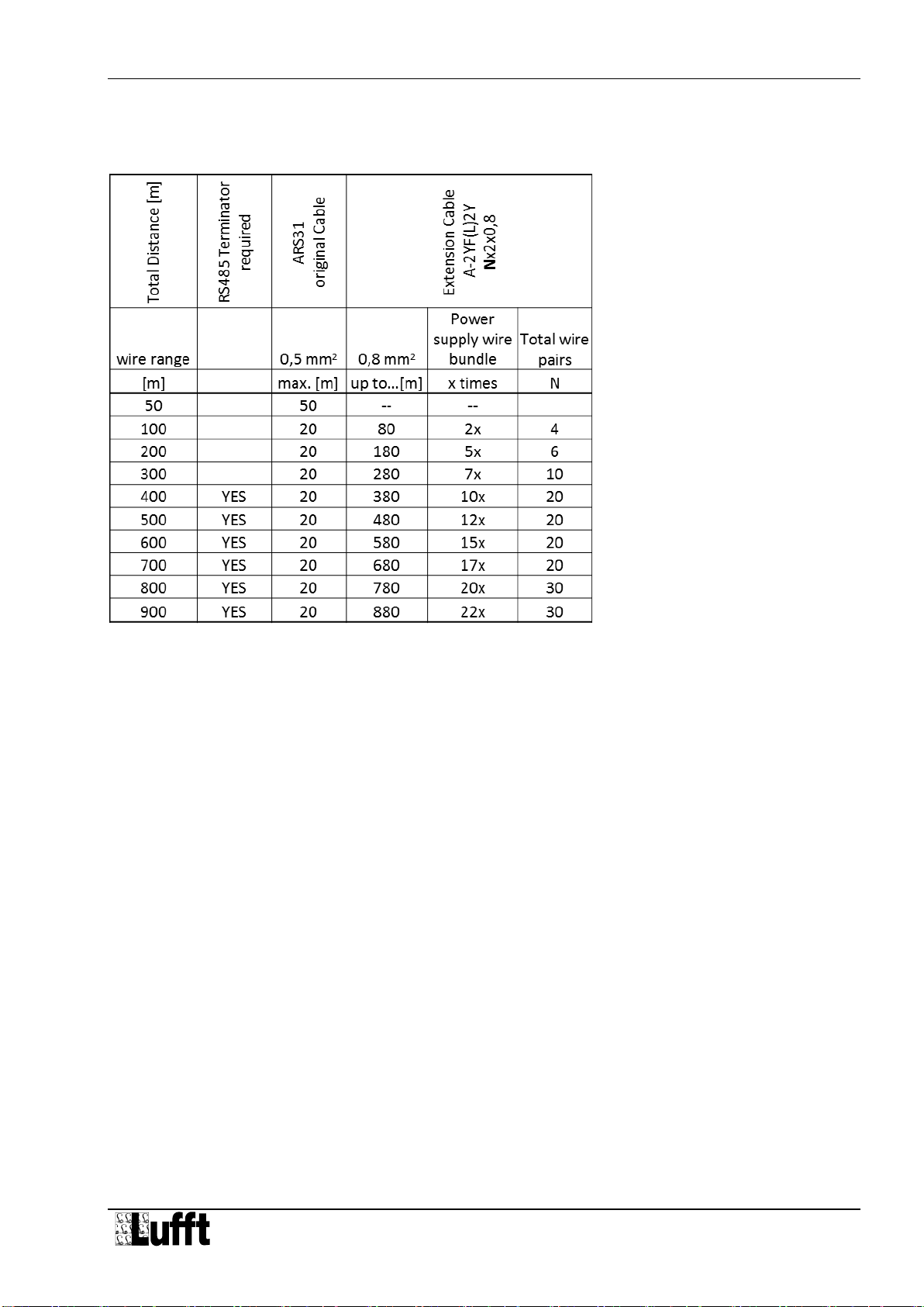
4.3 Connecting the cable........................................................................................................................11
4.4 Commissioning and testing ..............................................................................................................14
5Maintenance.........................................................................................................................................15
5.1 Replacing the sensor system ...........................................................................................................15
5.2 Connections......................................................................................................................................16
6Configuration ........................................................................................................................................18
6.1 Factory settings ................................................................................................................................18
6.2 Using PC configuration software......................................................................................................18
6.3 Firmware update...............................................................................................................................22
7Communication.....................................................................................................................................23
7.1 Binary protocol..................................................................................................................................23
7.2 ASCII protocol...................................................................................................................................25
7.3 Channel assignment for the data request ........................................................................................26
7.4 Mapping standards...........................................................................................................................28
8Technical data ......................................................................................................................................29
8.1 Measurements..................................................................................................................................29
8.2 Storage conditions (complete sensor)..............................................................................................29
8.3 Operating conditions.........................................................................................................................30
8.4 Electrical data...................................................................................................................................30
8.5 Interfaces..........................................................................................................................................30
8.6 Mechanical data (excluding cable)...................................................................................................30
9EC Certificate of Conformity.................................................................................................................31
10 Troubleshooting....................................................................................................................................32
11 Service and maintenance.....................................................................................................................33
12 Disposal................................................................................................................................................33
13 Manufacturer.........................................................................................................................................34
13.1 Technical support .............................................................................................................................34
Version history:
Technical data modified, adjustment to current public standards
Supplements to the cable length and to the installation
Extension cable table was added
Modification of Certificate of Conformity, clarification of the technical data (freezing temperature)
Supplements to the cable length and power supply, integration of ARS31-UMB