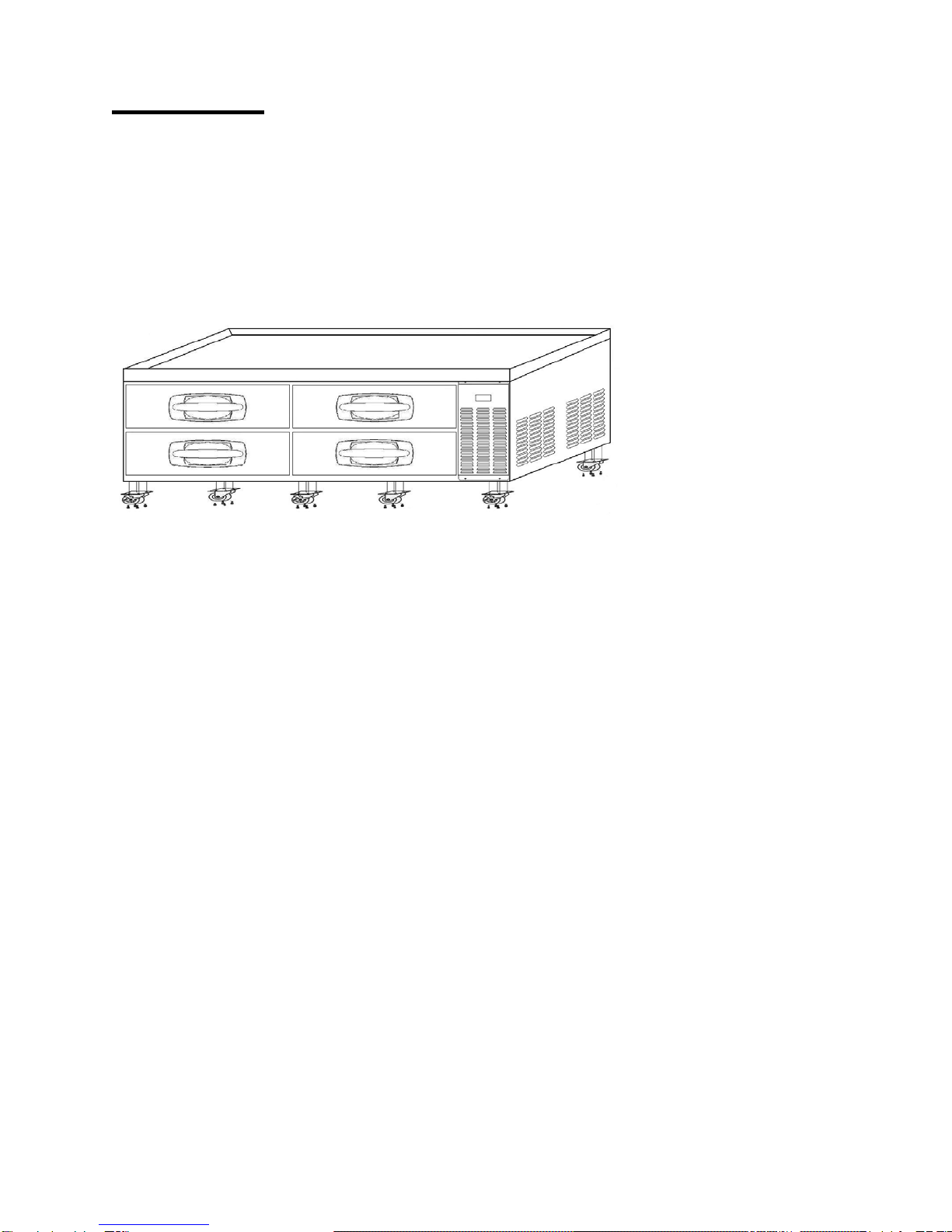
Master Bilt CB36 Installation and operating instructions

05/15 Rev. H147774
1
CHEF BASE CABINETS
Installation, Operation and Maintenance Instructions
INSPECTION
When the equipment is received, all items should be carefully checked against the Bill
of Lading to ensure all crates and cartons have been received. Do not sign the freight
bill clear until the freight has been properly inspected for damage. All units should be
inspected for damage including concealed damage by uncrating immediately. If any
damage is found, it should be reported to the carrier at once, noted on the Bill of Lading
and a claim should be filed with the carrier. This equipment has been inspected and
tested in the manufacturing facility and has been crated in accordance with
transportation rules and guidelines. The manufacturer is not responsible for freight loss
or damages.
INSTALLATION
The exterior top of the cabinet has been protected by a plastic covering. Peel this
protective covering before installation. After removing the covering, clean the interior
and exterior surfaces of the unit with soap and water and a rinse with clean water. Do
not use chlorinated cleaners on the surfaces as they can cause corrosion.
The refrigeration system located on the side of the unit requires free air access for
proper operation. Allow a minimum of seven inches between the back of the cabinet
and the wall. The equipment is designed to accept heat generating cooking equipment if
the equipment is properly installed with legs (supplied by the cooking equipment
manufacturer). A minimum clearance of 4 inches is required between the bottom of the
cooking equipment heating element and the cabinet top. Failure to provide adequate
clearance voids manufacturer warranty. Installation of a heat shield (supplied by others)
is recommended for optimum performance.
Confirm that the proposed electrical outlet has the correct voltage, frequency and
current carrying capacity for the requirements of the unit. This information is noted on
the data plate on the inside left wall of the unit. The unit should be isolated on a circuit.
Do not use an extension cord to get power to the unit. Improper electrical installations
will void the compressor warranty. To prevent shock and fire, be sure the unit is properly
grounded.
The temperature controller is located inside the refrigerated compartment in the back
right top corner. The default temperature is set at “normal”. Adjust the temperature to fit
your needs. It is not recommended that the cabinet be run colder than +34°F.

05/15 Rev. H147774
2
CAUTION!
DO NOT SIT OR STAND ON TOP OF THESE CABINETS AND
DO NOT USE THE DRAWERS AS A STEP.
SERIOUS INJURIES CAN OCCUR.
Install casters per the following diagram.
Note: Install casters with brakes to the front of the cabinet.
MAINTENANCE
General Cleaning
Beginning with the initial installation, the interior surfaces of the cabinet should be
periodically cleaned with a solution of warm water and baking soda. This solution will
remove any odors from spillage that has occurred. The exterior of the cabinet should
also be cleaned frequently with a commercial stainless steel cleaner, glass cleaner or
mild soap solution. Do not use chlorinated cleaners on the stainless steel surfaces.
Note: do not use stainless steel cleaners or other solvent-based chemicals on the
plastic parts (door handle or trim strips) as they can cause failure. Use mild soap and
warm water on plastic parts.
The door gaskets should be cleaned in place with a mild soap solution to extend their
life.
Condenser Coil Cleaning
Prior to cleaning the condenser coil disconnect the unit from power. Periodic cleaning
of the condenser coil will aid the heat transfer of the refrigeration system and increase
its efficiency. To accomplish this, remove the front grill from the cabinet. The
condenser coil is located behind the grill. Use a soft bristled brush to remove any dirt
particles that are on the fins of the condenser coil. Use a vacuum cleaner or
compressed air to remove the loosened particles. Replace the grill and reconnect the
unit to power. Failure to clean the condenser coil can lead to performance loss and
compressor failure. It is recommended a minimum of every three months.

05/15 Rev. H147774
3
TROUBLESHOOTING
Problem Remedy
Compressor will
not start
·Check the power cord and make sure it is plugged in.
·Check the temperature controller. If it is in the “OFF” position,
turn it clockwise to set a desired temperature.
Poor
performance
·Move the unit from direct sunlight.
·Move the unit away from heating devices.
·Install the unit in a well ventilated place, with at least 7 inches of
clearance on all sides.
·Clean the condenser if heavy dust is collected.
·Clear contents from blocking the air duct.
·Check the temperature controller for incorrect setting.
·Check the refrigerant level, it may need to be charged.
·Check the door and be sure it is completely closed.
Unit noisy
·Install the unit on a level surface.
·Maintain 7 inches of clearance from the wall.
·Check for loose part or mounting.
·Keep the tubing free from any contact to avoid rattle.
Condensation on
cabinet exterior
and/or floor
·Reduce humidity where the unit is installed.
·Repair or replace the gasket on the door.

05/15 Rev. H147774
4
SPECIFICATIONS
* Includes 5 inches for casters.
** Above specifications are subject to change without prior notice for quality improvement.
*** Relative humidity should be kept between 30% - 60%, maintaining a dew point of +50°F or less.

05/15 Rev. H147774
5

05/15 Rev. H147774
6
▣Chef Base –Drawer Structure
Small drawers
Large drawers
Tray Frame Assy –small –ITEM 6
Door Gasket –small –ITEM 13
Door Assembly-small –ITEM 10
Supporter Pan – A – ITEM 32
Tray Frame Assy –big –ITEM 5
Door Gasket –big –ITEM 13
Door Assembly-big –ITEM 9
Supporter Pan – A – ITEM 32
▣Chef Base –Drawer Rail Structure
Cabinet Rail -Left –ITEM 1
Crossbar Rail –Left –ITEM 3
Crossbar Rail –Right –ITEM 4 Cabinet Rail –Right –ITEM 2

05/15 Rev. H147774
7
▣Chef Base –Internal Structure
REF-Thermostat Kit
ITEM 20
EVAP. FAN GUARD
Small –ITEM 35
Large –ITEM 36
Large –ITEM 37
Drain Pan(Drip)
EVAP. DUCT (3F)
1 Fan –ITEM 38
2 Fan –ITEM 39
3 Fan –ITEM 40
EVAPORATOR
Small –ITEM 16
Large –ITEM 17
Evaporator Fan Motor
ITEM 29
▣Chef Base –Machine Room
Disassembly
REAR COVER
ITEM 34
SIDE MACHINE COVER
ITEM 32
FRONT COVER
ITEM 33
INDICATOR
ITEM 27
▣Chef Base –Machine Room
Condensing Unit Disassembly -2
Unit Base
Condenser -ITEM 14
-ITEM 15
Evaporating pan (dish)
Hot Pipe –ITEM 15
Condenser fan motor –Assembly
ITEM 28
Compressor –ITEM 21
-ITEM 22
CAPILLARY & SUCTION PIPE ASSY –ITEM 19
Dryer –ITEM 18
HARNESS MAIN
ITEM 23
HARNESS COMP
Compressor Type [SD162C-L1U]
ITEM 24
HARNESS COMP
Compressor type [SK1A1C-L1U2]
ITEM 25

05/15 Rev. H147774
8
▣Chef Base –Wiring Diagram
[CB36, CB48, CB53, CB60, CB72]
▣Chef Base –Wir ing Diagr am
[CB84,CB96]
This manual suits for next models
6
Table of contents
Other Master Bilt Commercial Food Equipment manuals
Popular Commercial Food Equipment manuals by other brands

edenox
edenox VEPS-72 instruction manual

Hussmann
Hussmann KH14 installation manual

Victor
Victor HMU50 operating manual

Rocam Losi
Rocam Losi EROS 4 R/M INSTRUCTION MANUAL ASSEMBLY, INSTALLATION, USE AND MAINTENANCE

Manitowoc
Manitowoc Frymaster FilterQuick FQE30 Service manual

Vollrath
Vollrath Cayenne FMA7026 Operator's manual