MasterCraft 55-4504-8 User manual

Owner's Manual
12" Mini Wood Lathe
55-4504-8
01/07
Toll-Free Helpline:
1-800-689-9928

SECTION PAGE
I. Technical Data . . . . . . . . . . . . . . . . . . . . . . . . . . . . . . . . . . . . . . . . . . . . . . . . . . . . . .2
II. General Safety Rules . . . . . . . . . . . . . . . . . . . . . . . . . . . . . . . . . . . . . . . . . . . . . . . .3
III. Specific Safety Rules for the Mini Wood Lathe . . . . . . . . . . . . . . . . . . . . . . . . . . . . . .5
IV. Electrical Information . . . . . . . . . . . . . . . . . . . . . . . . . . . . . . . . . . . . . . . . . . . . . . . . .6
V. Diagram and Location of Parts . . . . . . . . . . . . . . . . . . . . . . . . . . . . . . . . . . . . . . . . . .8
VI. Assembly and Adjustment Instructions . . . . . . . . . . . . . . . . . . . . . . . . . . . . . . . . . . . .9
VII. Operating Instructions . . . . . . . . . . . . . . . . . . . . . . . . . . . . . . . . . . . . . . . . . . . . . . .12
VIII. Maintenance . . . . . . . . . . . . . . . . . . . . . . . . . . . . . . . . . . . . . . . . . . . . . . . . . . . . . .15
IX. Parts List . . . . . . . . . . . . . . . . . . . . . . . . . . . . . . . . . . . . . . . . . . . . . . . . . . . . . . . . .16
X. Exploded View . . . . . . . . . . . . . . . . . . . . . . . . . . . . . . . . . . . . . . . . . . . . . . . . . . . . .17
XI. Warranty . . . . . . . . . . . . . . . . . . . . . . . . . . . . . . . . . . . . . . . . . . . . . . . . . . . . . . . . .18
I. Technical Data
Table of Contents
MINI WOOD LATHE
MODEL NUMBER: 55-4504-8
MOTOR: 120 V AC, 60 Hz, 3 A
SPEEDS: 500–3500 RPM
SWITCH: Removable key type
DISTANCE BETWEEN CENTRES: 12" (30 cm)
SWING OVER BED: 8" (20 cm)
DRIVE SPINDLE: 1" (25 mm), 8 TPI thread
DRIVE SPINDLE THROUGH HOLE: 3/8" (10 mm)
TAILSTOCK SPINDLE THROUGH HOLE: 3/8" (10 mm)
TAILSTOCK SPINDLE TRAVEL: 1 1/2" (4 cm)
HEADSTOCK SPUR: Spur centre, Morse #1 taper
TAILSTOCK CENTRE: Ball bearing cap centres, Morse #1 taper
POWER CORD: 8' (2.4 m)
OVERALL SIZE: 30 5/8 x 4 13/16 x 13 1/2"
(77.8 x 12.2 x 33.4 cm)
NET WEIGHT: 43 lb (19.5 kg)
CSA: 184892
2

Safety is a combination of common sense, staying alert, and knowing how the mini wood
lathe works.
1. READ this entire Owner's Manual and become familiar with the information that it
contains. Learn the applications, limitations, and possible hazards associated with the
lathe.
2. AVOID DANGEROUS CONDITIONS. Do not use power tools in wet or damp areas, and
DO NOT expose them to rain. Keep work areas well-lit.
3. DO NOT use power tools in the presence of flammable liquids or gases.
4. Keep the work area clean, uncluttered, and well-lit. Do not work on floor surfaces that
are slippery from sawdust or wax.
5. KEEP BYSTANDERS AT A SAFE DISTANCE FROM the work area, especially when the
tool is in use. Do not allow children or pets near the lathe.
6. DO NOT FORCE THE TOOL to do a job that it was not designed to do.
7. DRESS FOR SAFETY. Do not wear loose clothing, gloves, neckties, or jewellery (rings,
watches, etc.) when operating the tool. Loose clothing and other items can get caught in
moving parts and draw the operator in. ALWAYS wear non-slip footwear, and tie back
long hair.
8. WEAR A FACE MASK OR A DUST MASK, because the turning operation produces
dust.
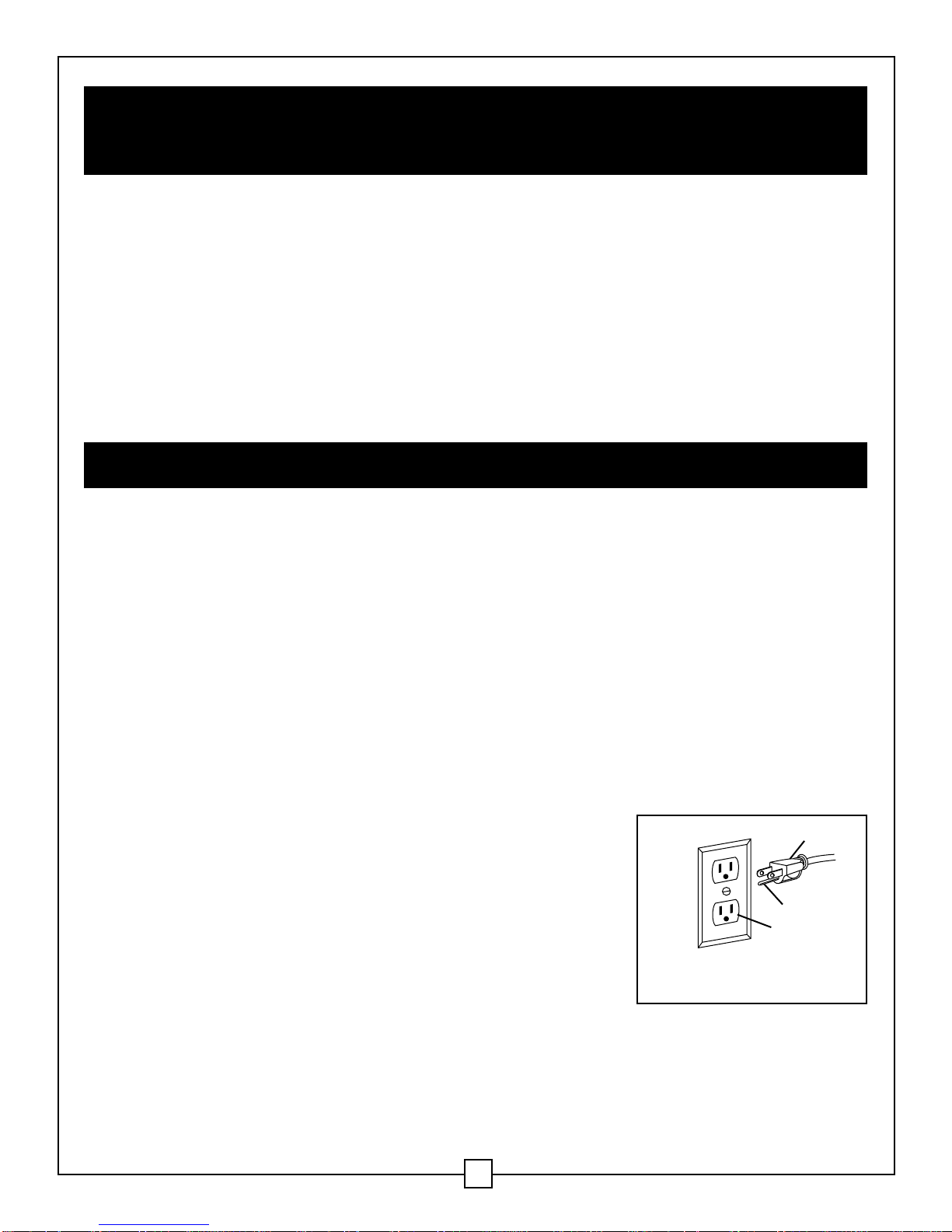
9. Unplug the power cord plug from the electrical outlet when making adjustments,
changing parts, and cleaning or working on the tool.
10. KEEP ALL GUARDS IN PLACE AND IN WORKING ORDER.
11. AVOID ACCIDENTAL START-UPS. Verify that the power switch is in the OFF position
before plugging in the power cord.
12. REMOVE ADJUSTMENT TOOLS. Verify that all adjustment tools are removed from the
lathe before turning it on.
13. NEVER LEAVE A LATHE UNATTENDED WHEN IT IS IN USE. Turn the power switch to
the OFF position. DO NOT leave the tool until it has come to a complete stop.
WARNING: IN ORDER TO AVOID MISTAKES THAT COULD CAUSE SERIOUS INJURY,
READ THE FOLLOWING STEPS CAREFULLY AND UNDERSTAND THEM
THOROUGHLY BEFORE PLUGGING IN THE LATHE.
Keep this Owner's Manual in a safe place for future reference.
II. General Safety Rules
3

14. DO NOT STAND ON THE TOOL. Serious injury could result if the tool tips or is
accidentally jarred. Do not store anything above or near the tool.
15. DO NOT OVERREACH. Keep proper footing and balance at all times. Wear oil-resistant
rubber-soled footwear. Keep the floor clear of oil, scraps, and other debris.
16.MAINTAIN TOOLS PROPERLY. ALWAYS keep tools clean and in good working order.
Follow the instructions for lubricating and changing accessories.
17.CHECK FOR DAMAGED PARTS. Check for misalignment, jamming, breakage, and
improper mounting of moving parts, and for any other conditions that may affect the
operation of the tool. Repair or replace any part that is damaged before using the lathe.
18.MAKE THE WORKSHOP CHILDPROOF. Use padlocks and master switches, and remove
starter keys.
19.DO NOT operate the tool when under the influence of drugs, alcohol or medication that
may affect your ability to use the tool properly.
Keep this Owner's Manual in a safe place for future reference.
II. General Safety Rules (continued)
4
WARNING: DUST GENERATED FROM CERTAIN MATERIALS CAN BE HAZARDOUS TO
THE HEALTH. OPERATE THE LATHE IN A WELL-VENTILATED AREA, AND ENSURE
THAT PROPER DUST REMOVAL IS PROVIDED. WEAR A FACE MASK OR A DUST MASK
WHEN OPERATING THE LATHE.
WEAR EYE PROTECTION THAT CONFORMS WITH CSA
REQUIREMENTS.
FLYING DEBRIS can cause permanent eye damage.
Prescription eyeglasses are not an adequate substitute for proper
eye protection.
WARNING: EXPOSURE TO EXCESSIVE NOISE LEVELS CAN RESULT IN PERMANENT
HEARING LOSS. WEAR EAR PROTECTION (SAFETY EAR MUFFS OR EAR PLUGS) IN
ORDER TO REDUCE NOISE LEVELS WHEN OPERATING THE LATHE.

1. FOR SAFETY REASONS, read the entire instruction manual carefully before operating
the lathe.
2. WEAR eye protection.
3. DO NOT wear gloves, a necktie, or loose clothing.
4. TIGHTEN all locks before operating the lathe.
5. DO NOT mount a workpiece that has a split in it.
6. USE the lowest speed when starting a new workpiece.
7. READ the warning label that is attached to the lathe.
8. ROTATE the workpiece by hand before turning on the motor. The workpiece could split
and be thrown out of the lathe, if it strikes the tool rest.
9. WHEN TURNING A WORKPIECE, always rough the wood to round form at slow speed.
If the lathe vibrates while it is running, there is a risk that the workpiece will be thrown
or will be jerked out of the operator's hands.
10. DO NOT allow the turning tools to bite into the wood. The wood could split or be thrown
from the lathe.
11. When shaping a piece of stock, position the tool rest above the centreline of the lathe
12. DO NOT operate the lathe if it is rotating in the wrong direction. The workpiece must
always be rotating toward the operator.
13. BEFORE ATTACHING a workpiece to the faceplate, always rough it out to make it as
round as possible. This will minimize vibrations while the piece is being turned. Fasten
the workpiece to the faceplate securely. Failure to do so could result in the workpiece
being thrown from the lathe.
14. POSITION the hands so that they will not slip onto the workpiece.
15. REMOVE all loose knots in the stock before mounting it between the centres or on
the faceplate.
Keep this Owner's Manual in a safe place for future reference.
III. Specific Safety Rules for the Mini Wood Lathe
5
WARNING: DO NOT OPERATE THE LATHE UNTIL IT IS COMPLETELY ASSEMBLED
AND INSTALLED ACCORDING TO THE INSTRUCTIONS.

III. Specific Safety Rules for the Mini Wood Lathe
(continued)
16. DO NOT LEAVE THE LATHE UNATTENDED WHEN IT IS RUNNING. Do not leave the
work area until the motor has come to a complete stop.
17. HANG turning tools on the wall beyond the tailstock end of the lathe. Do not lay them on
the bench so that the operator must reach over the revolving workpiece to select them.
18. KEEP A FIRM HOLD, and remain in control of the cutting tool at all times. Take special
precautions when shaping a section of stock in which knots or voids are found.
19. COMPLETE the hand-sanding of all workpieces before removing them from the lathe.
Keep this Owner's Manual in a safe place for future reference.
IV. Electrical Information
GROUNDING INSTRUCTIONS
IN THE EVENT OF A MALFUNCTION OR BREAKDOWN, grounding provides the path of
least resistance for electric current in order to reduce the risk of electric shock. This tool is
equipped with an electric cord that has an equipment grounding conductor and a grounding
plug. The plug MUST be plugged into a corresponding outlet that is properly installed and
grounded in accordance with ALL local codes and ordinances.
DO NOT ALTER THE PLUG. If it does not fit into the outlet, have the proper type of outlet
installed by a licenced electrician.
IMPROPER CONNECTION of the equipment grounding conductor can result in a risk of
electric shock. The conductor with the green insulation (with or without yellow stripes) is the
equipment grounding conductor. If it is necessary to repair or replace the power cord or plug,
do not connect the equipment grounding conductor to a live terminal.
CHECK with a licenced electrician if the grounding instructions
are not completely understood, or if there is any question as to
whether the tool is properly grounded.
USE ONLY A THREE WIRE EXTENSION CORD that is
equipped with a 3-pronged plug, and plug it into an outlet that
can accept the tool's power cord as shown in Fig. A. Repair or
replace a damaged or worn power cord or extension cord
immediately.
CAUTION: ALWAYS VERIFY THAT THE OUTLET THAT IS USED IS PROPERLY
GROUNDED. IF THERE IS ANY DOUBT, HAVE IT INSPECTED BY A LICENCED
ELECTRICIAN.
1
3
2
1 - 3-prong plug 2 - Properly grounded outlet
3 - Grounding prong
Fig. A
6
1. 3-pronged outlet
2. Properly grounded outlet
3. Grounding plug

WARNING: THIS LATHE IS INTENDED FOR INDOOR USE ONLY. DO NOT EXPOSE IT
TO RAIN OR USE IT IN A DAMP LOCATION.
GUIDELINES FOR USING EXTENSION CORDS
Verify that the extension cord is in good condition. When using an extension cord, be sure to
use one that is heavy enough to carry the current that the tool will draw. Using an undersized
cord will cause a drop in line voltage, which will result in a loss of power and overheating.
The table below shows the correct size to use, according to the length of the extension cord
and the nameplate amperage rating. When in doubt, use the next heavier gauge. The smaller
the gauge number, the heavier the cord.
Verify that the extension cord is properly wired and in good condition. Always replace a
damaged extension cord or have it repaired by a qualified person before using it. Keep
extension cords from sharp objects, excessive heat, and damp or wet areas.
Use a separate electric circuit for operating power tools. This circuit should consist of not
less than a #12 wire, and should be protected by a 15 A time-delayed fuse. Before plugging
the lathe into the electrical outlet, verify that the switch is in the OFF position and that the
electric current is rated the same as the current that is stamped on the motor nameplate.
Running the lathe at a lower voltage will damage the motor.
WARNING: IN ORDER TO PROTECT THE OPERATOR FROM ELECTRIC SHOCK, THIS
TOOL MUST BE GROUNDED WHILE IN USE.
Keep this Owner's Manual in a safe place for future reference.
IV. Electrical Information (continued)
7
Minimum Gauge for Extension Cords (AWG)
(120 volts circuits only)
Amperage Rating Total Length of Cord in feet (metres)
More Than Not More Than 25' (7.6 m) 50' (15 m) 100' (30.4 m) 150' (45.7 m)
0 6 18 16 16 14
6 10 18161412
10 12 16 16 14 12
12 16 14 12 Not Recommended

V. Diagram and Location of Parts
8
A Headstock
B Faceplate
C Tool rest
D Tailstock lock lever
E Tailstock cup centre
F Spindle lock lever
G Hand wheel
H Tailstock
I Tool rest lock lever
J Base lock lever
K Tool rest base
L Motor
M Speed control knob
N ON/OFF switch
O Reset button
A
B
CD
EF
G
H
I
J
K
L
M
N
0

VI. Assembly and Adjustment Instructions
Unpacking (Fig. 1)
CAUTION: THE MINI LATHE IS HEAVY, AND MUST BE LIFTED WITH THE HELP OF
ANOTHER PERSON.
1. Carefully remove the mini lathe and all loose parts from the box.
2. Lay out all of the parts and check them against the parts listed below. Examine all
parts carefully.
For your safety, the lathe must be completely assembled before it is plugged it into the
power supply.
WARNING: IF THERE ARE ANY MISSING OR DAMAGED PARTS, DO NOT PLUG THE
LATHE IN UNTIL ALL MISSING OR DAMAGED PARTS ARE REPLACED.
9
A Mini wood lathe
B Headstock spur centre
C Tailstock cup centre
D Push-out rod
E Flat wrench
F Tool rest
G Faceplate, 5 3/4" (14.5 cm) diameter
H 5/32" (4 mm) hex key
Hardware for mounting the lathe: 3 hex bolts
and washers (not shown)
Fig. 1 A
G
F
H
EB
CD

Mounting the lathe on a workbench (Fig. 2)
1. Measure and mark three hole centres in a clear space on the workbench, as shown in
Fig. 2.
2. Drill clearance holes through the workbench. Position the lathe on the workbench.
3. Install the bolts and washers (included in the hardware bag) from underneath the
workbench, and into the tapped holes in the bottom of the lathe frame.
Note: In order to hold the lathe securely, the bolts must extend at least 1" (2.5 cm) into
the frame.
Spring-loaded lock levers (Fig. 3)
The spring-loaded lock levers for the tailstock spindle
and the tool rest are constructed using four pieces.
The shoulder screw (1) passes through the spring (2)
and the handle lever (3) and bolt (4). If either of the lock
levers has come loose from the lathe or has come apart
in shipping, reassemble it and thread into place.
Note: The spring-loaded handles on the lathe are
designed to minimize interference with other parts of the
lathe or the workpiece. Push the handle lever in and turn
clockwise in order to tighten the handle. Pull the handle
lever out in order to disengage the threaded shaft, which
allows the lever handle to be repositioned so that it is out of the way.
VI. Assembly and Adjustment Instructions (continued)
10
WARNING: THE LATHE MUST BE BOLTED TO A WORKBENCH. OPERATING A LATHE
THAT IS NOT BOLTED DOWN MAY RESULT IN SERIOUS INJURY.
Fig. 2
Fig. 3
12
34

VI. Assembly and Adjustment Instructions (continued)
1
3
1
2
Using a faceplate
Mount the workpiece onto the faceplate using brass
wood screws. Do not use screws that are long
enough to enter the area of the workpiece where
material is to be removed.
Note: The faceplate has an open centre, so that
the drill bit can go completely through the
workpiece when drilling through a workpiece from
the tailstock.
Installing or removing a faceplate (Fig. 4)
1. When installing a faceplate (1), thread it onto the
end of the headstock spindle and hand-tighten it.
2. Place the wrench (2) over the flats on the
faceplate.
Note: The headstock spindle is belt driven, so
it will turn freely if it is not held stationary while
the faceplate is tightened or loosened.
3. Insert the tip of the push-out rod (3) into one of
the slots in the side of the headstock spindle.
4. While gripping the push-out rod firmly, turn the
wrench in order to either tighten or loosen the
faceplate.
5. Remove the push-out rod and wrench. If the
faceplate is being removed, continue to turn it
until it comes off the spindle threads.
Installing the spur and the centre (Fig. 5 and 6)
1. Insert the shaft of the spur (1) into the hollow
centre of the headstock spindle (Fig. 5).
2. Insert the shaft of the tailstock centre into the
hollow centre of the tailstock spindle (Fig. 6).
WARNING: DO NOT OPERATE THE LATHE UNTIL IT IS COMPLETELY ASSEMBLED
AND ADJUSTED ACCORDING TO THE INSTRUCTIONS.
11
Fig. 4
Fig. 5
Fig. 6 1

VII. Assembly and Adjustment Instructions (continued)
VIII. Operating Instructions
Removing the spur or the centre (Fig. 7)
1. Insert the push-out rod (1) into the far end
of the headstock spindle or the tailstock
spindle until it comes into contact with the
shaft of the spur or centre.
2. Tap the end of the push-out rod (1) until
the spur or centre comes loose.
12
1
Fig. 7
Variable speed control box
The variable speed control box contains the electrical connections to the motor. It features
three external controls: the speed control knob, the ON/OFF switch, and the circuit breaker
reset button.
Speed control knob (Fig. 8)
The speed control knob (1) is used to set the
speed of the lathe to suit the weight of the
workpiece or the type of tool that is being
used.
1. After the lathe is started, turn the knob
clockwise in order to increase the spindle
speed (up to the maximum RPM). Turn the
knob counter-clockwise in order to
decrease the spindle speed (down to the
minimum RPM).
2. Adjust the knob until the desired rotation
speed for the workpiece is reached.
Fig. 8
3
1
4
2
WARNING: ALWAYS SET THE SPEED CONTROL KNOB TO ITS LOWEST SETTING
(COUNTER-CLOCKWISE) BEFORE STARTING THE LATHE. NEVER START THE LATHE
AT MAXIMUM SPEED. THERE IS A DELAY OF UP TO 3 SECONDS AFTER THE LATHE
IS STARTED BEFORE THE MOTOR IS ACTIVATED.

VII. Operating Instructions (continued)
13
ON/OFF Switch (Fig. 8)
The ON/OFF switch (2) controls the supply of electrical power to the lathe’s motor. The
safety key (3) must be placed in the switch before the switch will operate.
1. Move the switch to the ON position to start the motor. The electric current is applied to
the motor immediately. There is an activation delay of up to 3 seconds before the motor
begins to turn the headstock spindle. The amount of time it takes for the motor to reach
the speed that is set by using the speed control knob depends on the size and weight of
the workpiece.
2. Move the switch to the OFF position to stop the motor. Electric current is immediately
disconnected, but the spindle and workpiece will continue to spin for several seconds.
Note: The safety key (3) can only be removed from the switch when it is in the
OFF position. Once the key is removed, the switch is locked in that position, and
the lathe cannot be started. Store the key in a safe place when the lathe is left
unattended.
CAUTION: DO NOT LEAVE THE LATHE UNATTENDED UNTIL IT HAS COME TO
A COMPLETE STOP.
Reset button (Fig. 8)
The reset button (4) is used to restart the motor after the motor has shut off due to
overloading or low voltage. Follow these steps if the motor stops while the lathe is in use:
1. Turn the ON/OFF switch (1) to the OFF position, and wait approximately 5 minutes for
the motor to cool down.
2. Press the reset button (4), and then turn the switch (1) to the ON position.
WARNING: IF THE MOTOR SHUTS OFF UNEXPECTEDLY, UNPLUG THE LATHE FROM
THE OUTLET, VERIFY THAT THE ON/OFF SWITCH IS IN THE OFF POSITION, AND
ALLOW THE MOTOR TO COOL DOWN BEFORE ATTEMPTING TO RESTART THE
LATHE. OVERHEATING MAY BE CAUSED BY MISALIGNED PARTS OR BY A DULL
CHISEL. INSPECT THE LATHE FOR PROPER SETUP BEFORE USING IT AGAIN.

VII. Operating Instructions (continued)
Tailstock (Fig. 9)
1. Move the tailstock (5) by loosening the lock
lever (1) and pushing the tailstock to the
desired position on the bed. Lock it in place
by tightening the lock lever (1).
2. The spindle can extend up to 2 1/2"
(6.4 cm) from the tailstock housing. Move
the tailstock spindle (4) by loosening the
spindle lock lever (2) and then turning the
hand wheel (3) clockwise in order to
extend the spindle, or turn it counter-
clockwise in order to retract the spindle.
Lock levers (1) and (2) before operating
the lathe.
3. The tailstock spindle is hollow, and can be
accessed from the handwheel end. Use the
push-out rod to remove the centre cup or
to drill holes through the centre of a
workpiece that is mounted on a faceplate.
Tool rest (Fig. 10)
1. Move the tool rest base (1) by loosening
the lock lever (4) and then moving the
base to the right or left, and back or front.
Tighten the lock lever (4) when the tool
rest base is in the desired position.
2. In order to adjust the angle of the tool
rest (2), loosen the lock lever (3), move
the tool rest to the desired position, and
then retighten the lock lever.
3. In order to change to the other tool rest,
loosen the lock lever (3) and pull the tool
rest (2) out of the tool rest base, insert the
other tool rest, adjust it to the desired
position, and then retighten the lock
lever (3).
IMPORTANT: VERIFY THAT THE TOOL REST IS ADJUSTED SO THAT IT IS AS CLOSE TO
THE WORKPIECE AS POSSIBLE. ROTATE THE WORKPIECE BY HAND IN ORDER TO
CHECK THE CLEARANCE BEFORE STARTING THE LATHE.
14
Fig. 10
1
2
3
4
Fig. 9
1
23
4
5

VIII. Maintenance
1. Blow out any dust that accumulates inside the motor, the housing, and the bed assembly
on a regular basis. If the tailstock has been used as a guide for drilling through the centre
of a workpiece, blow the sawdust or shavings out of the centre of both spindles.
2. Apply a coat of automotive wax to the bed in order to help keep the surface clean and to
facilitate the movement of the tool rest and tailstock.
3. Lubricate the spring levers and other threaded parts periodically in order to make these
parts easier to operate.
WARNING: FOR SAFETY REASONS, TURN THE SWITCH TO THE OFF POSITION AND
REMOVE THE PLUG FROM THE POWER SOURCE BEFORE PERFORMING ANY
MAINTENANCE WORK OR LUBRICATING THE LATHE.
15

IX. Parts List
16
No. Description Qty No. Description Qty
1 Screw M4 x 8 9
2 Flat washer 4 9
3 Cover 1
4 Nut 1
5 Pulley 1
6 Screw M5 x 10 1
7 Bearing 6004-2Z 2
8 Power cable 1
9 Retainer 42 2
10 Headstock 1
11 Spindle 1
12 Face plate 1
13 Spur centre 1
14 Hex bolt M4 2
15 Compression spring 2
16 Handle 2
17 Jointer 1
18 Screw M4 x 14 2
19 Tool rest 1
20 Tool rest support 1
21 Eccentricity shaft (A) 1
22 Retainer B 1
23 Bolt 2
24 Handle 2
25 Compression spring 2
26 Screw M4 1
27 Shaft sleeve 1
28 Threaded rod (A) 1
29 Compression spring 2
30 Side block 2
31 Nut M8 2
32 Cap centre 1
33 Bearing 608 1
34 Cap centre rod 1
35 Tailstock 1
36 Screw M6x10 1
37 Screw M6x10 2
37A Cup assembly (includes parts 32, 33, and 34) 1
38 Tailstock spindle 1
39 Nut M6 1
40 Wheel 1
41 Handle 1
42 Screw 1
43 Handle cap 1
44 Eccentricity shaft (B) 1
45 Threaded sleeve 1
46 Threaded rod B 1
47 Plate 1
48 Hex bolt M6 x 16 2
49 Spring washer 6 2
50 Flat washer 6 2
51 Motor 1
52 Fix plate 1
53 Flat washer 5 4
54 Spring washer 5 4
55 Screw M5 x 12 4
56 Pulley 1
57 Hex bolt M8 x 30 2
58 Spring washer 8 3
59 Hex bolt M8 x 40 1
60 Flat washer 8 3
61 Tool bed 1
62 Clip 1
63 Belt 1
64 Switch box 1
65 Printed circuit board 1
66 Rotation label 1
67 Flat washer 7 1
68 Nut M7 1
69 Adjustable knob 1
70 Switch fix plate 1
71 Overload label 1
72 Tapping screw ST3.5 x 12 2
73 Overload protector 1
74 Switch 1
75 Push-out rod 1
76 Wrench 1
77 Wrench 1
Owner's Manual (not shown) 1
MASTERCRAFT®12" Mini Wood Lathe 55-4504-8

17
X. Exploded View
MASTERCRAFT®12" Mini Wood Lathe 55-4504-8
When servicing the Mastercraft®Mini Wood Lathe, use only Mastercraft®replacement
parts. Use of any other parts may cause damage to the product. Servicing of the wood lathe
should be performed by a qualified service technician.
WARNING: ANY ATTEMPT TO REPAIR OR REPLACE ELECTRICAL PARTS ON THIS
TOOL MAY BE HAZARDOUS. ALL REPAIRS SHOULD BE DONE BY A QUALIFIED
SERVICE TECHNICIAN.

XI. Warranty
This Mastercraft product carries a three (3) year repair warranty against defects in
workmanship and materials. At its discretion, Mastercraft Canada agrees to have any
defective part(s) repaired or replaced free of charge, within the stated warranty period,
when returned by the original purchaser with proof of purchase. This product is not
guaranteed against wear or breakage due to misuse and/or abuse.
This bench tool is not guaranteed if used for industrial or commercial purposes.
18
Table of contents
Other MasterCraft Lathe manuals
Popular Lathe manuals by other brands

SoapEguipment
SoapEguipment Willow Way instructions

Atrump
Atrump AL52 Operation & maintenance manual

Hurco
Hurco winmax Getting started guide

Baileigh Industrial
Baileigh Industrial WL-1847VS Operator's manual

pela tools
pela tools MJC1000 manual

Rikon Power Tools
Rikon Power Tools 70-1218VS Operator's manual