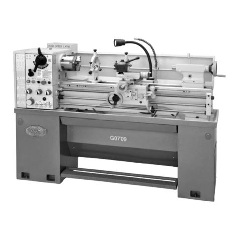
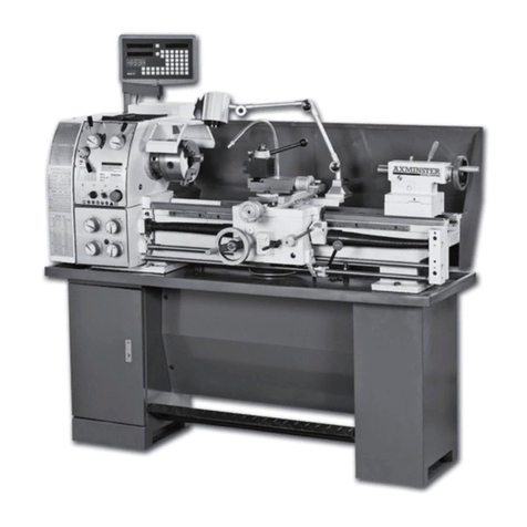
Promac 941A User manual

941A METAL LATHE
Original:
G
B
O
perating Instructions
M-BD-941A-M
Schweiz / Suisse
JPW (TOOL) AG
Tämperlistrasse 5
CH-8117 Fällanden Switzerland
www.promac.ch
France
TOOL France / PROMAC
57, rue du Bois Chaland, Z.I. du Bois Chaland
case postale 2935 FR-91029 Evry Cedex
www.promac.fr
2016-05

CE‐ConformityDeclaration
CE‐Konformitätserklärung
DéclarationdeConformitéCE
Product/Produkt/Produit:
MetalLathe
Metalldrehbank
Touràmétaux
941A
Brand/Marke/Marque:
PROMAC
Manufacturer/Hersteller/Fabricant:
JPW(Tool)AG,Tämperlistrasse5,CH‐8117Fällanden
Schweiz/Suisse/Switzerland
Weherebydeclarethatthisproductcomplieswiththeregulations
Wirerklärenhiermit,dassdiesesProduktderfolgendenRichtlinieentspricht
Parlaprésente,nousdéclaronsqueceproduitcorrespondauxdirectivessuivantes
2006/42/EC
MachineryDirective
Maschinenrichtlinie
DirectiveMachines
2014/30/EU
electromagneticcompatibility
elektromagnetischeVerträglichkeit
compatibilitéélectromagnétique
designedinconsiderationofthestandards
undentspechendfolgenderzusätzlicherNormenentwickeltwurde
etétédéveloppédanslerespectdesnormescomplémentairessuivantes
ENISO12100:2010
ENISO23125:2015
EN60204‐1:2006+A1:2009
EN61000‐6‐2:2005
EN61000‐6‐4:2007+A1:2011
ResponsiblefortheDocumentation/Dokumentations‐Verantwortung/RésponsabilitédeDocumentation:
HansjörgMeier
HeadProduct‐Mgmt./LeiterProdukt‐Mgmt./Resp.GestiondesProduits
JPW(Tool)AG
2016‐05‐24AlainSchmid,GeneralManager
JPW(Tool)AG,Tämperlistrasse5,CH‐8117Fällanden
Schweiz/Suisse/Switzerland

1

Table of Contents
INTRODUCTION......................................................................................................................4
MAIN PARAMETERS……………………………………………………………………......5
SECTION 1: SAFETY...............................................................................................................7
SECTION 2: POWER SUPPLY...............................................................................................9
Availability………………………………………………………………………9
Circuit Requirements…………………………………………………………..9
Grounding & Plug Requirements…………………………………………….10
Extension Cords……………………………………………………………….10
SECTION 3: SETUP……………………………………………………………………...…11
Unpacking……………………………………………………………………...11
Inventory………………………………………………………………………11
Clean Up……………………………………………………………………….12
Installation Dimensions……………………………………………………….12
Check Gearbox Oil……………………………………………………………12
Open the Cover………………………………………………………………..13
Install belt and Chang speeds………………………………………………...13
Test Run Lathe………………………………………………………………...14
SECTION 4: OPERATE……………………………………………………………………..15
General…………………………………………………………………………15
Controls…………………………………………………………...……………15
Removing/Installing Chuck or Faceplate…………………………………...16
Dead Centers…………………………………………………………………..17
Tailstock Positioning…………………………………………………………..18
Changing Tool Posts…………………………………………………………..18
Cross Slide…………………………………………………………………......18
Compound Slide……………………………………………………………….19
Carriage Handwheel…………………………………………………………..20
Half Nut Lever…………………………………………………………………20
Carriage/Cross Feed Lever…………………………………………...………20
Carriage Lock………………………………………………………………….20
Gearbox Levers………………………………...……………………………...20
Threads and Change gears……………………………………………………21
Left threads and reverse cutting feed………………………………………...21
Clutch Overload…………………………………………………...…………..22
SECTION 6: MAINTENANCE……………………………………………………….……..23
Lubrication…………………………………………………………………….23
Ball oilers............................................................................................................23
Feed Rate Gearbox Oil Reservoir....................................................................24
Gibs…………………………………………………………………………….25
Bearing Preload……………………………………………………………….26
2

IDENTIFICATION
The following is a list of controls and components on the lathe. Please take time to become
familiar with each term and its location. These terms will be used throughout the manual
and knowing them is essential to understanding the instructions and terminology used in
this manual.
1. Speed of Spindle(rpm)
2. Emergency Stop Switch
3. Lathe Power Indicator Light
4. Lathe ON/OFF switch
5. Lathe Forward/Reverse Switch
6. Lathe Chuck
7. Carriage Handwheel
8. Cross Slide Handwheel
9. Half Nut Lever
10. Tailstock Barrel Handwheel
11. Tailstock Clamp Bolt
12. Tailstock Center Lock
13. Compound Slide Handwheel
14. Work Light
15. Tool Post
16. Cross Slide
17. Carriage
18. Headstock Eyeshield
19. Work Table
20. Foot Switch
3

Model 941A Main Parameters
Product Dimensions:
Weight..................................................................................................................................180kg
Width (side-to-side) x Depth (front-to-back) x Height.....................................114 x 60 x 120 cm
Shipping Dimensions:
Type.............................................................................................................................Wood Crate
Content..............................................................................................................................Machine
Weight.............................................................................................................................. 225 kg.
Length x Width x Height..................................................................................123 x 73 x 140.cm
Electrical:
Minimum Circuit Size.........................................................................................................10 amp
Switch..................................................................................................................Forward/Reverse
Motors: Main
Type........................................................................................................................... …..YL7134
Outpower...................................................................................................................... …..550W
Amps......................................................................................................................4.2 amp (230V)
Speed............................................................................................................... 1400 RPM (50Hz)
Speeds.......................................................................................................................................... 1
Power Transfer .................................................................................................Belt Drive to Gear
Bearings..............................................................................Shielded and Permanently Lubricated
Main Specifications:
Operation Info
Swing Over Bed................................................................................................................250 mm
Distance Between Centers................................................................................................555 mm
Swing Over Cross Slide.....................................................................................................150 mm
Swing Over Saddle............................................................................................................210 mm
Compound Travel............................................................................................................... 70 mm
Carriage Travel..................................................................................................................565 mm
Cross Slide Travel..............................................................................................................100 mm
Max. Turning Tool Size................................................................................................10 x 10mm
Headstock Info
Spindle Bore.................................................................................................................... Φ20 mm
Spindle Size................................................................................................................ Φ52x11mm
Spindle Taper..................................................................................................................... MT#3
Number of Spindle Speeds..........................................................................................................6
Spindle Speeds......................................................(50Hz) 125, 210, 420,620, 1000, 2000 rpm
Spindle Bearings...........................................................................Tapered Roller + Ball Bearing
4

Tailstock Info
Tailstock Taper.....................................................................................................................MT#2
Tailstock Barrel Diameter...............................................................................................Φ30 mm
Tailstock Barrel Travel........................................................................................................50mm
Threading Info of Metric Lathe
Number of Longitudinal Feeds...................................................................................................2
Range of Longitudinal Feeds............................................................................0.1 or 0.2 mm/rpm
Number of Inch Threads.............................................................................................................. 6
Range of Inch Threads..................................................................................................10 - 44 TPI
Number of Metric Threads..........................................................................................................15
Range of Metric Threads...............................................................................................0.4 - 3 mm
Dimensions
Bed Width..........................................................................................................................135 mm.
Lead screw Diameter............................................................................................................20mm
Lead screw Pitch....................................................................................................................2 mm
Lead screw Length.............................................................................................................792 mm.
Steady Rest Capacity.....................................................................................................6 –40 mm
Follow Rest Capacity.....................................................................................................6 –40 mm
Faceplate Size................................................................................................................Φ220 mm.
Floor to Center Height.......................................................................................................335 mm
Construction
Headstock........................................................................................................................ Cast Iron
Headstock Gears.....................................................................................................................Steel
Bed..................................................................................................Induction Hardened Cast Iron
Body.................................................................................................................................Cast Iron
Paint..................................................................................................................................... Epoxy
5

SECTION 1: SAFETY
READ MANUAL BEFORE OPERATING MACHINE.
FAILURE TO FOLLOW INSTRUCTIONS BELOW WILL
RESULT IN PERSONAL INJURY.
Standard Safety Instructions
1. Thoroughly read the Instruction Manual before operating your machine.
Learn the applications, limitations and potential hazards of this machine. Keep
the manual in a safe and convenient place for future reference.
2. Keep work area clean and well lighted. Clutter and inadequate lighting invite
potential hazards.
3. Ground all tools. If a machine is equipped with a three-prong plug, it must be
plugged into a three-hole grounded electrical receptacle or grounded extension
cord. If using an adapter to aid in accommodating a two-hole receptacle, ground
using a screw to a known ground.
4. Wear eye protection at all times. Use safety glasses with side shields or
safety goggles that meet the appropriate standards of the American National
Standards Institute (ANSI).
5. Avoid dangerous environments. Do not operate this machine in wet or open
flame environments. Airborne dust particles could cause an explosion and severe
fire hazard.
6. Ensure all guards are securely in place and in working condition.
7. Make sure switch is in the OFF position before connecting power to
machine.
8. Keep work area clean, free of clutter, grease, etc.
9. Keep children and visitors away. Visitors must be kept at a safe distance
while operating unit.
10. Childproof your workshop with padlocks, master switches or by removing
starter keys.
11. Stop and disconnect the machine when cleaning, adjusting or servicing.
6

12. Do not force tool. The machine will do a safer and better job at the rate for
which it was designed.
13. Use correct tool. Do not force machine or attachment to do a job for which it
was not designed.
14. Wear proper apparel. Do not wear loose clothing, neck ties, gloves, jewelry,
and secure long hair away from moving parts.
15. Remove adjusting keys, rags, and tools. Before turning the machine on,
make it a habit to check that all adjusting keys and wrenches have been removed.
16. Avoid using an extension cord. But if you must use one, examine the
extension cord to ensure it is in good condition. Immediately replace a damaged
extension cord. Always use an extension cord that uses a ground pin and
connected ground wire. Use an extension cord that meets the amp rating on the
motor nameplate. If the motor is dual voltage, be sure to use the amp rating for
the voltage you will be using. If you use an extension cord with an undersized
gauge or one that is too long, excessive heat will be generated within the circuit,
increasing the chance of a fire or damage to the circuit.
17. Keep proper footing and balance at all times.
18. Lock your mobile base, if used, to prevent the machine from moving
during operation.
19. Do not leave machine unattended. Wait until it comes to a complete stop
before leaving the area.
20. Perform machine maintenance and care. Follow lubrication and accessory
attachment instructions in the manual.
21. If at any time you are experiencing difficulties performing the intended
operation, stop using the machine! Then contact our technical support or ask a
qualified expert how the operation should be performed.
22. Habits—good and bad—are hard to break. Develop good habits in your
shop and safety will become second-nature to you.
23. Be aware that certain metal shavings and cutting fluids may cause an
allergic reaction in people and animals, especially when cutting fumes can be
inhaled. Make sure you know what type of metal and cutting fluid you will be
exposed to and how to avoid contamination.
7

SECTION 2: POWER SUPP LY
Availability
Before installing the machine, consider the
availability and proximity of the required
power supply circuit. If an existing circuit
does not meet the requirements for this
machine, a new circuit must be installed.
To minimize the risk of electrocution,
fire, or equipment damage, installation
work and electrical wiring must be done by
a qualified electrician in accordance with
all applicable codes and standards.
Full-Load Current Rating
The full-load current rating is the amperage
a machine draws at 100% of the rated
output power. On machines with multiple
motors, this is the amperage drawn by the
largest motor or sum of all motors and
electrical devices that might operate at one
time during normal operations.
Full-Load Current Rating at 230V.... 5.4
Amps
The full-load current is not the maximum
amount of amps that the machine will draw.
If the machine is overloaded, it will draw
additional amps beyond the full-load rating.
If the machine is overloaded for a sufficient
length of time, damage, overheating, or fire
may result—especially if connected to an
undersized circuit. To reduce the risk of
these hazards, avoid overloading the
machine during operation and make
sure it is connected to a power supply
circuit that meets the requirements in the
following section
.
Circuit Requirements
This machine is prewired to operate on a
230V power supply circuit that has a
verified ground and meets the following
requirements:
Voltage....................................................230V
Frequency..............................................50 Hz
Phase...........................................Single-Phase
Power Supply Circuit......................10 Amps
A power supply circuit includes all
electrical equipment between the breaker
box or fuse panel in the building and the
machine. The power supply circuit used for
this machine must be sized to safely handle
the full-load current drawn from the
machine for an extended period of time. (If
this machine is connected to a circuit
protected by fuses, use a time delay fuse
marked D.)
Note: The circuit requirements listed in this
manual apply to a dedicated circuit—where
only one machine will be running at a time.
If this machine will be connected to a
shared circuit where multiple machines will
be running at the same time, consult a
qualified electrician to ensure that the
circuit is properly sized for safe operation.
Grounding & Plug
Requirements
This machine MUST be grounded. In the
8

event of certain malfunctions or
breakdowns, grounding reduces the risk of
electric shock by providing a path of least
resistance for electric current. This machine
is equipped with a power cord that has an
equipment-grounding wire and a grounding
plug. The plug must only be inserted into a
matching receptacle (outlet) that is properly
installed and grounded in accordance with
all local codes and ordinances.
Improper connection of the equipment-
grounding wire can result in a risk of
electric shock. The wire with green (or
green-yellow) insulation is the equipment-
grounding wire. If repair or replacement of
the power cord or plug is necessary, do not
connect the equipment-grounding wire to a
live (current carrying) terminal. Check with
a qualified electrician or service personnel
if you do not understand these grounding
requirements, or if you are in doubt about
whether the tool is properly grounded. If
you ever notice that a cord or plug is
damaged or worn, disconnect it from power,
and immediately replace it with a new one.
Extension Cords
We do not recommend using an extension
cord with this machine. If you must use an
extension cord, only use it if absolutely
necessary and only on a temporary basis.
Extension cords cause voltage drop, which
may damage electrical components and
shorten motor life. Voltage drop increases
as the extension cord size gets longer and
the gauge size gets smaller (higher gauge
numbers indicate smaller sizes). Any
extension cord used with this machine must
contain a ground wire, match the required
plug and receptacle, and meet the following
requirements:
Voltage: 230V
Minimum Gauge Size....................2 mm ²
Maximum Length…………………….6 m.
9

SECTION 3: SETUP
This machine presents serious injury
hazards to untrained users. Read through
this entire manual to become familiar with
the controls and operations before starting
the machine!
Wear safety glasses during the entire setup
process!
The Model C10 is a heavy machine.
Serious personal injury may occur
if safe moving methods are not used. To be
safe, get assistance and use power
equipment rated for at least 750 lbs. to
move the shipping crate and remove the
machine from the crate.
Unpacking
Your machine was carefully packaged for
safe transportation. Remove the packaging
materials from around your machine and
inspect it.
Save the containers and all packing
materials for possible inspection by the
carrier or its agent. Otherwise, filing a
freight claim can be difficult.
When you are completely satisfied with the
condition of your shipment, inventory the
contents.
Inventory
The following is a description of the main
components shipped with your machine.
Lay the components out to inventory them.
If any non-proprietary parts are missing
(e.g. a nut or a washer), we will gladly
replace them; or for the sake of expediency,
replacements can be obtained at your local
hardware store.
Inventory: (Figure 1) Qty
A. Lathe……………………………..……1
B. 3-Jaw Chuck 125 mm........................... 1
C. 3-Jaw Chuck Key..................................1
D. Dead Center MT#3................................1
E. External Jaws for 3-Jaw Chuck.............3
F. Dead Center MT#2................................1
G. The Wrench 42-52.................................1
H. Hex Wrenches 3, 4, 5, 6, 8mm.... 1 Each
I. Wrenches 5.5/7 ,8/10, 12/14, 17/19mm.
1 Each
J. V-belt O-737......................................... 1
K. Oiler.......................................................1
L. Gear Z30/Z40/Z42/Z50/Z52/Z60/Z66/Z
70 /Z75/ Z80 1 Each
M. The Wrench of Knife Rest……………1
O. Multi Belt PJ590-6................…......……….1
Q. Instruction Manual................................1
Figure 1 Inventory
10

Clean Up
The unpainted surfaces are coated with a
waxy oil to prevent corrosion during
shipment. Remove this protective coating
with a solvent cleaner or degreaser. For
thorough cleaning, some parts must be
removed. For optimum performance,
clean all moving parts or sliding contact
surfaces. Avoid chlorine-based solvents,
such as acetone or brake parts cleaner that
may damage painted surfaces. Always
follow the manufacturer’s instructions
when using any type of cleaning product.
WARNING
The oil on the pulley Must
be clean, otherwise the
slipping of the belt will
cause damage to the motor.
Installation Dimensions
The size of the installation hole of lathe see
Figure 2 , Please use the bolts of M12 or
1/2”fixing it.
Figure 2 Installation Dimensions
11

Open the Cover
Lift the lock handle and counter clockwise,
open the cover. See Figure 3
LOCK
Figure 3
Install belt and Chang
speeds
Belt is not installed in the lathe, You need
to install their own.
Note: Must wipe on the pulley
oil before installation .
Figure 4.
The lathe has 6 speeds. See Figure 5.
The belt installed for 3 kinds of low speed
as shown by dotted lines in Figure 4. The
belt installed for 3 kinds of high speed as
shown by solid lines in Figure 4.
Release M12 nut, clockwise rotate the Adj.
handle can be tight the Multi belt, Vice
versa release.
Release Adj. screw, can be Adjustable tension
wheel
See Figure 5A
Figure 5 spindle speeds
Figure 5A Adj. belt
12

Test Run Lathe
Before continuing to Operate, test run
the lathe to make sure it runs properly.
To test run the lathe, do these steps:
1. Put on safety glasses!
2. Make sure the chuck key is NOT inserted in
the chuck, and that the lathe chuck guard is in
the down position. Make this step a habit that
you perform every time you start the lathe.
3. Familiarize yourself with the lathe controls
shown in Figure 6 .Make sure the STOP
button is all the way down before continuing.
4. Clear all tools, components, packing
material, etc. away from the cutter head.
5. Plug the machine into the power outlet!
The lathe power indicator light should light up.
The "Speed of Spindle" should light up.
6. Move the carriage feed lever up to the
disengage mode.
7. Flip up the emergency stop button
8. Turn the Fwd/Rev switch to the center
"O" position.
9. Turn the selector switch to the “ON”
position. The lathe does not start.
10. Turn the Fwd/Rev switch to the right
"Fwd" position.
11. Turn the selector switch to the “ON”
position. The lathe runs
The lathe power light should light up.
Allow the lathe to run for at least two full
minutes to make sure it is running
satisfactorily and the chuck is turning
clockwise.
Note: If it is does not light up, unplug the
machine and check the fuse, your power
source, and the connections on the machine
before attempting to start the lathe. Call our
Tech Support department if you cannot
easily resolve the issue.
12. Turn the selector switch to the “OFF”
position.
The lathe stops.
13. Turn the Fwd/Rev switch to the right
"Rev" position.
14. Turn the selector switch to the “ON”
position .
The lathe runs
The lathe power light should light up.
Allow the lathe to run for at least two full
minutes
Figure 6: Main lathe control for test run
16. Engage the automatic carriage feed lever.
18. Verify that the carriage moves along
the bed, then press the emergency
stop button to turn the lathe OFF.
19. Disengage the feed lever.
13

SECTION 4: OPERATE
General
The Model BD-10 will perform many
types of operations that are beyond the
scope of this manual. Many of these
operations can be dangerous or deadly if
performed incorrectly.
The instructions in this section are
written with the understanding that the
operator has the necessary knowledge
and skills to operate this machine. If at
any time you are experiencing
difficulties performing any operation,
stop using the machine!
If you are an inexperienced operator, we
strongly recommend that you read books,
trade articles, or seek training from an
experienced lathe operator before
performing any unfamiliar operations.
Above all, your safety should come
first!
Controls
To get the most out of your machine,
please take the time to familiarize
yourself with the various controls and
components shown in the Figures 7.
Figure 7 Compound Slide
14

Removing/Installing Chuck
or Faceplate
The BD-10 spindle nose mounting system
uses a circular lock plate with slotted holes
that are oversized at one end (keyholes).
When the lock plate is rotated
counterclockwise (as facing the chuck), the
studs with mounting nuts can pass through
the spindle nose. When the lock plate is
rotated toward the back of the lathe, the
oversized holes narrow to the size of the
studs, allowing
the mounting nuts to be tightened against
the back of the lock plate, thus, securing the
chuck or faceplate.
To remove a chuck or faceplate from
the lathe spindle nose, do these steps:
1. DISCONNECT LATHE
FROM THE POWER
SOURCE!
2. Move the lathe chuck guard away from
the chuck.
3. Familiarize yourself with the spindle
nose components shown in Figure 8.
4. Place a piece of plywood over the bed-
ways to protect your hands.
5. Hold the chuck/faceplate with your hand
or a chuck key, and using a 17mm wrench,
loosen the three chuck mounting nuts on
the back of the knurled lock plate. DO NOT
back the nuts out all the way or they will
scratch the metal cover when you rotate the
lathe chuck.
6. Rotate the lock plate toward the front of
the lathe
7. Remove the chuck/faceplate from the
spindle nose by pulling it out (Figure 9).
Note: The tolerances are tight, so you may
need to tap the chuck/faceplate with a
rubber mallet, rotate it 1⁄4 of a turn, tap it,
rotate it, and continue repeating this process
until the chuck comes out.
Never use a pry bar or steel hammer to
remove the chuck or you will damage
machine components!
Figure 8 : Spindle nose components
Figure 9 :Removing chuck from spindle
nose.
15

To install a chuck/faceplate, do these
steps:
1. DISCONNECT LATHE FROM THE
POWER SOURCE!
2. Insert the three mounting studs into the
back of the chuck and tighten them down.
If you are switching chucks, take the
mounting studs out of the previously
removed chuck and use them in the chuck
you are going to install. Also, make sure
that a chuck mounting nut is on each of the
studs.
3. Make sure that the knurled lock plate is
rotated all the way toward the front of the
lathe.
4. Insert the chuck onto the spindle nose.
5. Rotate the knurled lock plate toward the
back of the lathe until it stops. If the lock
plate will NOT rotate more than a fraction
of an inch, then the chuck is not completely
inserted. Make sure the chuck is completely
inserted so the lock plate can be rotated
properly.
6. Hold the chuck/faceplate with your hand
or a key. Using a 17mm wrench, snug the
three chuck mounting nuts to the back of
the knurled lock plate, then final tighten all
three with even pressure.
7. Remove all wrenches and chuck keys
from the chuck/spindle nose.
8. Move the lathe chuck guard down over
the chuck before operating, or the lathe will
not start.
Dead Centers
To install the tailstock dead center, do
these steps:
1. Familiarize yourself with the tailstock
components shown in Figure 10.
2. Make sure the dead center and tailstock
quill are clean and free of any dirt, dust,
grease, or oil. Morse tapers will not
interlock when dirt or oil are present on the
mounting surfaces.
3. Extend the quill approximately 1".
4. Slide the dead center into the tailstock
quill as Shown in Figure 11 .
Figure 10. Tailstock components.
Figure 11 .Inserting dead center into
tailstock quill.
To remove the tailstock dead center, do
these steps:
1. Use the tailstock handwheel to move
the tailstock quill all the way back into the
tailstock until the handwheel will no longer
turn (this will push the dead center out of
the quill).
2. Pull the dead center out of the tailstock
quill.
16

Tailstock Positioning
Longitudinal Positioning
To adjust the tailstock longitudinally, do
these steps:
1. Loosen the tailstock Quick lock shown in
Figure 12.
2. Slide the tailstock into position along the bed,
then tighten the clamp nut to secure the
tailstock in the new position.
Offset Positioning
The two offset adjustment screws (Figure 12)
position the tailstock away from the center line
for turning tapers.
To offset the tailstock to the left of the center
line, do these steps:
1. Loosen the tailstock Quick lock, and using a
3mm hex wrench, loosen the lock screw.
2. Using a 6mm hex wrench, loosen the front
offset adjustment screw.
3. Tighten the rear offset adjustment screw to
move the tailstock to the desired position, then
tighten the front offset adjustment screw.
4. Tighten the lock screw and clamp nut.
To offset the tailstock to the right of the
center line, follow the instructions above but
reverse Steps 3 & 4.
Figure 12 .Tailstock positioning controls.
Cross Slide
The cross slide moves perpendicular to the
longitudinal axis and features a scale on the
handwheel that displays graduations of one
thousandths of an inch (0.002") or 0.05mm.
To adjust the cross slide, do these steps:
1. Using the handwheel, back the cross slide
away from your starting point by at least 0.30,
then move the cross slide forward to your
starting point.
Note: This procedure will clear any free
movement (or backlash) in the lead screw so
your handwheel scale reading will be accurate.
2. Hold the handwheel still and turn the scale so
the “0” mark lines up with the “0.000” mark on
the cross slide, as shown in Figure 13. As long
as you avoid backlash by continuing to move
the cross slide in the same direction, the scale
on the handwheel will be accurate.
3. After backing the cross slide away from the
workpiece, remember to clear the backlash
before moving the cross slide forward to the “0”
mark for the next cut.
Figure 13 .Cross Slide.
17

Compound Slide
Similar to the cross slide, the compound slide
features a scale that displays graduations of one
thousandths of an inch (0.002") or 0.05mm.
Unlike the cross slide, the compound slide can
be rotated to a set angle and then it can be
moved
back and forth along the axis of that angle.
To adjust the compound slide, do these steps:
1. Loosen the compound cap screws shown in
Figure 14 to allow it to be rotated.
2. Rotate the compound slide to the angle
needed for your procedure.
3. Tighten the compound cap screws, and
check the angle again to make sure it did not
move during tightening.
4. Use the compound slide handwheel to move
the tool back and forth along the axis of the
new angle. Similar to adjusting the cross slide
handwheel, make sure the threads are engaging
and all backlash has been cleared before you set
the handwheel scale to “0”, or it will not be
accurate.
Figure 14 .Loosening the compound Cap
screws.
Carriage Handwheel
The carriage handwheel (Figure 15)moves the
carriage left or right along the bed. This manual
control is necessary when setting up the
machine for turning or when manual movement
is desired during turning operations.
Figure 15 Carriage controls
Half Nut Lever
The half nut lever can be selected by moving
the lever to the right as in Figure 15 and
Figure 16. Use this position for all feed
operations.
left right
Figure16.
Carriage Lock
The carriage is supplied with a lock bolt on the
front right-hand side of the saddle (see Figure
15).
This bolt locks the carriage in place for
increased rigidity when making face cuts. This
lock bolt must be loosened before attempting to
move the carriage manually or with the power
feed.
18
Table of contents
Other Promac Lathe manuals

Promac
Promac 947VA User manual

Promac
Promac PBD-2870 User manual

Promac
Promac PBD-3069 User manual

Promac
Promac 947VA User manual

Promac
Promac GHB-1330 User manual

Promac
Promac PBD-2555V User manual

Promac
Promac GH-1640ZX User manual

Promac
Promac PBD-2140V User manual

Promac
Promac BD-7 User manual

Promac
Promac GH-2260ZX User manual