Metallkraft SBM 110-08 User manual

SBM 140-12
Operating Instructions
SBM 110-08
SBM-SERIES
Bead Bending Machine
SBM 110-08
SBM 140-12

2 SBM-Series | Version 2.02
Imprint
Product identification
Bead Bending Machine Item number
SBM 110-08 3814001
SBM 140-12 3814002
Manufacturer
Stürmer Maschinen mbH
Dr.-Robert-Pfleger-Str. 26
D-96103 Hallstadt
Fax: 0049(0)951 96555-55
E-Mail: [email protected]
Internet: www.metallkraft.de
Information about the operating instructions
enuine operating instructions
Published: 02.04.2020
Version: 2.02
Language: English
Author: FL
Copyright information
Copyright © 2020 Stürmer Maschinen mbH, Hallstadt,
ermany.
Stürmer Maschinen mbH is the sole owner of the con-
tent of these operating instructions.Forwarding and re-
production of this document as well as use and notifica-
tion of its content is not permitted without explicit con-
sent. Infringements will lead to claims for damages.
Subject to technical changes and errors.
Contents
1 Introduction ............................................ 3
1.1 Copyright ........................................................... 3
1.2 Customer service............................................... 3
1.3 Limitation of liability............................................ 3
2 Safety ...................................................... 3
2.1 Legend of symbols............................................. 3
2.2 Operating staff qualification ............................... 4
2.3 Personal protective equipment .......................... 4
2.4 Norms and directives......................................... 5
2.5 eneral safety instructions ................................ 5
2.6
Safety instructions for the protection of persons
... 5
2.7 Safety instructions for the use of tools............... 6
2.8 Safety Instructions for processing......................6
2.9
Safety measures for maintenance and servicing
... 6
2.10 Safety label on the beading machine............... 6
3 Intended use ........................................... 7
3.1 Residual risks .................................................... 7
3.2 Technical state................................................... 7
4 echnical Data........................................ 8
4.1 Table.................................................................. 8
4.2 Type plate.......................................................... 8
4.3 Scope of delivery ............................................... 8
4.4 Accessories (not included).................................8
5 ransport, packaging and storage ....... 9
5.1 Delivery and transport........................................ 9
5.2 Packaging.......................................................... 9
5.3 Storage .............................................................. 9
5.4 Placement.......................................................... 9
6 Description of device..............................10
7 Description of the roller sets.................10
7.1 Roller set S1 to S5.............................................10
7.2 Roller set S6 ...................................................... 11
7.3 Roller set S7 ...................................................... 11
7.4 Roller set S8 ...................................................... 11
8 Replacing the rollers...............................11
9
Working with the bead bending machine
...12
10
Care, maintenance and repair/ servicing
..13
10.1 Care by cleaning..............................................13
10.2 Lubrication schedule........................................ 13
11 roubleshooting....................................14
12
Disposal, recycling of old equipment....
14
12.1 Decommission ................................................. 14
12.2 Disposal of new equipment packaging ............ 14
12.3 Disposal of the old device................................ 14
12.4 Disposal of lubricants....................................... 14
12.5 Disposal via municipal collection points........... 15
13 Spare parts.............................................15
13.1 Spare parts order.............................................15
13.2 Spare parts drawings....................................... 16

Introduction
SBM-Series | Version 2.02 3
1 Introduction
You have made an excellent choice in purchasing a
METALLKRAFT bead bending machine.
Carefully read the operating instructions prior to
commissioning.
They describe correct commissioning, intended use and
safe as well as efficient operation and maintenance of
the bead bending machine.
The operating instructions form part of the bead bending
machine. Always keep them at the bead bending ma-
chine´s location of use. Please also observe the local ac-
cident prevention regu-lations and general safety regula-
tions for the use of the bead bending machine.
1.1 Copyright
The contents of these operating instructions are pro-
tected by copyright. Their use is permitted within the con-
text of using the bead bending machine. Any further use
shall not be permitted without written consent by the ma-
nufacturer.
To protect our products, we register our rights to our
brands, patents and designs where possible in each in-
dividual case. We take strong action against any viola-
tion of our intellectual property.
1.2 Customer service
Please contact your specialist retailer if you have any
questions regarding your bead bending machine or re-
quire any technical information. Your specialist retailer
will be happy to support you with specialist advice and
information.
Germany:
Stürmer Maschinen GmbH
Dr.-Robert-Pfleger-Str. 26
D-96103 Hallstadt
Repair service:
Fax: 0049 (0) 951 96555-111
E-Mail: service@stuermer-maschinen.de
Internet: www.metallkraft.de
Spare parts orders:
Fax: 0049 (0) 951 96555-119
E-Mail: ersatzteile@stuermer-maschinen.de
Please submit any information and experiences you
make during application of the machine as these may be
valuable for product improvements.
1.3 Limitation of liability
All data in this operation manual has been compiled on
the basis of the state-of-the-art, valid standards and gui-
delines as well as our many years of expertise and ex-
perience.
The manufacturer shall not be liable for damage in the
following cases:
- Failure to comply with the operation manual,
- Unintended use
- Deployment of untrained staff
- Conversions at one's own responsibility
- Technical modifications
- Use of unauthorised spare parts
The actual scope of delivery may deviate from the des-
criptions and illustrations in this document as a result of
special variants, optional extras or recent, technical mo-
difications.
The obligations defined in the supply con-tract shall ap-
ply in addition to the general terms and conditions and
the manufacturer's general terms and conditions as well
as the statutory regulations valid at the time of the con-
clusion of the contract.
2 Safety
This section provides an overview of all important safety
packages for personal protection as well as safe and re-
liable operation. The individual sections contain additio-
nal, taskspecific safety information.
2.1 Legend of symbols
Safety instructions
Safety instructions in this operation manual have been
highlighted with symbols. Safety instructions are indica-
ted by signal terms that express the degree of risk
involved.
DANGER!
This combination of symbol and signal term indica-
tes a potentially dangerous situation which may
cause death or serious injury if not averted.
WARNING!
This combination of symbol and signal term indica-
tes a immediate dangerous situation which may
cause death or serious injury if not averted.

4 SBM-Series | Version 2.02
Safety
ips and recommendations
Observe the safety information in these operating in-
structions to minimise the risk of personal injury as well
as material damage and prevent hazardous situations.
2.2 Operating staff qualification
The different tasks described in these operating instruc-
tions require different levels of skills in terms of the qua-
lifications of operating staff working with the machine.
Exclusively persons of whom it can be expected that
they reliably complete assigned tasks shall be authori-
sed to carry out any tasks. Persons whose reactions
have been impaired shall not be authorized, e.g. drug
users, users under the influence of alcohol or medica-
tion.
These operating instructions specify the following per-
sonal qualifications for the different tasks:
Operating staff:
Operating staff has undergone an induction by the ope-
rator about the entrusted tasks and potential hazards re-
sulting from improper behaviour. Tasks which go beyond
normal operation may only be carried out by the operator
if they are listed in the operation manual and the opera-
tor has made him/herself familiar with them.
Qualified electrician:
Due to the electrician's specialised training, know-how,
experience and knowledge of pertinent standards and
regulations the electrician is in a position to work on the
electrical systems, and autonomously identify and avoid
potential hazards.
Specialist staff:
As a result of specialist training, expertise, experience
and skills in terms of the relevant standards and regula-
tions, specialist staff is able to complete the tasks they
are entrusted with and independently identify hazards
and avert risks.
Manufacturer:
Certain work must be carried out by manufacturer spe-
cialist staff only. Other staff is not permitted to carry out
this work. Contact our customer service to have the work
carried out.
2.3 Personal protective equipment
Personal protective equipment is intended to protect the
health and safety of persons at work. Staff must wear the
personal protective equipment indicated in individual
sections of these operating instructions when carrying
out the different tasks on the machine.
The personal protective equipment is described in the
following section:
A EN ION!
This combination of symbol and signal term indica-
tes a potentially hazardous situation which may
cause minor or light injuries if it is not averted.
CAU ION!
This combination of symbol and signal word indica-
tes a potentially dangerous situation. It will result in
death or serious injury if not avoided.
NO E!
This combination of symbol and signal term indicates
a potentially dangerous situation which may cause
material damage or harm the environment if it is not
averted.
ips and recommendations
This symbol highlights useful tips and recommenda-
tions as well as information for efficient and reliable
operation.
WARNING!
Risk from inadequately qualified
persons!
Inadequately qualified persons are unable to assess
the risks when handling the machine, thus putting
themselves and others at risk of severe injuries.
- All work must be carried out by qualified persons
only.
- Keep inadequately qualified persons and children
away from the work area.
Protective gloves
The protective gloves prevent the hands from sharp-
edged components, as well as from friction, abrasi-
ons or deeper injuries.
Safety boots
The safety boots protect the feet from crushing, falling
parts and slipping on slippery underground.
Protective clothes
The protective clothing is tight-fitting clothing with low
tear resistance.

Safety
SBM-Series | Version 2.02 5
2.4 Norms and directives
The basic safety and health requirements of the applica-
ble laws, standards and directives were applied in the
design. The safety of the machine is documented by the
CE marking and the declaration of conformity.
All information on safety refers to the currently valid re-
gulations of the European Community. In other coun-
tries, the applicable laws and national regulations must
be observed.
In addition to the safety instructions in these operating in-
structions, the generally applicable regulations for acci-
dent prevention and environmental protection must be
observed and adhered to.
2.5 General safety instructions
Please note the following:
1. Despite compliance with all working instructions,
safety and accident prevention regulations, there is
still a residual risk when handling the machine. You
can reduce the residual risk by working and acting
with concentration and foresight.
2. The machine may only be operated and maintained by
persons who have read and understood these opera-
ting instructions. The operator must be adequately
trained in application, adjustment and operation.
3. If you give this machine to others, you must hand over
all tools and documents supplied with the machine.
4. Never open the protective covers by hand while you
are working with the machine.
5. Keep the workplace and the floor around the machine
free from any objects that could endanger your stabi-
lity or pose a risk of tripping. Keep the workplace tidy.
Disorder can result in accidents.
6. Check the danger area before and during work to en-
sure that no unauthorised persons are located there.
Do not allow other persons, especially children, to
touch the machine.
7. Only use the machine in dry rooms or in a dry environ-
ment and ensure that the working area is adequately
illuminated.
8. Protect your workplace from rain, wet and humidity.
9. Take care of the machine. Keep the bending machine
functional and clean in order to be able to work with it
well and safely in the long term. Observe the instructi-
ons for maintenance and servicing.
10. At the end of its service life, the machine and all re-
placed wear and spare parts, as well as all consu-
mables, such as lubricants, must be disposed of in ac-
cordance with environmental and regulatory
requirements.
2.6 Safety instructions for the protection of
persons
Please note the following:
1. Do not operate the machine if you are not concentra-
ted.
2. operating or maintaining the machine is prohibited for
persons under 16 years of age or for persons under
the influence of alcohol, drugs or medication.
3. Inform yourself about the type of material to be machi-
ned before you start machining. If necessary, take
appropriate precautions.
4. Always wear safety glasses when working with the
machine. It is forbidden to wear loose clothing (ties,
neck shawls, open jackets and clothing that does not
fit tightly). There is a risk of injury from getting caught
or being drawn into moving machine parts. A hair net
must be worn for long hair.
5. Protect yourself from noise by wearing suitable and
approved hearing protection.
6. Profiles can be sharp-edged. Wear protective gloves if
necessary. Pay attention to your posture and keep
your balance at all times. Wear work shoes to in-
crease your stability. Wear appropriate work clothing.
WARNING!
Danger in case of misuse!
The bead bending machine may only be operated in
a technically perfect condition. Any faults must be
rectified immediately. Unauthorised modifications to
the bead bending machine or improper use of the
bead bending machine as well as non-compliance
with the safety regulations or the operating instructi-
ons exclude the manufacturer's liability for any resul-
ting damage to persons or objects and invalidate the
warranty claim!
A EN ION!
The instructions for use and maintenance must be
read carefully before starting, using, servicing or
otherwise working on the machine. Handling and
working with the machine is only permitted to per-
sons who are thoroughly familiar with the handling
and mode of operation of the machine.
WARNING!
Repairs, maintenance and upgrades may only be
carried out by qualified personnel with the machine
secured!

6 SBM-Series | Version 2.02
Safety
2.7 Safety instructions for the use of tools
Please note the following:
1. Use only bending rollers that are not deformed or da-
maged.
2. Only use original bending rollers.
3 Replace deformed and damaged bending rollers im-
mediately. Use of the machine is prohibited until the
bending rollers have been replaced.
4. Always use bending rollers adapted to the workpiece.
5. Only use bending rollers with suitable sizes.
6. Check the drive components of the bending rollers for
contamination. Clean the clamping area of the ben-
ding rollers before assembly.
2.8 Safety Instructions for processing
Please note the following:
1. Use the machine only for carrying out the intended
work.
2. Do not use the machine for purposes for which it is not
intended, such as bending brittle materials.
3. Observe the maximum dimensions of the workpieces
specified in the technical data (see chapter "Technical
data").
4. Do not overload the machine. It works better and safer
in the specified performance range. Do not use the
machine for heavy work that requires a more powerful
machine.
5. Check the stability of the machine and the secure bol-
ting to the foundation.
6. Note that the use of tools and accessories other than
those recommended by the manufacturer may result
in injury.
7. Do not leave any tools inserted. Before switching on,
check that all repair and adjustment tools have been
removed.
8. Do not leave the machine unattended during machi-
ning and keep a sufficient safety distance from the
moving machine parts.
9. Only start the machine if the bending rollers can run
freely.
10. If the bending rollers are blocked during machining by
clamping the workpiece, stop the machine.
11. Workpieces may only be clamped or removed when the
bending rollers have come to a complete standstill.
2.9 Safety measures for maintenance and
servicing
Please note the following:
1. During maintenance and repair work, always switch
off the machine at the main switch and take suitable
measures to secure it against being switched on again
by unauthorised persons.
2. After maintenance, repair and cleaning work, check
that all covers and protective devices have been pro-
perly installed on the machine and that no tools are
left inside the machine or in the machining area.
3. Damaged safety devices, machine parts and switches
must be replaced or repaired by an approved specia-
list workshop.
4. Only original spare parts may be used. Otherwise
there is a risk of accident for the operator.
2.10 Safety label on the beading machine
A safety label is attached to the bead bending machine
which must be observed and followed. The safety mar-
king placed on the bead bending machine must not be
removed. Damaged or missing safety markings can lead
to wrong actions, personal injury and material damage.
They must be replaced immediately. If the safety mar-
king is not immediately visible and understandable, the
bead bending machine must be taken out of operation
until the new safety marking has been affixed.
Fig. 1: Safety label - Rotating parts

Intended use
SBM-Series | Version 2.02 7
3 Intended use
The bead bending machine SBM 110-08 and SBM 140-
12 is a manually operated bending machine. The ma-
chine may only be used as described in this manual. The
bead bending machine is designed for beading and flan-
ging up to a maximum sheet thickness of 0,8 and 1,2
mm. It may only be operated by persons who have been
trained and instructed in the use and maintenance of
bead bending machines.
Intended use also includes compliance with all informa-
tion in these instructions. Any use beyond the intended
use or any other use is considered misuse. Any use of
the bead bending machine in other areas and for other
purposes is considered to be contrary to the intended
purpose. Stürmer Maschinen mbH assumes no liability
for constructive and technical changes to the bead ben-
ding machine. Claims of any kind due to damage due to
improper use are excluded.
3.1 Residual risks
Even if all safety regulations are observed and the ma-
chine is used correctly, there are still residual risks,
which are listed below:
- There is a risk of injury to the upper limbs (e.g.
hands, fingers).
- Danger from falling workpieces.
3.2 Technical state
The design and construction of the machine comply with
the current state of the art and are built in accordance
with the recognized safety regulations. CE conformity
expressly refers only to the machine as delivered.
Please note the following:
1. The functionality of the protective covers and guards
must be ensured.
2. Any manipulation of protective covers and other safety
devices is prohibited.
3. Before each use, the machine should be checked for
externally visible damage.
4. In the event of safety-relevant deviations from the deli-
very condition, the machine must be inspected and, if
necessary, repaired by an authorised specialist.
5. From the time when the machine no longer corre-
sponds to the regular operating condition, the bead
bending machine must be taken out of operation until
it is repaired.
WARNING!
Risk of misuse!
Misuse of the bead bending machine can lead to dan-
gerous situations.
- Only operate the bead bending machine in the po-
wer range specified in the technical data.
- Never bypass or override the safety devices.
- Never work on other materials than specified in the
intended use.
- Only operate the bead bending machine in a techni-
cally perfect condition.
WARNING!
Danger!
Unauthorized rebuilds or modifications, especially
those that affect the safety of the machine operator,
are strictly prohibited.
Technical modifications, rebuilds and extensions
made to the machine by the user may invalidate the
CE conformity of the machine and are the responsibi-
lity of the operator.
A EN ION!
The manufacturer reserves the right to make chan-
ges to the characteristics of the product at any time
and without prior notice in the interests of technical
development or changing regulations.
8 SBM-Series | Version 2.02
echnical Data
4 Technical Data
4.1 Table
*Performance data related to material with tensile strength 100N/mm²
4.2 Type plate
Fig. 2: Type plate SBM 110-08
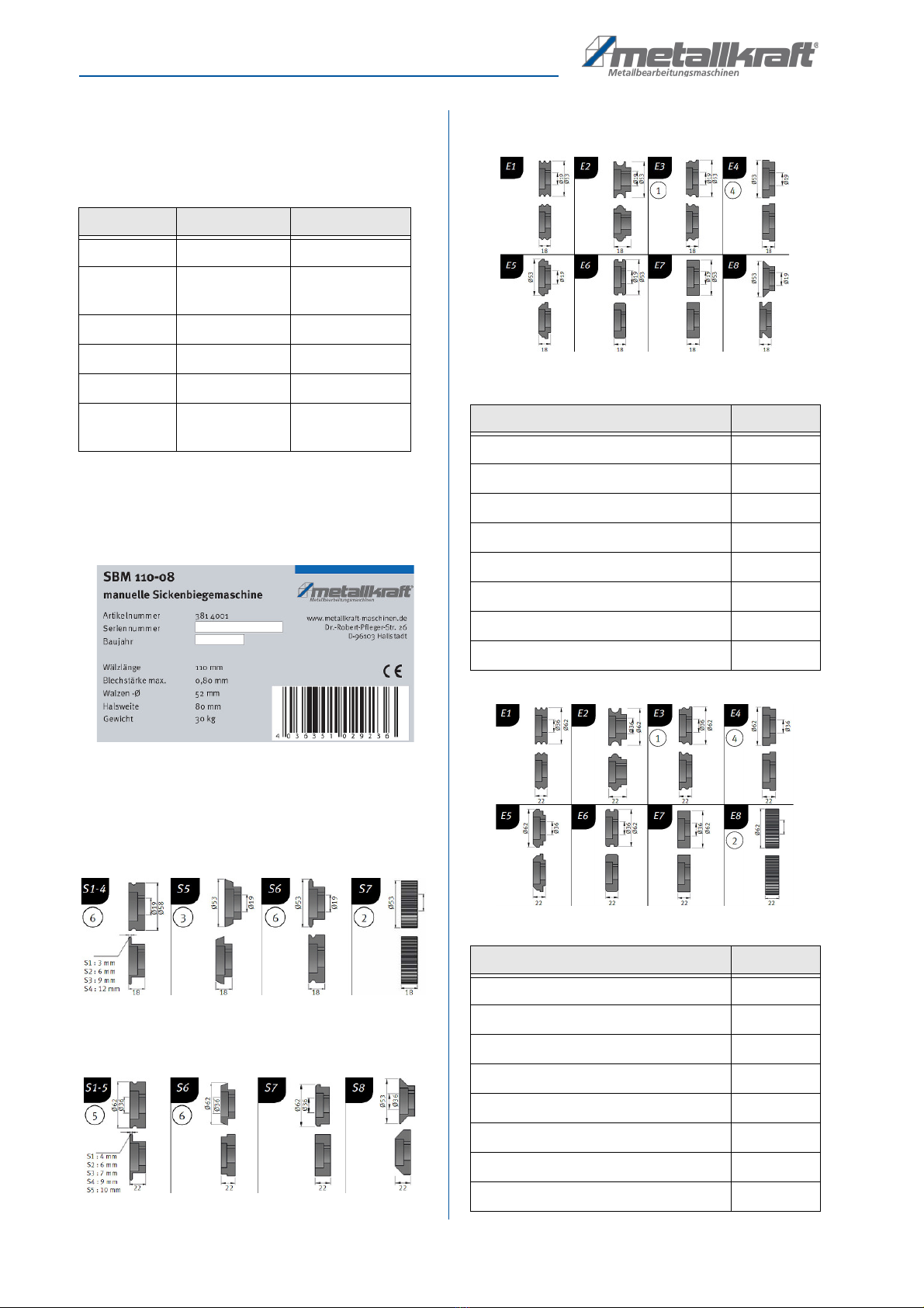
4.3 Scope of delivery
SBM 110-08
Fig. 3: Standard rollers
SBM 140-12
Fig. 4: Standard rollers
4.4 Accessories (not included)
Fig. 5: Accessories rollers for SBM 110-08
Fig. 6: Accessories rollers for SBM 140-12
Model SBM 110-08 SBM 140-12
Roller length 110 mm 140 mm
Max. sheet
thickness*
0,80 mm 1,2 mm
Roller Ø 52 mm 62 mm
Collar width 80 mm 100 mm
Weight 30 kg 50 kg
Dimensions
L x W x H
380 x180 x 380
mm
560 x 220 x 500
mm
Description Art. Nr.
Bending rollers type E1 3880121
Bending rollers type E2 3880122
Bending rollers type E3 3880123
Bending rollers type E4 3880124
Bending rollers type E5 3880125
Bending rollers type E6 3880126
Bending rollers type E7 3880127
Bending rollers type E8 3880128
Description Item. Nr.
Bending rollers type E1 3880131
Bending rollers type E2 3880132
Bending rollers type E3 3880133
Bending rollers type E4 3880134
Bending rollers type E5 3880135
Bending rollers type E6 3880136
Bending rollers type E7 3880137
Bending rollers type E8 3880138

ransport, packaging and storage
SBM-Series | Version 2.02 9
5 Transport, packaging and storage
5.1 Delivery and transport
5.1.1 Delivery
After delivery, check the bead bending machine for vi-
sible transport damage. If the bead bending machine
shows any damage, this must be reported immediately
to the transport company or the dealer.
All packaging must be removed; the corresponding in-
structions in this operating manual for installation must
be read. Possible transport damage must be immedi-
ately documented photographically for the purpose of in-
surance benefits.
To avoid accidents, the necessary precautions must be
taken when unloading and transporting the machine.
See the chapter on safe handling of this machine.
5.1.2 Transport
5.2 Packaging
All packaging materials and packaging aids used in the
machine are recyclable and must always be recycled.
Cardboard packaging components must be shredded for
collection of waste paper.
The foils are made of polyethylene (PE) and the uphol-
stery parts made of polystyrene (PS). These substances
must be handed over to a recycling center or to the re-
sponsible disposal company.
5.3 Storage
The bead bending machine must be thoroughly cleaned
before it is stored in a dry, clean and frost-free environ-
ment.
5.4 Placement
In order to achieve good functionality and a long service
life of the bead bending machine, the installation site
should meet the following criteria:
- The underground must be even, solid and vibration-
free.
- The machine should be firmly anchored to ensure a
safe stand.
- There must be sufficient space for the operating per-
sonnel, for material transport and for adjustment and
maintenance work.
A EN ION!
When transporting and lifting the bead bending
machine make sure that the transport and lifting
equipment can support the load.
WARNING!
Risk of fatal injury!
If the weight of the machine and the permissible load
capacity of the lifting equipment are not observed
during transport or lifting work, the machine may tip
over or fall.
Use protective gloves!
Wear safety boots!
CAU ION!
Danger of crushing!
The bead bending machine can tilt during installation
and lead to serious injuries.
10 SBM-Series | Version 2.02
Description of device
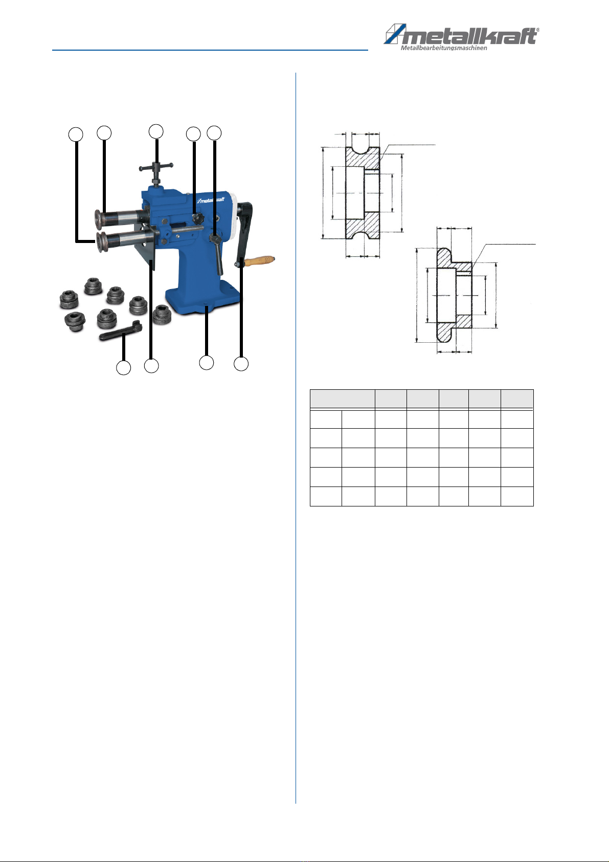
6 Description of device
Operating elements
Fig. 7: Description SBM 140-12
1. Bending roller (right-hand thread)
2. Bending roller (left hand thread)
3. Height adjustment
4. Locking screw
5. Lever „longitudinal adjustment“
6. Drive lever of the bending rolls
7. Anchoring boring hole
8. Stop plate
9. Tool for changing the rollers
7 Description of the roller sets
7.1 Roller set S1 to S5
Fig. 8: Dimensions of rollers S1-S5
The dimensions of the standard bending roller sets are li-
sted in the table. This means S1 for roller set 1, S2 for
roller set 2, etc.
12
876
5
4
3
9
Description S1 S2 S3 S4 S5
A mm 3 3,5 4 4 4
B mm 6,4 8,4 9,4 11,4 12,4
C mm 12,6 10,1 8,6 6,6 5,6
D mm 4 6 7 9 10
E mm 18 16 15 13 12
3x6 Feather key groove
3x6
A B C
Ø 62
Ø 43
Ø 26
Ø 36
Ø 53
Ø 26
Ø 36
Ø 62
12 10
DE
12 10
Feather key grove

Replacing the rollers
SBM-Series | Version 2.02 11
7.2 Roller set S6
Fig. 9: Dimensions of roller set S6
7.3 Roller set S7
Fig. 10: Dimensions of roller set S7
7.4 Roller set S8
Fig. 11: Dimensions of roller set S8
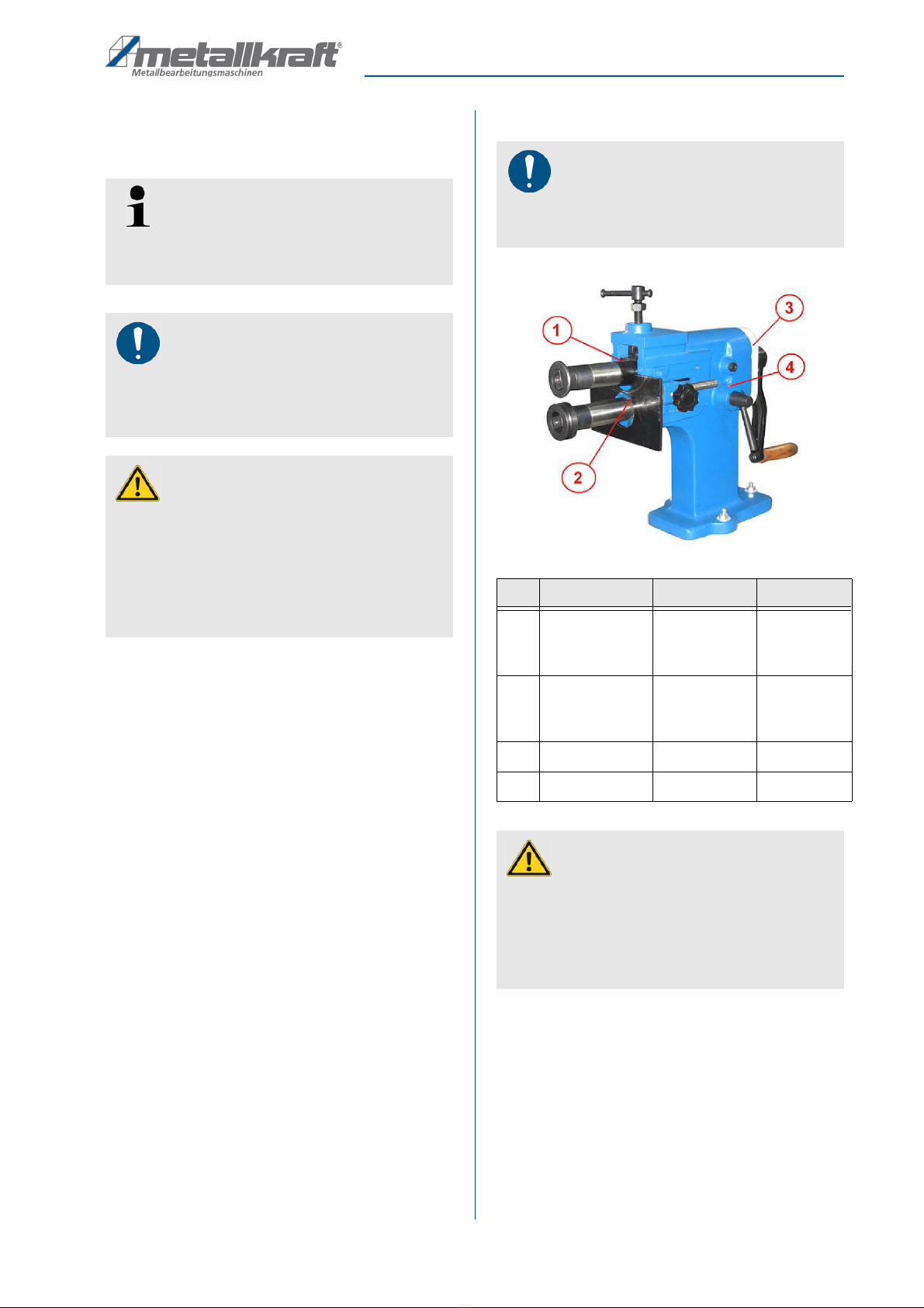
8 Replacing the rollers
Step 1: Move the upper drive shaft a little upwards using
the toggle screw so that the rollers are free and
can be removed.
Step 2: Open the two fixing nuts from the bending rollers.
Use the special key provided for this purpose.
Step 3: Pull off the two rollers and mount the the ones
they want..
3x6 Feather key grove
3x6
22
616
Ø 26
Ø 26
Ø 43
10
12
Ø 62
Ø 55
Ø 38
6 16
1,5
12 10
Ø 62
Ø 58
Ø 38
Feather key grove
3x6 Feather key grove
3x6
22
Ø 62
Ø 36
Ø 26
12 10 913
12 10
Ø 36
Ø 49
Ø 62
Ø 43
Ø 26
Feather key grove
A EN ION!
The thread on the upper roller is a right-hand thread
and the thread on the lower roller is a left-hand
thread.
A EN ION!
To prevent the upper and lower rollers from being
interchanged, the shaft diameters are different.
3x6 Feather key grove
3x6
814
Ø 43
Ø 38
Ø 62
Ø 48
Ø 43
Ø 38
Ø 62
Ø 26
Ø 26
12 10
8410
12 10
Feather key grove

12 SBM-Series | Version 2.02
Working with the bead bending machine
Step 4: Tighten the two nuts after mounting the bending
rolls.
Step 5: Then pull the rollers to the middle. To do this,
open the locking screw of the longitudinal adjust-
ment and adjust the rollers to the middle using
the lever on the opposite side.
Fig. 12: Replacing the rollers
9 Working with the bead bending ma-
chine
Step 1: First of all, the required bending rollers must be
mounted. The upper bending roll is secured by a
nut with right-hand thread, the lower bending roll
by a nut with left-hand thread. These two nuts
must be tightened securely after the assembly of
the bending rolls to guarantee safe working!
Step 2: To adjust the parallelism of the bending rolls, loo-
sen the locking screw on the left side and adjust
the length of the lower shaft using the lever on
the right side. After you have aligned the bending
rollers, fix the shaft by tightening the locking
screw on the left side again.
Step 3: Now adjust the stop plate by loosening the two
locking screws on the left and right and moving
the stop plate by hand to the desired dimension.
Then fix the stop plate again with the two locking
screws.
Step 4: Set the maximum infeed by adjusting the upper
shaft to the desired dimension using the height
adjustment/infeed lever and turning the nut down
to the stop.
Step 5: Use the height adjustment lever to move the up-
per shaft upwards until the material fits between
the bending rolls. Push the material up to the
stop plate.
Step 6: Now turn the upper shaft down to the stop screw
(set in step 4).
Step 7: Move the lever to drive the shafts / rollers in the
desired direction and shape your sheet metal.
If it is not possible to the complete infeed in one pass due
to high material thickness, this is also possible in several
partial steps. Repeat steps 6 to 7 until the desired infeed
depth/forming is reached.
Left-hand
Stop plate
Locking screw for
longitudinal adjust-
Locking screw for
stop plate
Right-hand
thread
thread
Height adjust-
ment/ Upper roller
Lever for longitudinal adju-
stment of the lower drive
Special key for changing
the rollers
Care, maintenance and repair/ servicing
SBM-Series | Version 2.02 13
10 Care, maintenance and repair/
servicing
After maintenance, repair and cleaning work, check that
all covers and protective devices have been properly fit-
ted to the bead bending machine and that no tools are
left inside or in the working area of the bead bending ma-
chine
10.1 Care by cleaning
Clean the bead bending machine regularly with a soft,
damp cloth.
10.2 Lubrication schedule
Fig. 13: Lubrication points
The bead bending machine must be lubricated regularly at the points
marked in Fig.13 according to the table. If the service life of the machine
is more than 8 hours per day, it must be lubricated more often.
Note that some of the lubrication points are located in the machine
housing (2 and 3). You may need to remove the covers to get to these
points.
ips and recommendations
Proper and correct maintenance is a prerequisite for
maximum service life, good working conditions and
machine productivity.
NO E!
The maintenance instructions must be read carefully
before care and maintenance of the bead bending
machine. Only persons familiar with the bead ben-
ding machine are permitted to use it
DANGER!
Danger if insufficient qualification
of persons!
Insufficiently qualified persons cannot assess the
risks associated with maintenance work on the
machine and expose themselves and other persons
to the risk of serious injury.
- Have all maintenance work carried out by qualified
personnel only.
NO E!
The bead bending machine must be lubricated at
regular intervals to ensure efficient operation and a
long service life of the machine.
No. Location Interval Lubricant
1 Lubrication
bore of the up-
per shaft
Once a week rease
2 Lubrication
bore of the
lower shaft
Once a week rease
3 earbox Once a week rease
4 earbox Once a week rease
A EN ION!
The bending rollers of the bead bending machine
must never be lubricated or oiled, as otherwise the
material could slip through and is not bent. Always
keep the bending rolls free of oil and grease. Also
make sure that the material to be bent is free of oil,
grease and dirt.

14 SBM-Series | Version 2.02
roubleshooting
11 Troubleshooting
12 Disposal, recycling of old equipment
In your own interests and in the interest of the environ-
ment, please ensure that all components of the machine
are disposed of in the proper and approved way.
12.1 Decommission
Disused equipment must be taken out of service immedi-
ately in order to avoid later misuse and endangering the
environment or people.
Step 1: Remove all environmentally hazardous fluids
from the old unit.
Step 2: If necessary, dismantle the machine into mana-
geable and usable assemblies and compo-
nents.
Step 3: uide the machine components and operating
materials to the appropriate disposal routes.
12.2 Disposal of new equipment packaging
All packaging materials and packaging aids used in the
machine are recyclable and must always be recycled.
The packaging wood can be disposed of or recycled.
Cardboard packaging components can be crushed and
sent for waste paper collection.
The films are made of polyethylene (PE) or padded parts
of polystyrene (PS). These materials can be reused after
processing if they are passed on to a recycling collection
point or to the disposal company responsible for them.
Only pass on the packaging material sorted by type so
that it can be directly recycled.
12.3 Disposal of the old device
Electrical equipment contains a variety of recyclable ma-
terials and environmentally harmful components.
These components must be disposed of separately and
properly. In case of doubt, contact the municipal waste
disposal department.
If necessary, a specialist waste disposal company
should be called upon to help with processing.
12.4 Disposal of lubricants
The disposal instructions for the lubricants used are pro-
vided by the lubricant manufacturer. If necessary, ask for
the product-specific data sheets.
A EN ION!
If one of the following errors occurs, stop working
with the machine immediately. Serious injury could
result. All repairs and replacement work may only be
carried out by qualified and trained personnel.
Fault Possible cause Solution
The bead
bending ma-
chine does
not work.
1. The mechani-
cal system is
defective.
1. Check the
mechanics.
2. Contact the
dealer/manu-
facturer.
The bead
bending ma-
chine does
not bend the
material cor-
rectly.
1. The material
thickness
could be
wrong.
2. The wrong
material has
been used.
1. Observe max.
sheet thick-
ness.
2. insert only the
correct mate-
rial.
The machine
does not
bend the ma-
terials as indi-
cated in the
catalogue.
1. The material
thickness
could be
wrong.
2. The mecha-
nics are faulty.
1. Check the
bending ma-
terial.
2. Contact the
dealer/manu-
facturer.
A EN ION!
Please ensure that the coolants and lubricants used
are disposed of in an environmentally friendly man-
ner. Observe the disposal instructions of your local
waste disposal company.
NO E
Used cooling lubricant emulsions and oils should not
be mixed, as only unmixed waste oils can be used
without pre-treatment.

Spare parts
SBM-Series | Version 2.02 15
12.5 Disposal via municipal collection points
Disposal of used electrical and electronic equipment (to
be used in the countries of the European Union and
other European countries with a separate collection sy-
stem for this equipment)
The symbol on the product or its packaging
indicates that this product is not to be dispo-
sed of as normal household waste, but must
be returned to a collection point for the recy-
cling of electrical and electronic equipment.
By contributing to the correct disposal of this
product, you protect the environment and the health of
your fellow human beings. Environment and health are
endangered by incorrect disposal. Material recycling
helps to reduce the consumption of raw materials. For
more information about recycling this product, contact
your local community, municipal waste management
company or the store where you purchased the product.
13 Spare parts
13.1 Spare parts order
The spare parts can be obtained from the dealer or di-
rectly from the manufacturer. The contact details are in
chapter 1.2 Customer Service.
Specify the following key data for inquiries or when orde-
ring spare parts:
- machine type
- item number
- position number
- construction year
- amount
- desired shipping method (post, freight, sea, air, ex-
press)
- delivery address
Spare parts orders without above given information can
not be considered. If the shipping method is missing,
shipping will be at the discretion of the supplier.
Information on the machine type, article number and
year of manufacture can be found on the nameplate,
which is attached to the machine.
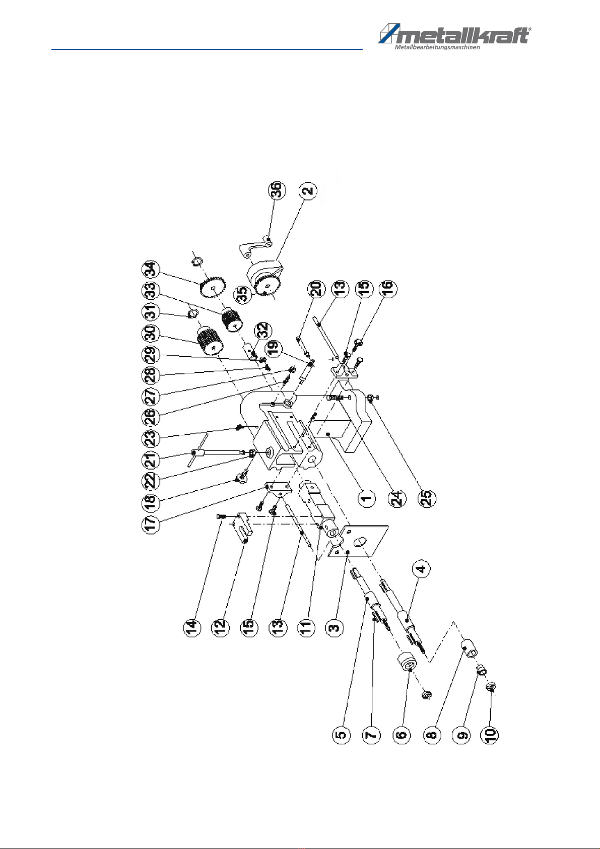
Example
The Crank handle for the Bead Bending Machine SBM
110-08 must be ordered. The Crank handle has the num-
ber 36 in the spare parts drawing 1.
By ordering spare parts, send a copy of the spare parts
drawing (1) with the marked part (Crank handle) and
marked positon number (36) to the dealer or spare parts
department and provide the following information:
- Type of machine: Bead Bending Machine
SBM 110-08
- Item number: 3814001
- Drawing number: 1
- Position number: 36
he item number of your machine:
Bead Bending Machine SBM 140-12: 3814002
Bead Bending Machine SBM 110-08: 3814001
DANGER!
Risk of injury by using wrong spare
parts!
Dangers may result for the user and damages as well
as malfunctions may be caused by using wrong or
damaged spare parts.
- Only use original spare parts of the manufacturer or
spare parts admitted by the manufacturer.
- Always contact the manufacturer in case of uncer-
tainties.
NO E!
Loss of warranty!
The manufacturer's warranty will become null and
void if non admitted spare parts are being used.
16 SBM-Series | Version 2.02
Spare parts
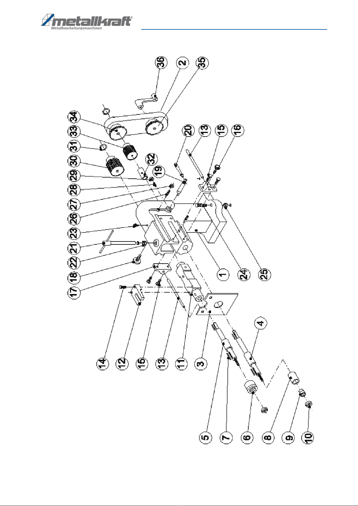
13.2 Spare parts drawings
The following drawings should help to identify necessary spare parts in case of service. To order, send a copy of the parts
drawing with the marked components to your authorized dealer.
13.2.1Spare parts drawing SBM 110-08
Fig. 14: Spare parts drawing SBM 110-08
Spare parts
SBM-Series | Version 2.02 17
13.2.2Spare parts drawing SBM 140-12
Fig. 15: Spare parts drawing SBM 140-12

www.metallkraft.de
This manual suits for next models
3
Table of contents
Other Metallkraft Lathe manuals


