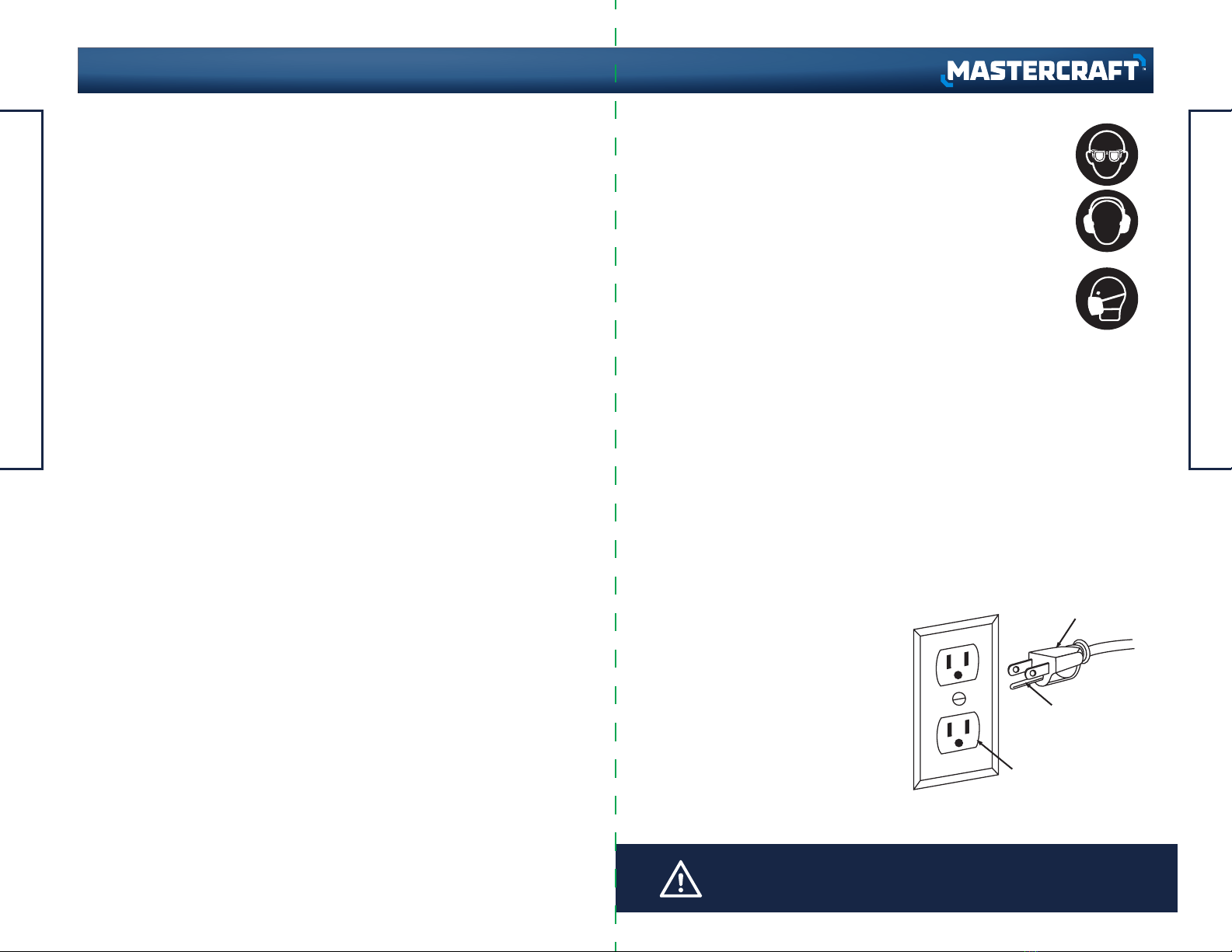
manuals.online logo
Brands
  1. Home
  2. •
  3. Brands
  4. •
  5. MasterCraft
  6. •
  7. Lathe
  8. •
  9. MasterCraft 055-6793-6 User manual

MasterCraft 055-6793-6 User manual

Other MasterCraft Lathe manuals

MasterCraft 055-4504-8 User manual

MasterCraft

MasterCraft 055-4504-8 User manual

MasterCraft 55-4504-8 User manual

MasterCraft

MasterCraft 55-4504-8 User manual

Popular Lathe manuals by other brands

Holzmann VD 1100ECO user manual

Holzmann

Holzmann VD 1100ECO user manual

Grizzly G0632 Parts Breakdown

Grizzly

Grizzly G0632 Parts Breakdown

Grizzly G0462 owner's manual

Grizzly

Grizzly G0462 owner's manual

Grizzly G0709 owner's manual

Grizzly

Grizzly G0709 owner's manual

Grizzly G0949G owner's manual

Grizzly

Grizzly G0949G owner's manual

Kval 990-H Service manual

Kval

Kval 990-H Service manual

Teknatool Nova Mercury operating manual

Teknatool

Teknatool Nova Mercury operating manual

Traub TNL12.2 operating instructions

Traub

Traub TNL12.2 operating instructions

WoodFast M305 instruction manual

WoodFast

WoodFast M305 instruction manual

Milltronics ML Series Instruction handbook

Milltronics

Milltronics ML Series Instruction handbook

Milltronics SL6 Series Instruction handbook

Milltronics

Milltronics SL6 Series Instruction handbook

OmniTurn GT-75 user manual

OmniTurn

OmniTurn GT-75 user manual

Axminster CQ6230A-2/910 user manual

Axminster

Axminster CQ6230A-2/910 user manual

Jet JWL-1640EVS Operating instructions and parts manual

Jet

Jet JWL-1640EVS Operating instructions and parts manual

Grizzly G4000 owner's manual

Grizzly

Grizzly G4000 owner's manual

HOLZMANN MASCHINEN ED1000FB user manual

HOLZMANN MASCHINEN

HOLZMANN MASCHINEN ED1000FB user manual

Hercus 260 Maintenance manual

Hercus

Hercus 260 Maintenance manual

Optimum OPTIturn TM 3310 operating manual

Optimum

Optimum OPTIturn TM 3310 operating manual

manuals.online logo
manuals.online logoBrands
  • About & Mission
  • Contact us
  • Privacy Policy
  • Terms and Conditions

Copyright 2025 Manuals.Online. All Rights Reserved.

IMPORTANT:
Please read this manual carefully before running this
wood lathe and save it for reference.
INSTRUCTION
MANUAL
WOOD LATHE
model no. 055-6793-6
headline bars
continuation tabs
notes
warnings
3
headline bars
continuation tabs
notes
warnings
TABLE OF CONTENTS
TABLE OF CONTENTS
headline bars
continuation tabs
notes
warnings
headline bars
continuation tabs
notes
warnings
model no. 055-6793-6 | contact us 1-800-689-9928
NOTE:
If any parts are missing or damaged, or if you have any questions, please call our
toll-free helpline at 1-800-689-9928.
SAVE THESE INSTRUCTIONS
This manual contains important safety and operating instructions.
Read all instructions and follow them when using this product.
TABLE OF CONTENTS
Quick Start Guide
Specifications
Safety Guidelines
Know Your Wood Lathe
Assembly Instructions
Operating Instructions
Maintenance
Troubleshooting
Exploded View
Parts List
Warranty
4
5
6
12
15
21
24
25
26
27
28
(1) • Place the wrench (2) over the
flats on the faceplate.
• Insert the tip of the push-out rod
(3) into one of the slots in the
side of the headstock spindle.
see page 19
(2) The On/Off switch (2) controls
application of electrical power to
the lathe’s motor. The safety key
(3) must be placed in the switch
before the switch will operate.
see page 22
2
3
3
2
5
SPECIFICATIONS
4
QUICK START GUIDE
headline bars
continuation tabs
notes
warnings
headline bars
continuation tabs
notes
warnings
model no. 055-6793-6 | contact us 1-800-689-9928
SPECIFICATIONS
Motor
Speeds
Distance between centres
Swing-over bed
Drive spindle
Tailstock spindle travel
Headstock/tailstock internal taper
Weight
120 V AC, 60 Hz, 3.3 A
500–3500 RPM
13" (33 cm)
8" (20.3 cm)
1 1/4" (3.2 cm), 8 TPI thread
2" (5 cm)
No. 2 MT
55 lb (25 kg)
SAFETY GUIDELINES
This manual contains information that relates to PROTECTING PERSONAL SAFETY
and PREVENTING EQUIPMENT PROBLEMS. It is very important to read this manual
carefully and understand it thoroughly before using the product. The symbols listed
below are used to indicate this information.
DANGER!
Potential hazard that will result in serious injury or loss of life.
WARNING!
Potential hazard that could result in serious injury or loss of life.
CAUTION!
Potential hazard that may result in moderate injury or damage to
equipment.
Note: The word “Note” is used to inform the reader of something the operator needs
to know about the tool.
SAFETY RECOMMENDATIONS
These precautions are intended for the personal safety of the operator and others
working with the operator.
Failure to follow these instructions may result in a permanent loss of vision, serious
personal or even fatal injury, property damage and/or tool damage. Please take time
to read and understand them.
Safety is a combination of common sense, staying alert, and knowing how your
wood lathe works.
BEFORE USE
•READ and become familiar with this entire instruction manual. Learn the tool’s
applications, limitations, and possible hazards.
•AVOID DANGEROUS CONDITIONS. DO NOT use power tools in wet or damp areas,
and DO NOT expose them to rain. Keep work areas well lit.
•DO NOT use power tools in the presence of flammable liquids or gases.
•ALWAYS keep your work area clean, uncluttered and well lit. DO NOT work on
floor surfaces that are slippery with sawdust or wax.
•KEEP BYSTANDERS AT A SAFE DISTANCE FROM the work area, especially when
the tool is operating. NEVER allow children or pets near the tool.
•DON'T FORCE TOOL. It will do the job better and safer at the rate for which it was
designed.
•USE RIGHT TOOL. Don't force tool or attachment to do a job for which it was not
designed.
•DRESS FOR SAFETY. DO NOT wear loose clothing, gloves, neckties, or jewellery
(rings, watches) when operating the tool. Inappropriate clothing and items can
get caught in moving parts and pull you in. ALWAYS wear non-slip footwear, and
tie back long hair.
•WEAR A FACE MASK OR DUST MASK. The lathe operation produces dust.
•ALWAYS remove the power cord plug from the electric outlet when making
adjustments, changing parts, cleaning, or working on the tool.
•KEEP GUARDS IN PLACE AND IN WORKING ORDER.
•AVOID ACCIDENTAL START-UPS. Make sure the power switch is in the Off
position before plugging in the power cord.
•REMOVE ADJUSTMENT TOOLS. ALWAYS MAKE SURE all adjustment tools are
removed from the lathe before turning it on.
•NEVER LEAVE A RUNNING TOOL UNATTENDED. Turn the power switch to the Off
position. DO NOT leave the tool until it has come to a complete stop.
•NEVER STAND ON THE TOOL. Serious injury could result if the tool tips or is
accidentally hit. DO NOT store anything above or near the tool.
•DO NOT OVERREACH. Keep proper footing and balance at all times. Wear
oil-resistant, rubber-soled footwear. Keep floor clear of oil, scraps, and other
debris.
•MAINTAIN TOOLS PROPERLY. ALWAYS keep tools clean and in good working
order. Follow instructions for lubricating and changing accessories.
•CHECK FOR DAMAGED PARTS. Check for alignment of moving parts, jamming,
breakage or any other conditions that may affect the tool’s operation. Any part
that is damaged should be properly repaired or replaced before use.
•MAKE WORKSHOP CHILDPROOF. Use padlocks and master switches, and
ALWAYS remove the starter keys.
•DO NOT operate tool if you are under the influence of drugs, alcohol or
medication that could affect your ability to use the tool properly.
SPECIFIC SAFETY RULES FOR THE WOOD LATHE
•DO not operate the lathe until it is completely assembled and installed
according to the instructions.
•FOR YOUR OWN SAFETY, read the entire instruction manual before operating the
lathe.
WARNING!
To avoid mistakes that could cause serious injury, do not plug in the wood lathe until
you have read and understood the following rules.
SAFETY GUIDELINES
7
6
SAFETY GUIDELINES
headline bars
continuation tabs
notes
warnings
headline bars
continuation tabs
notes
warnings
model no. 055-6793-6 | contact us 1-800-689-9928
Three-prong plug
Grounding prong
Properly grounded outlet
FPO
FPO
Fig. 1
USE SAFETY GOGGLES AND EAR PROTECTION:
ALWAYS WEAR EYE PROTECTION THAT CONFORMS WITH CUL
REQUIREMENTS. FLYING DEBRIS can cause permanent eye damage.
The tool is loud and the sound can cause hearing damage. Always
wear ear protection to help prevent hearing damage and loss. Failure
to comply may result in moderate injury.
USE DUST MASK:
Some dust created by sawing contains chemicals that are known to
cause cancer, birth defects or other reproductive harm. Some examples
of these chemicals come from lead-based paints; crystalline silica from
bricks, cement and other masonry products; and arsenic and chromium from
chemically treated lumber. To reduce exposure to these chemicals, work in a
well-ventilated area with approved safety equipment, such as dust masks that are
specially designed to filter out microscopic particles.
ELECTRICAL SAFETY
GROUNDING INSTRUCTIONS:
In the event of a malfunction or breakdown, grounding provides a path of least
resistance for electric current to reduce the risk of electric shock. This tool is
equipped with an electric cord having an equipment-grounding conductor and a
grounding plug. The plug must be plugged into a matching outlet that is properly
installed and grounded in accordance with all local codes and ordinances.
Do not modify the plug provided. If it will not fit the outlet, have the proper outlet
installed by a qualified electrician.
Improper connection of the
equipment-grounding conductor
can result in a risk of electric shock. The
conductor with a green outer surface,
with or without yellow stripes, is the
equipment-grounding conductor. If repair
or replacement of the electric cord or
plug is necessary, do not connect the
equipment-grounding conductor to a live
terminal.
CAUTION!
In all cases, verify that the outlet in question is properly grounded. if you are not sure,
have a licensed electrician check the outlet.
•ALWAYS WEAR eye protection.
•DO NOT wear gloves, necktie or loose clothing.
•TIGHTEN all locks before operating.
•DO NOT mount a split workpiece.
•USE the lowest speed when starting a new workpiece.
•READ the warning label attached to the lathe.
•WHEN TURNING A WORKPIECE, always rough the wood to round form at slow
speed. If the lathe vibrates when running, there is a risk that the workpiece will
be thrown or the tool jerked from your hands.
•ALWAYS ROTATE the workpiece by hand before turning on the motor. If the
workpiece strikes the tool rest, it could split and be thrown out of the lathe.
•DO NOT allow the turning tools to bite into the wood. The wood could split or be
thrown from the lathe.
•ALWAYS POSITION the tool rest above the centreline of the lathe when shaping
a piece of stock.
•DO NOT operate the lathe if it is rotating in the wrong direction. The workpiece
must always be rotating toward you.
•BEFORE ATTACHING a workpiece to the faceplate, always rough it out to make
it as rough as possible. This minimizes vibrations while the piece is being
turned. Always fasten the workpiece securely to the faceplate. Failure to do so
could result in the workpiece being thrown from the lathe.
•POSITION your hands so that they will not slip onto the workpiece.
•REMOVE all loose knots in the stock before mounting it between the centres or
on the faceplate.
•DO NOT LEAVE A RUNNING LATHE UNATTENDED. Leave the work area only after
the motor has come to a full stop.
•HANG your turning tools on the wall beyond the tailstock end of the lathe. Do not
lay them on the bench so that you must reach over the revolving workpiece to
select them.
•KEEP A FIRM HOLD and remain in control of the cutting tool at all times. Take
special precautions when shaping a section of stock in which knots or voids
are found.
•COMPLETE the hand-sanding of all workpieces before removing them from the
lathe.
•DISCONNECT TOOLS before servicing and when changing accessories, such
as blades, bits, cutters, and the like.
SAFETY GUIDELINES
9
8
SAFETY GUIDELINES
headline bars
continuation tabs
notes
warnings
headline bars
continuation tabs
notes
warnings
model no. 055-6793-6 | contact us 1-800-689-9928
FPO
Check with a qualified electrician or service technician if the grounding instructions
are not completely understood, or if in doubt as to whether the tool is properly
grounded. Use only three-wire extension cords that have three-prong grounding
plugs and three-pole receptacles that accept the tool's plug, as shown in Fig. 1.
Repair or replace a damaged or worn cord immediately.
AMPERAGE RATING
OF THE TOOL
(120 V CIRCUIT ONLY)
MORE
THAN
0
6
10
12
NOT MORE
THAN
6
10
12
16
25'
(7.6 m)
18
18
16
14
50'
(15.2 m)
16
16
16
12
100'
(30.5 m)
16
14
14
Not recommended
150'
(45.7 m)
14
12
12
TOTAL LENGTH OF THE EXTENSION CORD
MINIMUM GAUGE FOR
THE EXTENSION CORD (AWG)
Recommended size for extension cords
USING EXTENSION CORD:
•Make sure the extension cord is in good condition. When using an extension cord,
be sure to use one that is heavy enough to carry the current that your product
will draw. An undersized cord will cause a drop in line voltage, which will result
in loss of power and overheating. The table on the next page shows the correct
size to be used according to cord length and nameplate ampere rating. When in
doubt, use the next heavier gauge. The smaller the gauge number, the heavier
the cord.
•Make sure your extension cord is properly wired and in good condition. Always
replace a damaged extension cord, or have it repaired by a qualified person
before using it. Protect your extension cords from sharp objects, excessive heat,
and damp or wet areas.
•Use a separate electrical circuit for your tools. This circuit must consist of not less
than #12 wire with a 20 A time-delayed fuse or #14 wire with a 15 A
time-delayed fuse. Before connecting the motor to the power line, make sure
the switch is in the OFF position and the electric current is rated the same as the
current stamped on the motor nameplate. Running at a lower voltage will
damage the motor.
WARNING!
• Use the proper extension cord. Make sure to use an extension cord that is heavy
enough to carry the current required by the tool. An undersized cord will cause a
drop in line voltage, resulting in loss of power and overheating of the tool.
• Use the extension cord only for intended purposes. Do not pull the extension cord to
remove it from the power socket.
WARNING!
This tool must be grounded while in use in order to protect the operator from electric
shock.
NOTE:
Recycle unwanted materials rather than disposing of them as
waste. Sort the tool and its components in specific categories
and take to the local recycling centre or dispose of them in an
environmentally safe way.
SAFETY GUIDELINES
11
10
SAFETY GUIDELINES
headline bars
continuation tabs
notes
warnings
headline bars
continuation tabs
notes
warnings
model no. 055-6793-6 | contact us 1-800-689-9928
No.
1
2
3
4
5
6
7
8
9
10
11
12
13
14
15
16
17
18
19
20
21
22
23
24
Description
7" Tool rest
Tailstock cup centre
Hand wheel
Reset button
Safety key
Faceplate
Tool caddy
Push-out rod
8 mm Hex key
5 mm Hex key
4 mm Hex key
4.5" Tool rest
Wrench storage
Flat wrench
Tailstock lock lever
Spindle lock lever
Tool rest lock lever
Tool rest base
Headstock spur centre
On/Off switch
Speed control knob
Base lock lever
Motor
Headstock
23
12 9101113
22 2021
21
3
5
6
8
7
4
18 1917
15
14
16
24
ON/OFF switch:
This wood lathe has an easy-access power switch located on the right side of the
machine. To lock the switch in the off position, remove the switch key from the
switch. Place the key in a location that is inaccessible to children and others not
qualified to use the tool.
Chuck:
A clamping device for holding work in the lathe or for holding drills in the tailstock.
1312
KNOW YOUR WOOD LATHE
headline bars
continuation tabs
notes
warnings
headline bars
continuation tabs
notes
warnings
model no. 055-6793-6 | contact us 1-800-689-9928
FPO
PACKAGE CONTENTS
NO. Description Qty. Illustration
Wood lathe assembly
7" Tool rest
4 1/2" Tool rest
Faceplate
Push-out rod
Headstock spur centre
Tailstock cup centre
Wrench
1
2
3
4
5
6
7
8
1
1
1
1
1
1
1
1
Between centres:
A dimension representing the maximum length of a workpiece that can be turned
between centres. Also a method of holding a workpiece by mounting it between the
centres of the headstock and the tailstock spindles.
Centre:
A precision-ground tapered cylinder with a pointed tip and a morse taper shaft. Used
in the tailstock to support the end of long workpieces. May also be used in the
headstock spindle to support work between centres at both ends.
Centreline:
An imaginary line extending from the centre of the spindle through the centre of the
tailstock ram, representing the central axis of the lathe around which the work
rotates.
Morse taper (MT):
A taper of specific dimensions used to mate matching male and female parts
together tightly. The tailstock has a MT-2 Morse taper.
Bed:
Main supporting casting running the length of the lathe.
Tool rest base:
Movable platform where the tool rest is mounted. It can be set at an angle to the
workpiece (also known as compound slide and compound rest).
Faceplate:
A metal plate with a flat face-mounted spindle to hold irregularly shaped work.
Headstock:
The main casting mounted on the left end of the bed where the spindle is mounted.
Houses the spindle gears.
Tailstock:
Assembly that slides along the bed and can be locked in place. Used to hold long
workpieces in place or to mount a drill chuck.
Hand wheel:
Moves the tailstock in and out.
Tool rest:
A device mounted on the compound that holds the cutting tool.
Tailstock lock lever:
Locks the tailstock in position. Unlock handle to position the tool rest in any location
along lathe bed. Tighten lever when properly positioned.
ASSEMBLY INSTRUCTIONS
1514
KNOW YOUR WOOD LATHE
headline bars
continuation tabs
notes
warnings
headline bars
continuation tabs
notes
warnings
model no. 055-6793-6 | contact us 1-800-689-9928
FPO
FPO
TOOLS NEEDED FOR ASSEMBLY
Screwdriver Wrench
NO. Description Qty. Illustration
4, 5, 8 mm hex keys
M10 x 40 Hexagon socket bolts,
Flat washers 10 and spring
washers 10
9
10
3
4
Fig. 2
24 3/8" (62 cm)
25 5/8" (65 cm)
5 1/2"
(14 cm)
5 1/2"
(10.5 cm)
CAUTION!
The wood lathe is heavy and must be lifted with the help of another person.
WARNING!
If any parts are damaged or missing, do not operate this tool until the parts are
replaced. Use of this product with damaged or missing parts could result in serious
personal injury.
• Do not attempt to modify this tool or create accessories not recommended for use
with this tool. Any such alteration or modification is misuse and could result in a
hazardous condition leading to possible serious personal injury.
• Do not connect to power supply until assembly is complete. Failure to comply could
result in accidental starting and possible serious personal injury.
• Risk of injury! Always pull out the mains plug (disconnect the product from its power
supply) before commencing work on the product.
WARNING!
The lathe must be bolted to a bench top. Operating a lathe that is not bolted down may
result in serious injury.
NOTE:
To hold the lathe securely, the bolts must engage a minimum of
1" (2.5 cm) into the frame.
UNPACKING
Do not use this product if any parts of the package contents are already assembled to
your product when you unpack it. Package contents are not assembled to the product
by the manufacturer and require customer installation. Use of a product that may
have been improperly assembled could result in serious personal injury.
• Inspect the tool carefully to make sure no breakage or damage occurred during
shipping.
• Do not discard the packing material until you have carefully inspected and satisfactorily
operated the tool.
• If any parts are damaged or missing, please call: 1-800-689-9928 for assistance.
MOUNTING THE LATHE ON A BENCH TOP (Fig. 2)
• In a clear space on the bench top, measure and mark four hole centres as shown
in Fig. 2.
• Drill clearance holes through the bench top. Position the lathe on the bench top.
• Install the M10 x 40 hexagon socket bolts with flat washers 10 and spring washer
10 (included in the hardware bag) from underneath the bench top into the tapped
holes in the bottom of the lathe frame.
ASSEMBLY INSTRUCTIONS
17
16
ASSEMBLY INSTRUCTIONS
headline bars
continuation tabs
notes
warnings
headline bars
continuation tabs
notes
warnings
model no. 055-6793-6 | contact us 1-800-689-9928
FPO
3
2
1
13
2 1
Fig. 3
Fig. 4
Fig. 5 Fig. 6
Fig. 7
12
3
WARNING!
Do not operate the lathe until it is completely assembled and adjusted according to the
instructions.
NOTE:
The spring-loaded handles on the lathe are designed to minimize
interference with other lathe parts or the workpiece. To operate,
push the handle lever in and turn clockwise to tighten. Pulling
the handle lever outward will disengage the threaded shaft,
allowing you to reposition the lever handle so it is out of the way.
NOTE:
The faceplate has an open centre, so that when drilling through
a workpiece from the tailstock the drill bit can go completely
through the workpiece.
SPRING-LOADED LOCK LEVERS
(Fig. 3)
The spring-loaded lock levers for the
tailstock spindle and the tool rest are of
four-piece construction.
The shoulder screw (1) passes through the
spring (2) and the handle lever (3). If either
lock lever has come loose from the lathe or
has come apart in shipping, reassemble it
and thread into place.
INSTALLING OR REMOVING A
FACEPLATE (Fig. 4)
• When installing the faceplate (1), thread
faceplate onto the end of the headstock
spindle and hand tighten.
• Place the wrench (2) over the flats on the
faceplate.
• Insert the tip of the push-out rod (3) into
one of the slots in the side of the
headstock spindle.
REMOVING SPUR OR CENTRE
(Fig. 7)
• Insert the push-out rod (3) into the far
end of the headstock spindle or the
tailstock spindle until it comes into
contact with the shaft of the spur or
centre.
• Tap the end of the push-out rod (3) until
the spur or centre comes loose.
• Insert the shaft of the headstock spur
centre (1) into the hollow centre of the
headstock spindle (Fig. 5).
• Insert the shaft of the tailstock cup
centre (2) into the hollow centre of the
tailstock spindle (Fig. 6).
• While gripping the push-out rod firmly, turn the wrench to either tighten or loosen
the faceplate.
• Remove the push-out rod and wrench.
• If the faceplate is being removed, continue turning it until it comes off the spindle
threads.
INSTALLING SPUR AND CENTRE (Fig. 5-6)
• Insert the shaft of the headstock spur centre (1) into the hollow centre of the
headstock spindle (Fig. 5).
• Insert the shaft of the tailstock cup centre (2) into the hollow centre of the tailstock
spindle (Fig. 6).
USING A FACEPLATE
Mount the workpiece onto the faceplate with brass wood screws. Make sure the
screws are not so long that they will enter the area of the workpiece where material
is to be removed.
ASSEMBLY INSTRUCTIONS
19
18
ASSEMBLY INSTRUCTIONS
headline bars
continuation tabs
notes
warnings
headline bars
continuation tabs
notes
warnings
model no. 055-6793-6 | contact us 1-800-689-9928