MasterCraft IT1-1566 Guide

SAVE THESE INSTRUCTION
IT-Vac Manual - PN 412600 Rev A - Printed in USA 03/22/05
PAGE 1
READ ALL
INSTRUCTIONS
BEFORE
OPERATION
IT2--1567
SAFETY,
OPERATION &
MAINTENANCE
MANUAL
W/PARTS LIST
WET/DRY
POLY VACUUMS
These units are intended for commercial use.
IT1-1566
This vacuum will afford you many years of
trouble-free operating satisfaction, provid-
ed it is given proper care. All parts have
passed rigid quality control standards prior
to being assembled to produce the fin-
ished product. Prior to packaging, the vac-
uum was again inspected for assurance of
flawless assembly.
Your vacuum is protectively packed to pre-
vent damage in shipment. We recommend
that upon delivery, unpack the vacuum and
inspect it for any possible damage. Only a
visual examination will reveal damage that
may have occurred.
If damage is discovered, immediately noti-
fy the transportation company that deliv-
ered your vacuum. As a shipper, we are
unable to report claims for concealed
damage. You must originate any claims
within 5 days.
This manual is for your protection and
information.
PLEASE READ CAREFULLY since failure
to follow precautions could result in dis-
comfort or injury.
READ & FOLLOW
ALL INSTRUCTIONS,
WARNINGS & CAUTIONS
BEFORE USING THIS VACUUM

1. DO NOT leave the vacuum when
plugged in. Unplug it from the outlet
when not in use and before servicing.
2. This is NOT a toy. Close attention is
necessary when used around or near
children.
3. Use only as described in this safety
manual. Use only manufacturer’s rec-
ommended attachments and acces-
sories.
4. DO NOT use this vacuum with dam-
aged cord or plug. If the vacuum is not
working as it should, because it has
been dropped, damaged, left outdoors
or dropped into water, contact an
authorized service center or factory.
5. DO NOT pull the vacuum by the cord,
use cord as a handle, close a door on
the cord or pull cord around sharp
edges and corners. DO NOT run the
vacuum over the cord. Keep cord away
from heated surfaces.
6. DO NOT unplug the vacuum by pulling
on the cord. To unplug, grasp the plug,
not the cord.
7. DO NOT handle the vacuum plug or
vacuum with wet hands.
8. DO NOT put any objects into open-
ings. DO NOT use with any openings
blocked; keep free of dust, lint hair, and
anything that may reduce air flow.
9. Turn OFF all controls before unplug-
ging.
10. Keep hair, loose clothing, fingers,
and all parts of your body away from
openings and moving parts.
11. DO NOT pick up anything that is
smoking or burning such a cigarettes,
matches, or hot ashes.
12. When used for dry pickup DO NOT
use without dust bag or filters in place.
13. Use extra care when cleaning on
stairs.
14. DO NOT use this vacuum to pick up
flammable or combustible liquids such
as gasoline or use in areas where they
may be present.
15. DO NOT use where anesthetics and
oxygen are used.
16. Replace damaged or worn parts
immediately with genuine original equip-
ment parts to maintain safety and to
protect your limited warranty.
17. DO NOT use an extension cord
unless absolutely necessary. If an exten-
sion cord is used, then wire size must
be #14 gauge or larger and should not
exceed 50 feet in length. Use only (3)
conductor grounding extension cord to
insure GROUNDING protection.
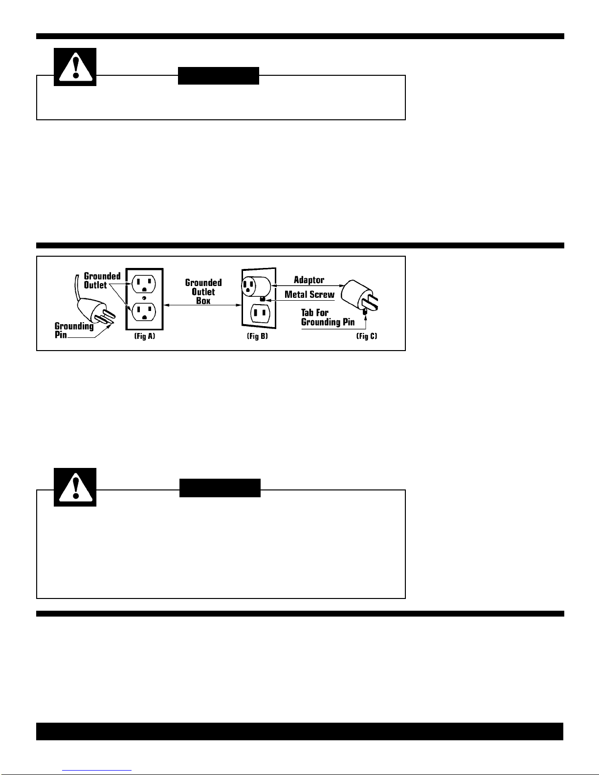
This vacuum must be connected to a
properly grounded outlet only. See
grounding instructions (Page 3)
SAVE THESE INSTRUCTIONS
To reduce the risk of fire, Electric Shock or Injury:
DO NOT expose to rain - Store Indoors
When using this electric vacuum, basic precautions should
always be followed,including the following:
WARNING:
PAGE 2
IMPORTANT
SAFETY
INSTRUCTIONS

Improper use of the grounding plug can result in a
risk of electric shock.
GROUNDING
INSTRUCTIONS
Electrical equipment must be grounded. If
it should mal-function or breakdown,
grounding provides a path of least resist-
ance for electrical current to reduce the
risk of electric shock. This vacuum is
equipped with a cord having an equip-
ment-grounding conductor and grounding
plug. The plug must be inserted into an
appropriate outlet that is properly installed
and grounded in accordance with all local
codes and ordinances.
If repair or replacement of the cord or
plug is necessary, DO NOT connect the
grounded wire to either flat blade termi-
nal. The wire with insulation having an
outer surface that is green with or without
yellow stripes is the grounding wire.
GROUNDING
METHODS
This electric equipment is for use on a
nominal 120 volt circuit, and has a
grounded plug that looks like the plug illus-
trated in (Fig A). A temporary adaptor that
looks like the adaptor illustrated in (Fig B
& C) may be used to connect this plug to
a 2-pole receptacle as shown in (Fig B) if
a properly grounded outlet is not available.
The temporary adaptor should be used
only until a properly grounded outlet (Fig
A) can be installed by a qualified electri-
cian. The green color rigid ear, lug or the
like extending from the adaptor must be
connected to a permanent ground such
as a properly grounded outlet box cover.
Whenever the adaptor is used, it must be
held in place by a metal screw (Fig 3).
Improper connection of the equipment-grounding conductor can result in a risk
of electric shock. Check with a qualified electrician or service person if you are
in doubt as to whether the outlet is properly grounded.
DO NOT modify the plug provided with the equipment. If it will not fit the outlet,
have a proper outlet installed by a qualified electrician.
Note: In Canada, the use of a temporary adaptor is not permitted by the
Canadian Electrical Code.
Treat this vacuum as you would any other
high grade precision made product.
Dropping, unreasonable bumping across
thresholds and other misuses may result
in a damaged to the unit which will not be
covered by warranty.
Read this manual completely before oper-
ating the vacuum. It is important to follow
instructions in this manual to prevent the
possibility of injury or damage to the user
and/or vacuum.
CARE OFTHIS
VACUUM
WARNING:
DANGER:
PAGE 3

DRY & WET
OPERATION
The IT-Vacs are equipped with by-pass
motors, designed for dry or wet pickup.
They are shipped assembled with the
hose, wand and tools packed in the ship-
ping carton.
Dry Operation
This vacuum is shipped with the dry filter
in place and is set up for dry pickup.
Dry Setup
After Wet
Pickup
1. Remove the motor head and set
aside.
2. Lift up on the front handle and tilt
tank back and empty contents into a
suitable drain.
3. Set dry filter assembly on tank,
replace motor head and snap down
clamps.
Setup
for Wet Operation
When using this vacuum for wet pickup
the dry filter must be removed. The float
cage is attached to the bottom of motor
head and remains in place for dry and
wet operation.
1. Disengage holdown clamps remove
motor head and set aside.
2. Remove dry filter, set aside.
3. Replace the motor head, and snap
down clamps.
Always exercise CAUTION when handling the motor head.
Dropping the motor head may cause damage to the internal components.
CAUTION:
PAGE 4
1. Hose to Inlet:
Push the red button on the inlet to the
left and insert hose. Release button and
the hose is connected.
2. Wand Assembly
Push straight ends of wands together.
3. Hose to Wand:
Slide the free end of hose onto one end
of the wand.
4. Wand to Tool:
Select the required tool for vacuuming
and attach it to the free end of wand.
VACUUM MAINTENANCE
Dry Filter
In order to maintain maximum efficiency
of this vacuum cleaner it is important to
clean the cloth filter each time the tank is
emptied.
To clean the cloth filter, shake off loose
particles and brush exposed surface
with a soft bristle brush.
Wet Pickup
DO NOT store this vacuum with any liq-
uids inside the vacuum. Before storing
or converting over for dry pickup run
emptied vacuum for approximately five
minutes to eliminate moisture in the
tank, hose and attachments
Empty liquids from Tank
1. Remove the motor head and dry filter
.Set aside.
2. Lift up on the front handle and tilt the
tank back to empty the contents.
Note: The tank can also be removed
from the dolly by rotating the quick
release system.
HOSE, WAND & TOOLS INSTALLATION

_________________________________
Ref Part Description Qty Part
No No
_________________________________
1 Dolly Handle 1 417270
2 Spacer 2 417084
3 Spiral Spring 2 416983
4 Pivot Hinge 2 417009
5 Support Rod 1 417300
6 Clamp 2 417297
7 5 X 25 Phillips Hd Screw 4 416975
8 Axle Shaft 1 417262
9 Axle Retainer 2 417114
10 5 X 30 Phillips Hd Screw 8 416746
11 Plastic Washer 6 417203
12 5 X 35 Phillips Hd Screw 2 416762
13 M5 X 40 Screw 12 416754
14 Front Caster 2 417025
15 5 X 20 Phillips Hd Screw 8 416703
16 Bushing 2 417211
17 Wheel Spacer 2 417084
18 Rear Wheel 2 416673
19 Washer 2 417017
20 Cap Nut 2 417343
21 Dolly Base 1 417335
_________________________________
TANK TROLLEY
________________________________
Ref Part Description Qty Part
No No
________________________________
1 5 X 30 Phillips Hd Screw 4 416746
2 Poly Tank 1 417327
3 Inlet Gasket 1 417041
4 Inlet Gasket 1 417165
5 Hose Release Button 1 417076
6 Spring 1 417092
7 Tank Inlet 1 417033
8 Inlet Deflector 1 417068
9 Front Handle 1 417238
10 Plastic Washer 2 417203
11 5 X 25 Phillips Hd Screw 2 416975
12 Tank Trim 1 417319
13 Holdown Clamps 2 416967
14 Tank Hinge 1 416991
NS Disposable Filter Bags (5/Pk) 1 432423
________________________________
TANK & TROLLEY
REPLACEMENT
PARTS LIST
15 GALLON POLY TANK
PAGE 5

________________________________
Ref Part Description Qty Part
No No
________________________________
1 Motor Head Handle 1 417246
2 Dome Cover 1 416053
3 5 X 20 Phillips Hd Screw 11 416703
4 5 X 30 Phillips Hd Screw 2 416746
5 Terminal Block 1 416665
6 Vacuum Cap 2 438723
7 Dome 1 416843
8 Anti-Splash Switch 1 416584
9 Motor Holdown 1 416851
10 Silencing Foam 3 416894
11 Plastic Ring 1 416568
12 Gasket 6 416525
13 11/2 HP,120 Volt Motor 1 416797
14 Washer 2 416711
15 M4 X 8 Screw 2 416770
16 Automatic Valve 2 416606
17 Motor Base Assembly 1 416657
18 5 X 14 Phillips Hd Screw 12 416681
19 Plastic Motor Spacer 2 438758
20 Deadening Triangle (Base) 3 416940
21 Gasket 1 416576
22 Foam Filter 3 438731
23 27 Ft, 3/16 Power Cord 1 416827
24 5 X 35 Phillips Hd Screw 8 416762
25 Locknut 1 416541
27 Strain Relief 1 416533
28 Motor Cap 2 438766
________________________________
SINGLE MOTOR HEAD
REPLACEMENT
PARTS LIST
TOOL, HOSE AND WAND
PAGE 6
1
2
3
6
4
5

PAGE 7
___________________________________
Ref Part Description Qty Part
No No
___________________________________
1 Motor Head Handle 1 417246
2 Dome Cover 1 416053
3 5 X 20 Phillips Hd Screw 11 416703
4 5 X 30 Phillips Hd Screw 2 416746
5 Terminal Block 1 416665
6 Dome 1 416843
7 Anti-splash Switch 2 416649
8 Gasket 1 416576
9 Motor Holdown 1 416851
10 Silencing Foam 3 416894
11 Plastic Ring 2 416568
12 Motor Gasket 4 416525
13 2 - 1 HP, 120 Volt Motor 2 416789
14 Washer 2 416711
15 M4 X 8 Screw 2 416770
16 Automatic Valve 2 416606
17 Motor Base Assembly 1 416657
18 Motor Cap 1 438766
19 Motor Spacer 1 438758
20 Deadening Triangle 3 416940
21 Vacuum Cap 1 438723
22 Foam Filter 3 438731
23 5 X 35 Phillips Hd Screw 8 416762
24 Cord Clamp 1 416541
25 4.3 X 22 Screw 2 416738
26 Strain Relief 1 416533
27 27 Ft, 3/16 Power Cord 1 416827
28 5 X 14 Ph Hd Screw 12 416681
___________________________________
TOOL, HOSE AND
WAND PARTS LIST
DUAL MOTOR HEAD
REPLACEMENT
PARTS LIST
_____________________________
Ref Part Description Qty Part
No No
_____________________________
1 3 Piece Plastic Wand 1 456020
2 10 Ft Vinyl Hose 1 422576
3 Dusting Brush 1 432830
4 16" Squeegee Tool 1 435503
5 Crevice Tool 1 422533
6 16" Floor Tool 1 433187
N/S Reducer 1 433268
_____________________________

IT-Vac Manual - PN 412600 Rev A - Printed in USA 03/22/05
TROUBLE
SHOOTING
GUIDE
PROBLEM: Lose of vacuum.
POSSIBLE CAUSE: POSSIBLE SOLUTION:
1. Cloth filter clogged. 1. Clean cloth filter.
2. Clogged hose or wand. 2. Remove obstruction.
3. Tank rim damaged 3. Replace tank.
4. Loose or broken fan. 4. Contact manufacturer or service center.
5. Motor not working. 5. Contact manufacturer or service center.
6. Float not functioning. 6. Check to see if float moves freely.
7. Tank full. 7. Drain dirty water from tank.
PROBLEM: Motor or pump is not running.
POSSIBLE CAUSE: POSSIBLE SOLUTION:
1. Broken switch. 1. Contact manufacturer or service center.
2. Power cord defective. 2. Contact manufacturer or service center.
3. Motor or pump defective. 3. Contact manufacturer or service center.
4. Blown fuse or tripped circuit 4. Replace fuse or reset circuit breaker.
breaker.
PROBLEM: Dust blowing from vacuum when running.
POSSIBLE CAUSE: POSSIBLE SOLUTION:
1. Cloth filter bag dirty. 1. Clean cloth filter bag.
2. Cloth filter bag is torn or missing. 2. Replace.
PROBLEM: Water blowing from vacuum when running.
POSSIBLE CAUSE: POSSIBLE SOLUTION:
1. Tank is full of liquid. 1. Empty tank.
2. Sudsy or foamy liquid is being 2. Add defoamer to tank.
picked up.
PAGE 8
______________________________
Ref Part Description Qty Part
No No
______________________________
1 Wire Mesh Filter 1 417254
2 Float 1 417106
3 Spacer 1 417351
4 5 X 25 Screw 4 417289
5 Float Cage 1 417122
6 Plastic Frame 1 417130
7 Filter Ring 1 416630
8 Cloth Filter Bag 1 417157
Optional Filter
9 Cartridge Filter 1 417173
10 Cartridge Filter Ring 1 417181
______________________________
DRY FILTER AND
FLOAT CAGE
REPLACEMENT
PARTS LIST
Address:
777 South Street
P.O. Box 2310
Newburgh, NY 12550-0606
TEL:
(800) 835-7812
(845) 565-8850
FAX:
(800) 752-6883
(845) 565-9392
URL:
www.mastercraftusa.com
E-mail:
This manual suits for next models
1
Table of contents
Other MasterCraft Vacuum Cleaner manuals

MasterCraft
MasterCraft ENVIROMASTER 9 Installation manual

MasterCraft
MasterCraft 54-3672-4 User manual

MasterCraft
MasterCraft P42010SMP Guide

MasterCraft
MasterCraft QuietMaster Guide

MasterCraft
MasterCraft Wide Area Vacuum Guide

MasterCraft
MasterCraft AquaRinse User manual

MasterCraft
MasterCraft 14" Installation manual