Masterpiece FreeMo Module Kit User manual

Masterpiece Module Kits
FreeMo Module Kit Assembly Instructions
For tips, watch Instructional Video at http://www.youtube.com/watch?v=fKleBFFclaU
Tools Required –flat, sturdy work surface
Quality grade wood glue such as Tite Bond III
Hammer or mallet and wood block, Philips Screwdriver
DO NOT press pieces together before gluing. All pieces are cut on a CNC router and are a precision
press fit. Assembling them without glue to check the fit may seem like a good idea, but when you
try to disassemble to add glue, you risk delaminating parts of the plywood.
When using a hammer, place a block of wood on the module components as a buffer, tapping on
the block of wood rather than the module components. This will prevent the hammer from marring
the module component surface. Also, make sure the module is supported by a sturdy work surface
that will withstand the action of the mallet or hammer. (the floor works fine for this)
1. Using the sandpaper pieces included in this kit, remove all the fuzz and splinters on the
perimeter of all the parts.
2. Lay out all the parts and get familiar with how they interlock and fit together. Refer to PARTS
LIST on Page 4.
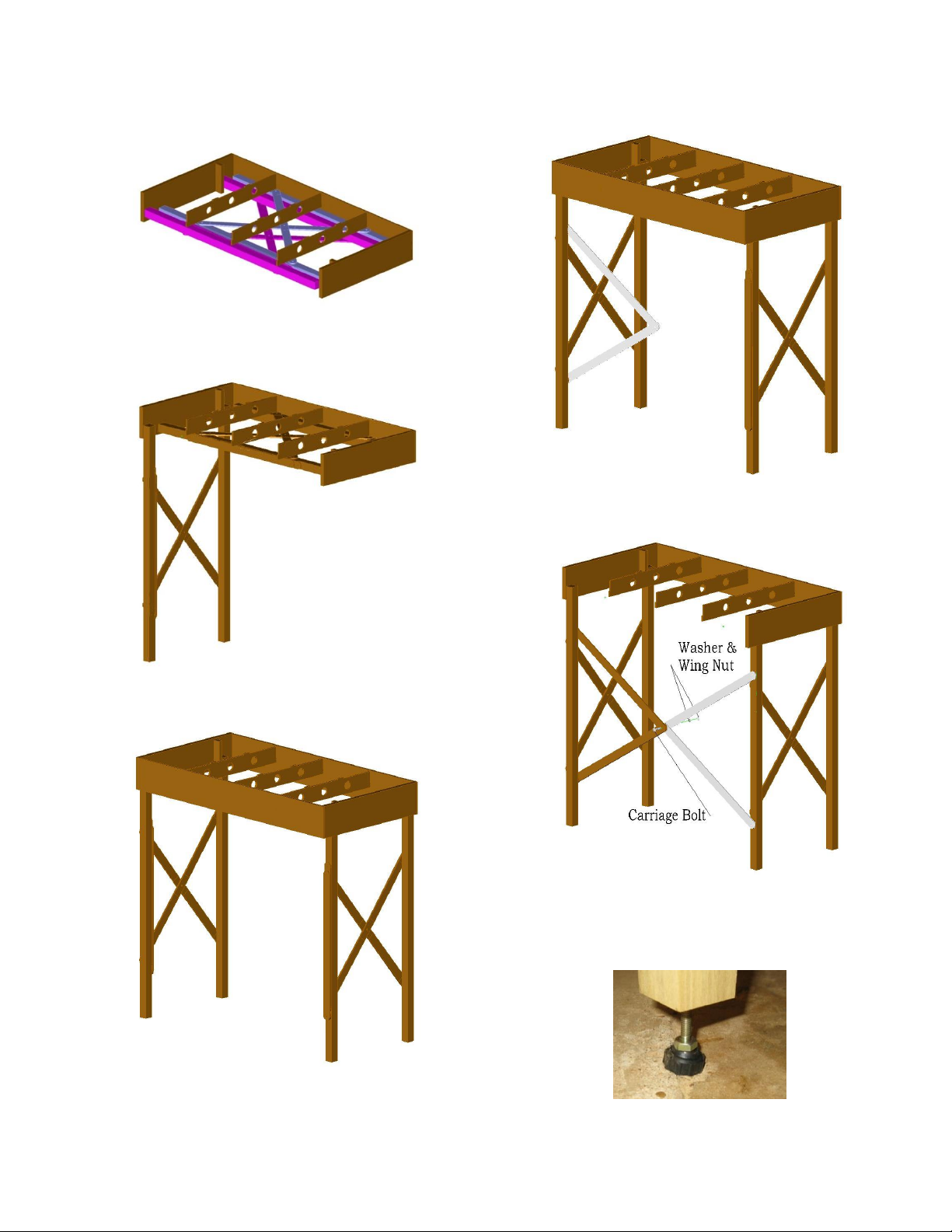
3. We will begin assembling this module right side up on a sturdy work surface. This could be a
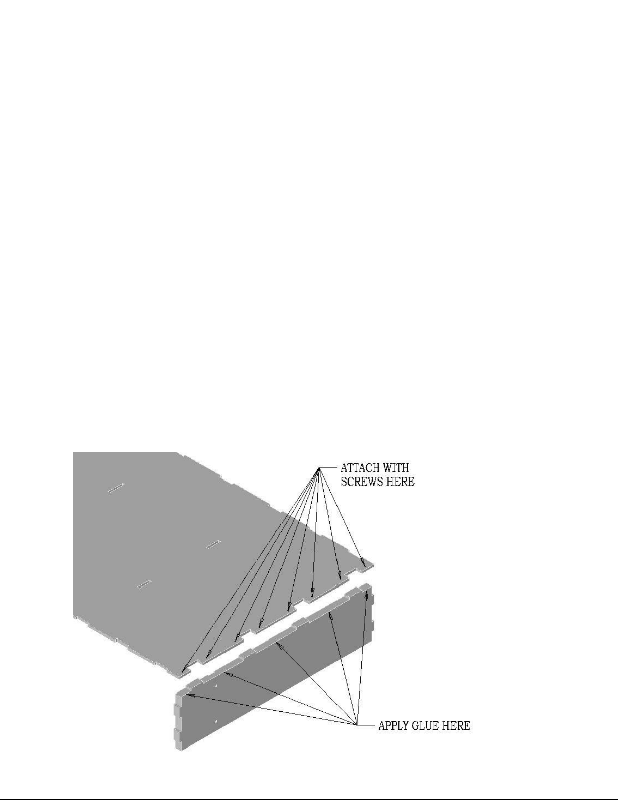
table, workbench or the floor if it is flat. Select one of the Deck End Plates and make sure the finger
sizes match the slot sizes in the deck and the alignment pin in the end plate is on the outside of the
module. Spread glue on the top edge of the Deck End Plate between the fingers. Fit the Deck in
place as shown, using the other end plate to raise the other end to keep the Deck parallel with the
work surface. Make sure Deck is tight against the End Plate fingers and install #6 –5/8 FH Wood
Screws as shown. Repeat with other end.

Page 2
4. Turn Deck and Ends over on bench and install Deck Braces as shown. Use a mallet and block of
wood to force the tabs into their holes in the deck.

Page 3
5. Turn the module assembly up on one side as shown below. Locate and check fit of Module Side
to Deck, Deck Braces and Module Ends. Spread glue on surface of Module Ends, Module Side and
Deck Braces as shown. Start fitting side with end and work your way toward the other end of the
module as you tap the Module Side fingers into their notches in the Deck. The fit of fingers of the
side plate to the End Plate are a size on size fit which should require no pressure to match-up. The
fit of the fingers to the Deck are an interference press fit that will require a mallet and a block of
wood or clamps to pull the two piece together. Once the fingers are properly seated, install #6 x
5/8” FH Philips self-tapping SS screws to secure the sides to the end plates. Tip the assembly Deck
side up and using a block of wood and a mallet, make sure the Deck is firmly seated on the side
fingers.
6. Turn the module assembly over and attach the other Module Side using the same technique.

Page 4

Page 5
7. Turn module assembly back on its deck. Locate and check the fit of the Leg Pivot Blocks. Apply
glue as shown and attach pivot blocks at each end with two #10 x 1-1/4” wood screws.
8. Attach Legs #1 & #2 - Locate Legs labeled 1 & 2 and the hardware shown. Install leg#1 in corner
marked 1. Install leg #2 in corner marked 2. Make sure the rounded corner on the end of the leg is
oriented toward the outside of the module as shown. Tighten the hex nut snug but not so tight to
keep the leg from pivoting.

Page 6
9. Attach bracing to Legs 1 & 2 - Locate two of the long leg braces and four #10 x 1” wood screws.
Attach first brace as shown, using pre-drilled holes in legs. Attach second brace with screws.
10. Attach Legs #3 & #4 - Locate Legs labeled 3 & 4 and the hardware shown. Install leg#3 in
corner marked 3. Install leg #4 in corner marked 4. Make sure the rounded corner on the end of the
leg is oriented toward the outside of the module as shown. Tighten the hex nut snug but not so
tight to keep the leg from pivoting.

Page 7
11. Attach braces to Legs 3 & 4 - Locate two of the long leg braces and four #10 x 1” FH Wood
Screws. Attach first brace as shown, using pre-drilled holes in legs. Attach second brace with
screws.
Fold legs into module and check for fit. Adjust as needed and then
Apply glue to the center portion of the end leg braces where they cross. Apply a clamp to glue joint
until glue has set.

Page 8
11. Attach Front Braces to Leg #2 - Locate two of the short leg braces, one leg brace spacer and two
#10 x 1-1/2” wood screws. Attach braces as shown, using pre-drilled holes in legs.
12. Attach Front Braces to Leg #3 - Locate two of the short leg braces, one leg brace spacer and two
#10 x 1-1/2” wood screws. Attach braces as shown, using pre-drilled holes in legs. Insert ½-20 x 1-
1/4 carriage bolt into all four front leg braces and install ¼” washer and ¼-20 wing nut.

Page 9
13. Install Leg Retainers as shown to Legs 1 and 2 using #10 x 1” FH Wood Screws. Tighten the
screw snug so it will stay in place, but loose enough that it can be rotated to hold the legs in their
folded position. This keep the legs folded when transporting and handling the module. Simply turn
them to align with the leg and the legs can easily be unfolded and the module set up.
14. Insert Leg Leveler Screws into threaded inserts in ends of all four legs.
15. Turn module over and start laying track!

Page 10
Setting up your Module –top deck is not shown for illustrative purposes
To begin, you should have two people, one on each
end of the module. Reaching under the module, pull
down both leg sets as shown below.
One Leg set down
Two leg sets down.
Swing out the braces attached to the left leg
as shown.
Swing out the braces attached to the right
leg, insert carriage bolt through all 4 braces
and install wing nut as shown.
Adjust feet as needed.

Page 11
Parts List
24" x 48" FreeMo Module Kit
Qty
description
1
Deck
2
End Plates w/ steel pin, bushing a & threaded inserts
2
Leg Pivot Blocks
2
Side Plates
1
Deck Brace - center
2
Deck Braces
1
Leg - #1
1
Leg - #2
1
Leg - #3
1
Leg - #4
4
End Leg Braces - Long
4
Front Leg Braces - Short
1
Hardware Pack (contains the following)
4
1/4-20 x 3" Carriage Bolt (adjustable foot)
2
1/4-20 x 2-3/4" Carriage Bolt (leg pivot)
2
1/4-20 x 2-1/4" Carriage Bolt (leg Pivot)
1
1/4-20 x 1-1/4" Carriage Bolt (leg bracing)
4
1/4" Flat Washer
4
1/4-20 ESNA Hex Lock Nut
1
1/4-20 Wing Nut
18
#10 x 1 FH Philips Wood Screw
30
#6-5/8 Flat Head Philips Wood Screw
2
Front Leg Brace Spacer (round wooden disk)
2
Leg Retainers
Tips for finishing your modules.
1. Before painting, seal wood with a sanding sealer. We recommend using Zinzer Shellac thinned
with denatured alcohol –one part shellac to one part alcohol. This can be easily and quickly
brushed on in a well ventilated area. It should be dry for sanding within 15 minutes. We do not
recommend sealing and painting the top surface of the module until after you have glued your
roadbed and any other object that you plan to glue to the deck.
2. Be careful to not get paint on the locating pins and bushings on the module end plates.
Popular Indoor Furnishing manuals by other brands

Extreme marquees
Extreme marquees 19m x 12m DOUBLE POLE STAR SHADE installation instructions

mothercare
mothercare padstow changer User's guide & installation instructions

StyleWell
StyleWell DP18009-TABLE Use and care guide

Via Seating
Via Seating 4U Adjustment guide

Ameriwood
Ameriwood 5518012PCOM manual

Rauch
Rauch M2609 Assembly instructions

OSP Designs
OSP Designs HELENA HLN25 Assembly instructions

VISIONARY DESIGNS
VISIONARY DESIGNS MOD-1543 Setup instructions

Muckle Mannequins
Muckle Mannequins Iron man 3 manual

ofichairs
ofichairs Wind manual

Vivo
Vivo MOUNT-KB05F instruction manual

Furniture of America
Furniture of America CM3738T Assembly instructions