8
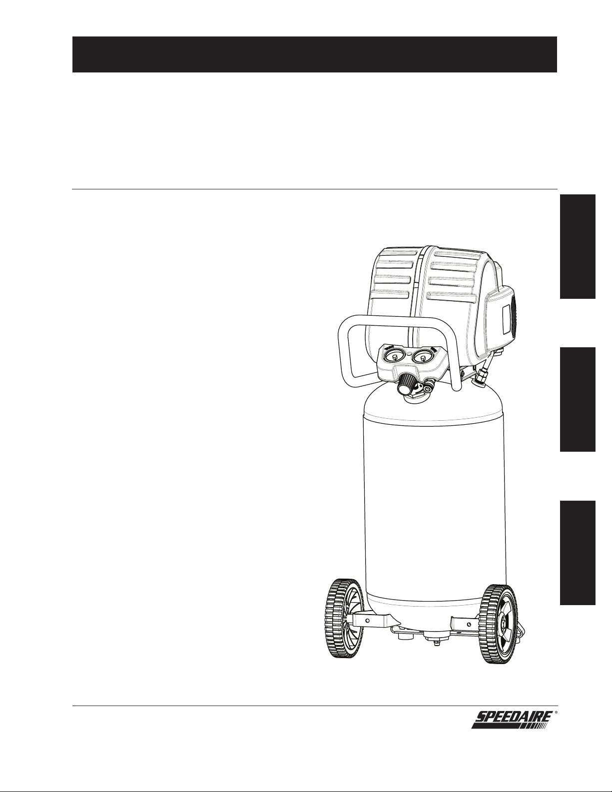
Speedaire Operating Instructions
E
N
G
L
I
S
H
Assembly / Installation
Assembling the Compressor Installation
The air compressor
should be turned
off, unplugged from the power source,
the air bled from the tank and the
unit allowed time to cool before any
maintenance is performed. Personal
injuries could occur from moving parts,
electrical sources, compressed air or hot
surfaces. The quick connect assembly
must be attached before use. Failure to
assemble correctly could result in leaks
and possible injury.
If unsure of assembly instructions or
you experience difficulty in the assembly
please call your local service department
for further information.
1. Unpack the air compressor. Inspect
the unit for damage. If the unit has
been damaged in transit, contact
the carrier and complete a damage
claim. Do this immediately because
there are time limitations to damage
claims.
2. Check the compressor’s serial label
to ensure that you have received the
model ordered, and that it has the
required pressure rating for its
intended use.
3. Locate the compressor according to
the following guidelines:
a. Position the compressor near
a grounded electrical outlet.
b. The compressor must be at
least 12 inches (31 cm) from
any wall or obstruction, in a
clean, well-ventilated area, to
ensure sufficient air flow and
cooling.
c. In cold climates, store portable
compressors in a heated
building when not in use. This
will reduce problems with
motor starting and freezing of
water condensation.
d. Remove the compressor from
the carton and place it on the
floor or a hard, level surface.
The compressor must be level
to ensure proper drainage of
the moisture in the tank.
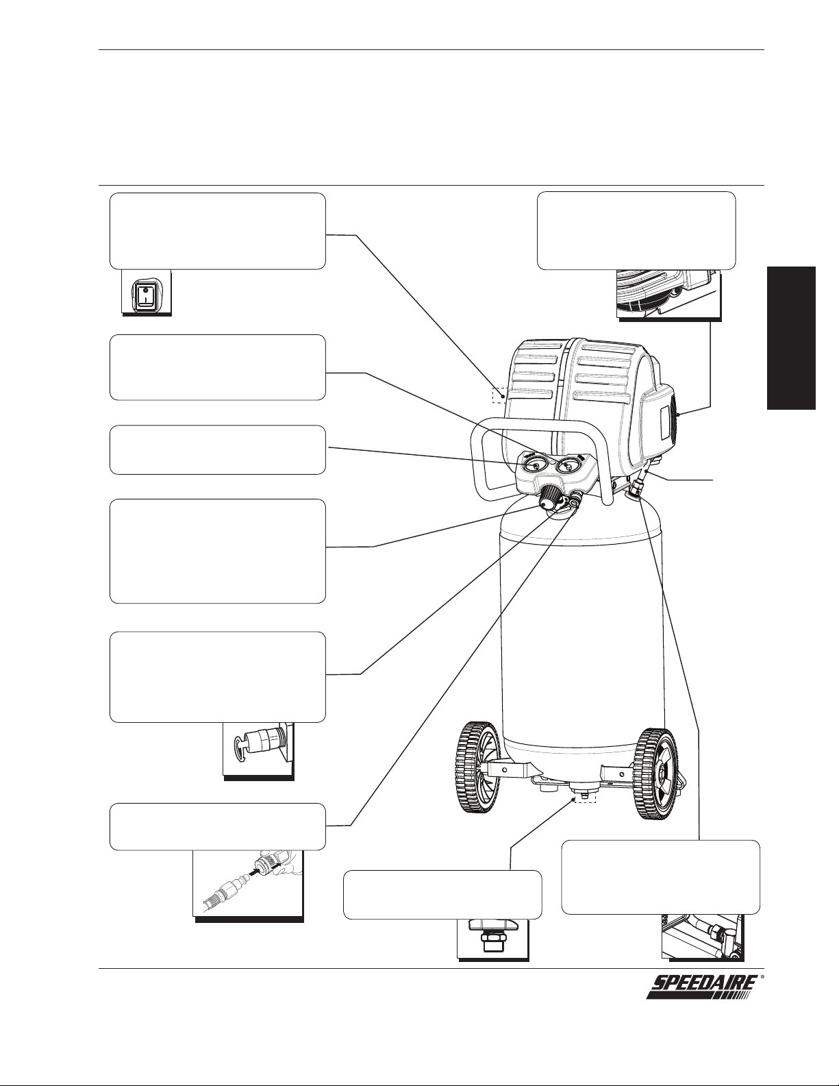
Location of the Air Compressor
The air compressor should always be
located in a clean, dry and well ventilated
environment. The unit should have at
minimum, 12 inches of space on each
side. The air filter intake should be free
of any debris or obstructions. Check the
air filter on a daily basis to make sure it is
clean and in working order.
Risk Of Fire Or Explosion
This product incorporates snap action
switch contacts and a universal electric
motor which tends to produce arcs
and sparking and therefore should not
be exposed to flammable liquids or
vapors. This product is not intended
for installation or use in a commercial
garage or shop environment.
Grounding Instructions
This product must be grounded. In
the event of an electrical short circuit,
grounding reduces the risk of electric
shock by providing an escape wire
for the electric current. This product
is equipped with a cord having a
grounding wire with an appropriate
grounding plug. (See Figure 3.) The
plug must be plugged into an outlet
that is properly installed and grounded
in accordance with all local codes and
ordinances. Check with a qualified
electrician or service personnel if
these instructions are not completely
understood or if in doubt as to whether
the tool is properly grounded.
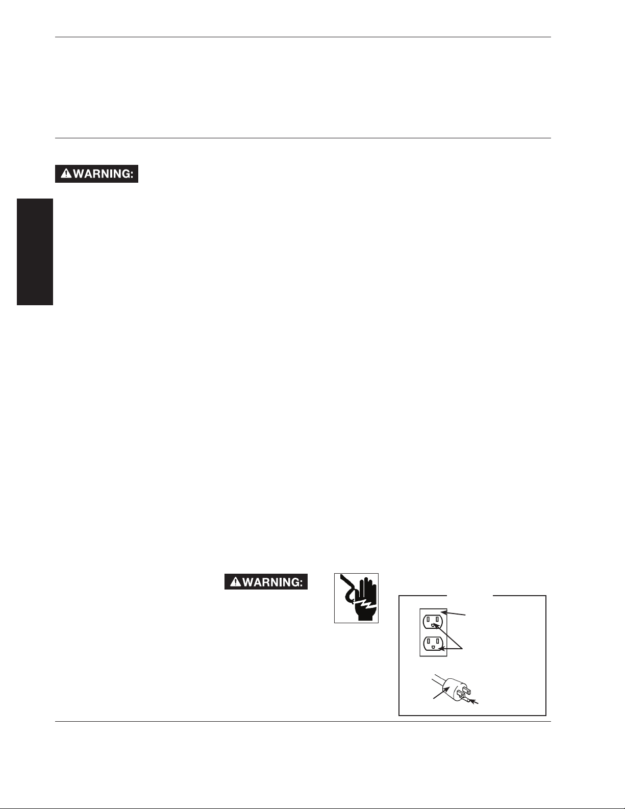
Improper installation of the
grounding plug will result
in a risk of electric shock.
If repair or replacement
of the cord or plug is necessary, do
not connect the grounding wire to
either flat blade terminal. The wire with
insulation having an outer surface that
is green with or without yellow stripes
is the grounding wire. Substitution
of the signal word “DANGER” for
“WARNING” is not prohibited when
the risk associated with the product is
such that a situation exists which if not
avoided will result in death or serious
injury. Check with a qualified electrician
or serviceman if the grounding
instructions are not completely
understood, or if in doubt as to whether
the product is properly grounded. Do
not modify the plug provided; if it will
not fit the outlet, have the proper outlet
installed by a qualified electrician.
This product is for use on a nominal
120-V circuit and has a grounding plug
similar to the plug illustrated in (Figure
3). Only connect the product to an outlet
having the same configuration as the
plug. Do not use an adapter with this
product.
Extension Cords
Use only a 3-wire extension cord that
has a 3-blade grounding plug, and a
3-slot receptacle that will accept the
plug on the product. Make sure your
extension cord is in good condition.
When using an extension cord, be
sure to use one heavy enough to carry
the current your product will draw.
Cords must not exceed 50 feet and
No. 12 AWG size must be used. An
undersized cord will cause a drop in line
voltage resulting in loss of power and
overheating.
Break In Procedures
No break in procedure is required
by the user. This product is factory
tested to ensure proper operation and
performance.
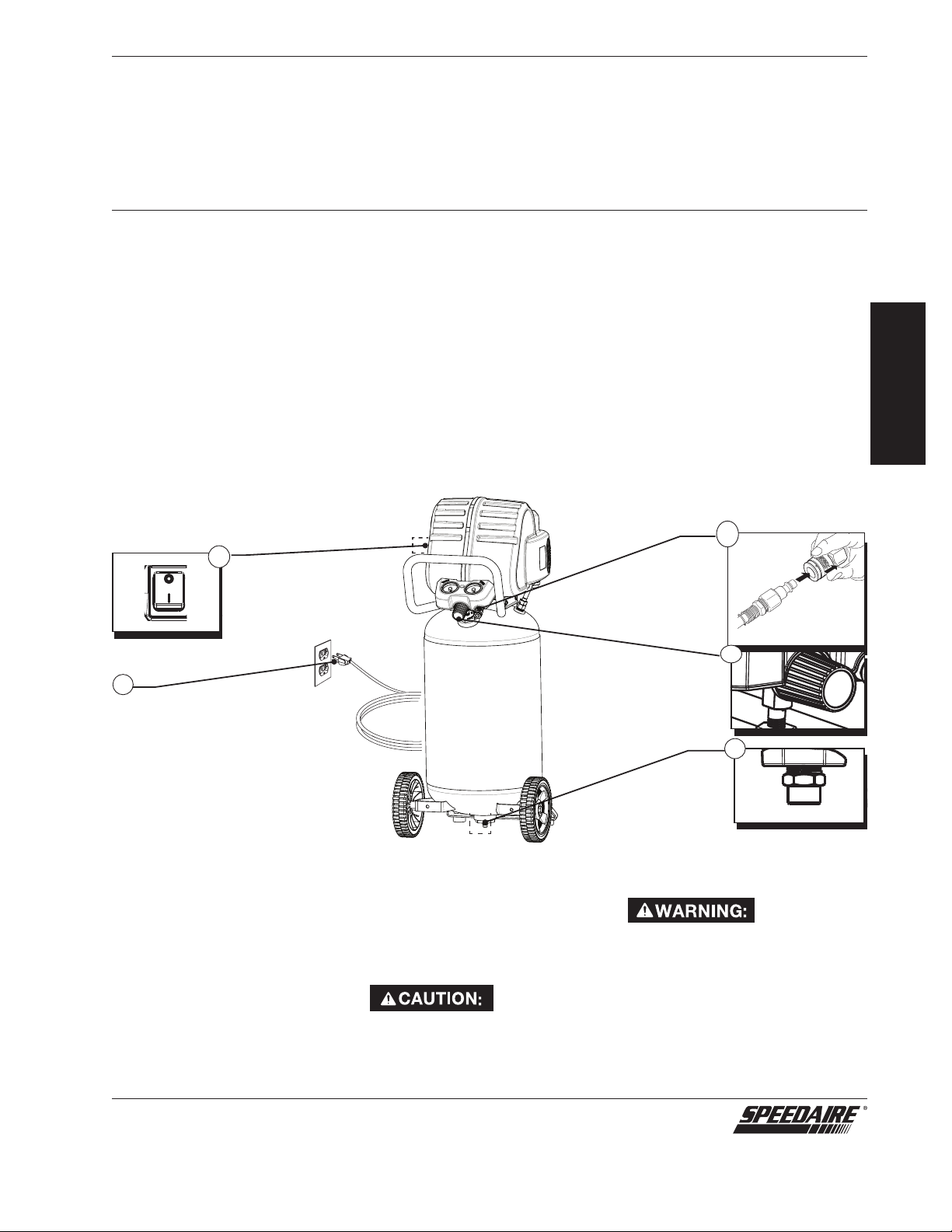
Figure 3
Grounded Outlet
Box
Grounded Outlet
Plug Grounding Pin
120 VOLTS