AU SUPPORT 1800 237 425 WWW.MATCHMASTER.COM.AU | NZ SUPPORT 0800 237 425 WWW.MATCHMASTER.CO.NZ PAGE | 1 OF 3
34MM-2K50-3
INSTRUCTION MANUAL
AFTER-SALES SERVICE
INTRODUCTION
FEATURE
PACKAGE LIST
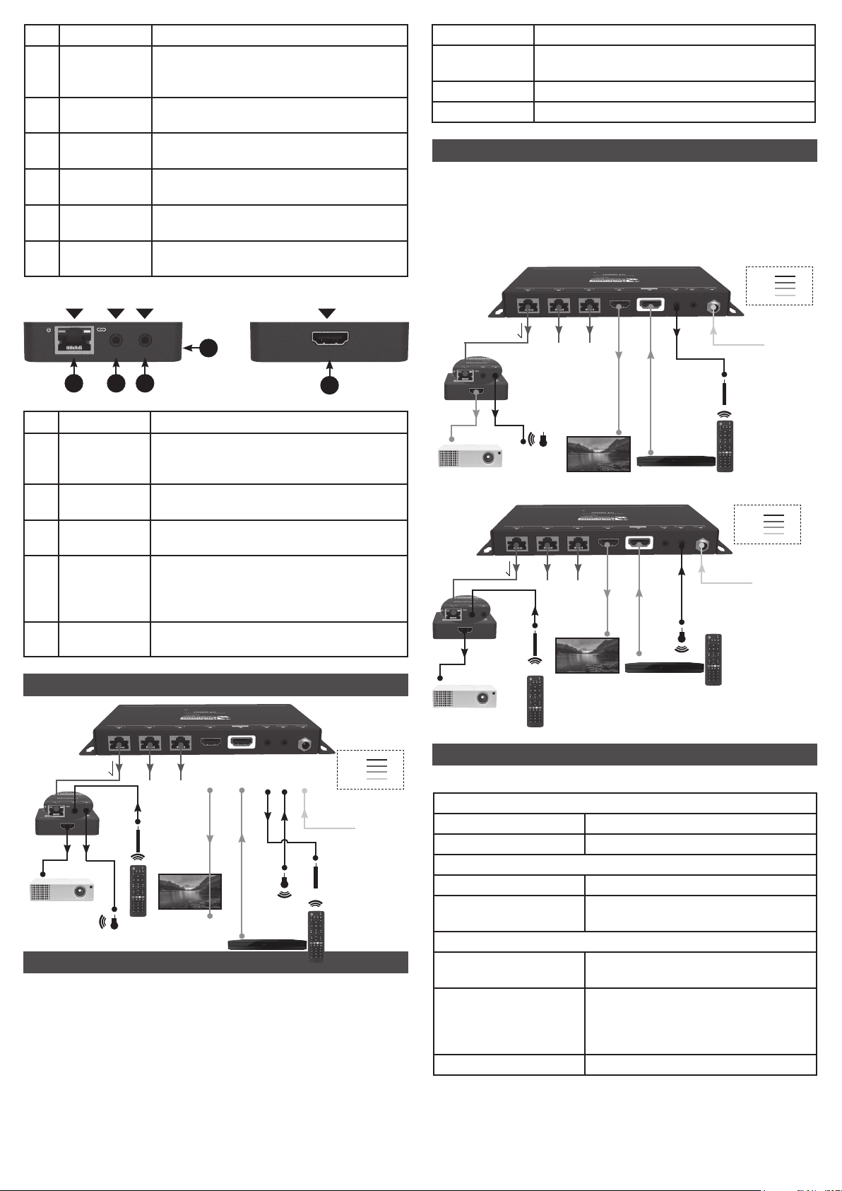
PANEL DESCRIPTION
STATEMENT
SAFETY WARNING
Read this user manual carefully before using the product.
Pictures shown in this manual is for reference only, different
model and specications are subject to real product.
This manual is for operation instruction only, not for any
maintenance usage. The functions described in this version
are updated till March 30, 2020. In the constant effort to
improve our product, we reserve the right to make functions
or parameters changes without notice or obligation. Please
refer to the dealers for the latest details.
Splitter Front Panel
We provide limited warranty for the product
within three years.
Thanks very much for purchasing this HDMI 1x4 Splitter KIT!
This device accepts a single HDMI input and splits it into
three RJ45 outputs and one HDMI output. It supports video
resolutions up to 1080p@60Hz and all HDMI audio formats.
It can extend 1080p signals on each output to up to 164 feet
(50 meters) over a single CAT6a Ethernet cable. It supports
the Power over Cable (PoC) feature, which allows the
included receivers to be powered from the splitter over the
Ethernet cables. It also supports bidirectional IR.
Please read this entire manual before using this device,
paying extra attention to these safety warnings and
guidelines. Please keep this manual in a safe place for
future reference.
• Do not expose this device to water or moisture of
any kind. Do not place drinks or other containers with
moisture on or near the device. If moisture does get in
or on the device, immediately unplug it from the power
outlet and allow it to fully dry before reapplying power.
• Do not touch the device, the power cord, or any other
connected cables with wet hands.
• Do not expose this device to excessively high
temperatures. Do not place it in, on, or near heat
sources, such as a replace, stove, radiator, etc. Do not
leave it in direct sunlight.
• Prior to operation, check the unit and power cord for
physical damage. Do not use if physical damage
has occurred.
• Unplug this device from the power source when
not in use.
• Take care to prevent damage to the power cord. Do
not allow it to become crimped, pinched, walked on, or
become tangled with other cords. Ensure that the power
cord does not present a tripping hazard.
• Never unplug the unit by pulling on the power cord.
Always grasp the connector head or adapter body.
• Ensure that power is turned off and disconnected before
making any electrical connections.
• Clean using a soft, dry cloth only. Do not use chemical
cleaners, solvents, or detergents. For stubborn deposits,
moisten the cloth with warm water.
• This device has no user serviceable parts. Do not
attempt to open, service, or modify this device.
• Splits a single HDMI input to three RJ45 outputs.
• Supports video resolutions up to 1080p@60Hz.
• Extends 1080p signals on each output to distances up to
164 feet (50 meters) over a single CAT6 cable.
• Supports the Power over Cable (PoC) feature, allowing
the receivers to be powered by the splitter over the
Ethernet cables.
• 1 by 3 IR matrix with receivers, bidirectional IR control
for exible control.
• Smart EDID management. Features DIP switch to select
the output resolution 720p or 1080p to match the
connected displays.
• Fully compliant with the HDMI 1.4 and HDCP
1.4 specication.
Please make sure all the items listed below are in the
package. If anything is missing or damaged, please contact
your distributor for a replacement.
• 1x splitter
• 3x receiver
• 1x IR transmitter
• 3x IR receiver
• 1x power supply
1 2 3 4
No. Name Description
1 Power LED The LED illuminates red when power
is applied.
2 Input LED The LED illuminates blue when there is
an input source present.
3 Output LED The LED Illuminates blue when there is
HDMI output
4 EDID DIP switch for setting the Extended
Display Identication Data
(EDID) value.
OUT 1 OUT 2 OUT 3 OUT 4 SOURCE IR IN IR OUT DC 12V
1 2 3 4 5 6
Splitter Rear Panel