PAGE 2 OF 4 | FOR TECHNICAL SUPPORT CALL 1800 237 425 OR VISIT WWW.MATCHMASTER.COM.AU
2.3 Top Panel Introduction
1. F connector male for LNB IN
2. F connector male for ANT IN
3. USB connector
4. HD TV connector
5. AV OUT connector (3.5 PHONE JACK)
6. AV IN connector (3.5 PHONE JACK)
7. Reset key
8. DC jack (for charger)
2.4 Rear Panel Introduction
1. LED oodlight
2. Stand
3. Loudspeaker
4. Battery
5. Protective rubber edge
3 DETAILED OPERATION GUIDE
When you turn on the device, you will
see the main menu which consists of
Satellite, Terrestrial, System Setting,
Program, Multimedia and Upgrade.
3.1 Satellite
3.1.1 Spectrum Analyzer
Move cursor to“Spectrum Analyzer’’
and press“ OK’’, then you can enter
the“Parameter Setting’’ interface.
1. Press [F1] to switch SPAN of
spectrum frequency, FULL as
default. The smaller span will show
clearer signal status of frequencies.
2. Press [F4] to pause current status.
3. Press [ / ] to move vertical
coordinate’s position.
4. Press[ / ] to move cursor
to select frequency, the signal
strength of the selected frequency
will be displayed on the left-top
corner.
3.1.2 Constellation Analyzer
Move cursor to “Constellation
Analyzer’’ and press “OK’’, then you
can enter the “Constellation Analyzer’’
interface.
1. Press [ / ] to move cursor to
choose“Analyze by Frequency’’
and press“OK’’ , then you can see
this interface.
2. Press [ / ] to select satellite
and you can see the Transponder
changes correspondingly.
3. Press [ / ] to select
Transponder and you can see
TP frequency, Symbol Rate and
Polarity change correspondingly.
4. Press“OK ’’, then you can see the
quality bar and the strength bar.
5. Under Constellation Analyzer
interface (by Frequency), press [
/ ] to switch between other
Frequency of selected satellite
6. Press “EXIT’’ and press [ / ] to
move cursor to choose “Analyze by
Program’’ and press “OK’’, then you
can see this interface.
7. Under Constellation Analyzer
interface (by Program), press
[ / ] to switch between all the searched program.
8. When a frequency with signal is detected(not locked yet), the signal
strength bar will be displayed on LCD.
9. When the signal is locked, The signal quality bar will be displayed on the
LCD. Meanwhile, the LOCK LED will light up.
3.1.3 Satellite Setting
Move cursor to “Satellite Setting’’ and
press“OK’’, then you can enter the
“Dish Setup’’ interface.
1. Under the Satellite list page, you
can press [ / ] to select the
satellite.
2. Press [F1] to add a new satellite
through setting Satellite Name,
Longitude Direction, Longitude Angle or Band.
3. Press [F2] to edit existed satellite,
which is including Satellite Name,
Longitude Direction, Longitude
Angle and Band.
5. Press[F4]to Begin Scan, with
Default, Blind Scan, Network these
three scan modes. When the
signal is locked, the buzzer will
sound with the fastest repetition.
The signal quality bar will also be
displayed on the LCD. Meanwhile,
the LOCK LED will light up. (Press
“MUTE’’ to close the buzzer sound
if you don’t want to hear it.)
7. Select one of the satellites and
press [ / ] to get into the LNB
TYPE setting.
8. LNB Type: Press [ / ] to
choose LNB Type between
9750/10600, 9750/10750, 05150,
05750, 09750, 10600, 10700,
10750, 11300 and 11475.
10. 22K: Choose AUTO/ON/OFF.
4. Press [F3] to delete existed
satellite. If you press OK, the
satellite will be deleted or you can
press “EXIT’’ to exit.
6. Press [GOTO] to get into the TP
list, you can also use [F1] [F2] [F3]
[F4] to add, edit, delete or begin
to scan the selected TP, and Press
[GOTO] to return to the satellite
list.
9. LNB Power: Press [ / ]
to choose between Off/13V/
(13V/18V)/18V.
11. Toneburst: Press [ / ] to
choose between None/BurstA/
BurstB.
12. DiSEqC1.0: Press [ / ] to
choose between None/LNB1/
LNB2/ LNB3/LNB4.
13. DiSEqC1.1: Press [ / ]
to choose between None/
LNB1~LNB16.
14. Motor: Press [ / ] to choose
between None/DiSEqC1.2/
DiSEqC1.3.
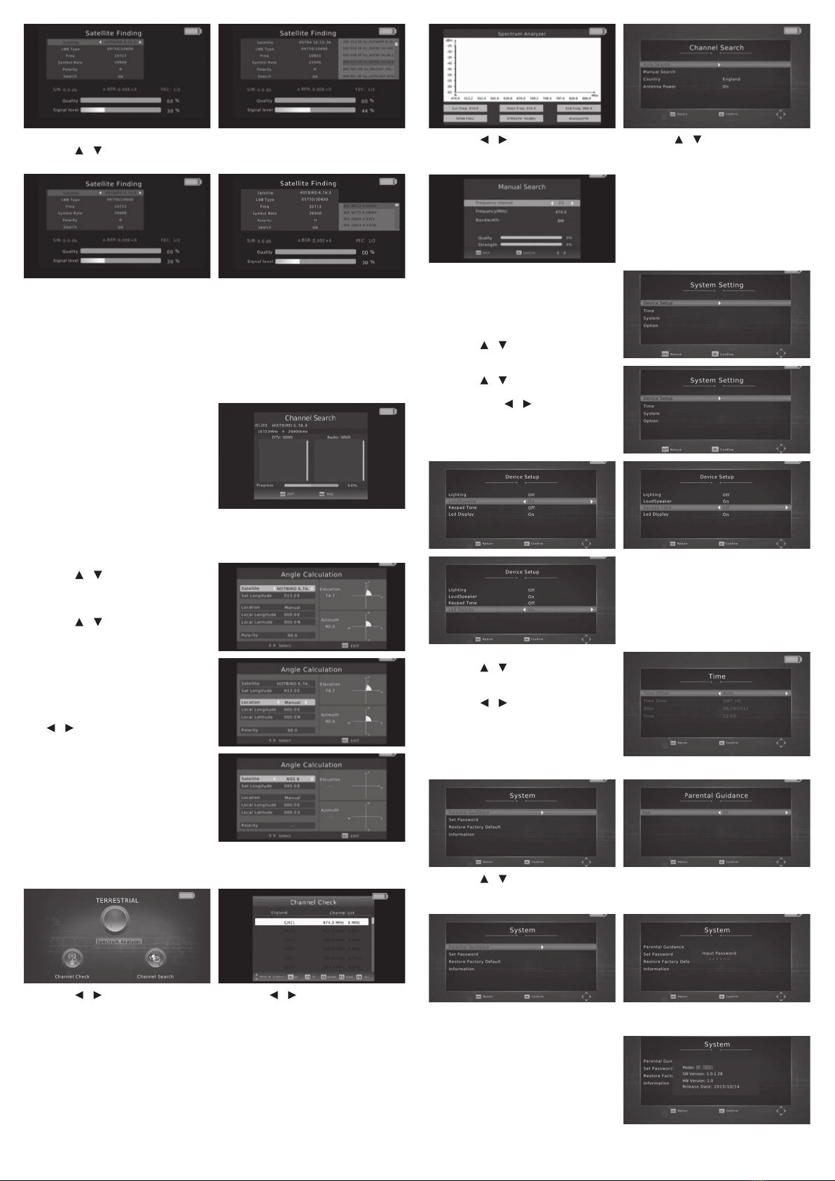
3.1.4 Satellite Finding
Move cursor to “Satellite Finding’’ and press “OK’’, then you can enter the
“Satellite Finding’’ interface.
1 2 3 4 5 6 7 8
1
4
5
2 3