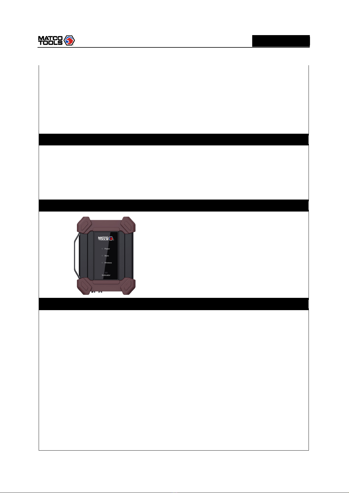
High Level 2-Channel Lab Scope with built in Multimeter
i
WARNING
Study, understand and follow all instructions provided with this product. Read these instructions
carefully before installing, operating, servicing or repairing this tool. Keep these instructions in a safe,
accessible place.
Caution: To help prevent personal injury,
Handle device carefully. Do not drop, bend, puncture, insert foreign objects, or place heavy
objects on the device. The fragile components inside the unit may be damaged.
Connect and Disconnect Properly. Do not connect or disconnect probes or test leads while
they are connected to a voltage source.
Observe All Terminal Ratings. To avoid fire or shock hazard, observe all ratings and markings
on the product. Consult the product manual for further ratings information before making
connections to the product.
Use Proper Probe. To avoid shock hazard, use a properly rated probe for your measurement.
Avoid Circuit or Wire Exposure. Do not touch exposed connections and components when
power is on.
Do Not Operate With Suspected Failures. If suspected damage occurs with the device, have
it inspected by qualified service personnel before further operations.
Do not operate in Wet/Damp Conditions.
Do not operate in an Explosive Atmosphere.
Keep product surfaces Clean and Dry.
Do not disassemble or refit the device. The device is a sealed device and there are no
end-user serviceable parts inside. All internal repairs must be carried out by authorized
maintenance agencies or authorized technicians. Attempts to disassemble or refit the device
will void the warranty.
Do not try to replace the internal battery. The internal rechargeable battery must be replaced
by authorized maintenance agencies or authorized technicians.
AVERTISSEMENT
Étudiez, comprenez et suivez toutes les instructions fournies avec ce produit. Lisez attentivement
ces instructions avant d'installer, d'utiliser, d'entretenir ou de réparer cet outil. Conservez ces
instructions dans un endroit sûr et accessible.
Attention: pour éviter les blessures,
Manipulez l'appareil avec précaution. Ne laissez pas tomber, ne pliez pas, ne percez pas,
n'insérez pas de corps étrangers et ne placez pas d'objets lourds sur l'appareil. Les composants
fragiles à l'intérieur de l'appareil peuvent être endommagés.
Connectez et déconnectez correctement. Ne connectez ou ne déconnectez pas les sondes ou
les cordons de test lorsqu'ils sont connectés à une source de tension.
Observez toutes les valeurs nominales des bornes. Pour éviter tout risque d'incendie ou
d'électrocution, respectez toutes les caractéristiques et tous les marquages sur le produit.