Matco Tools MD79 User manual
USER'S MANUAL
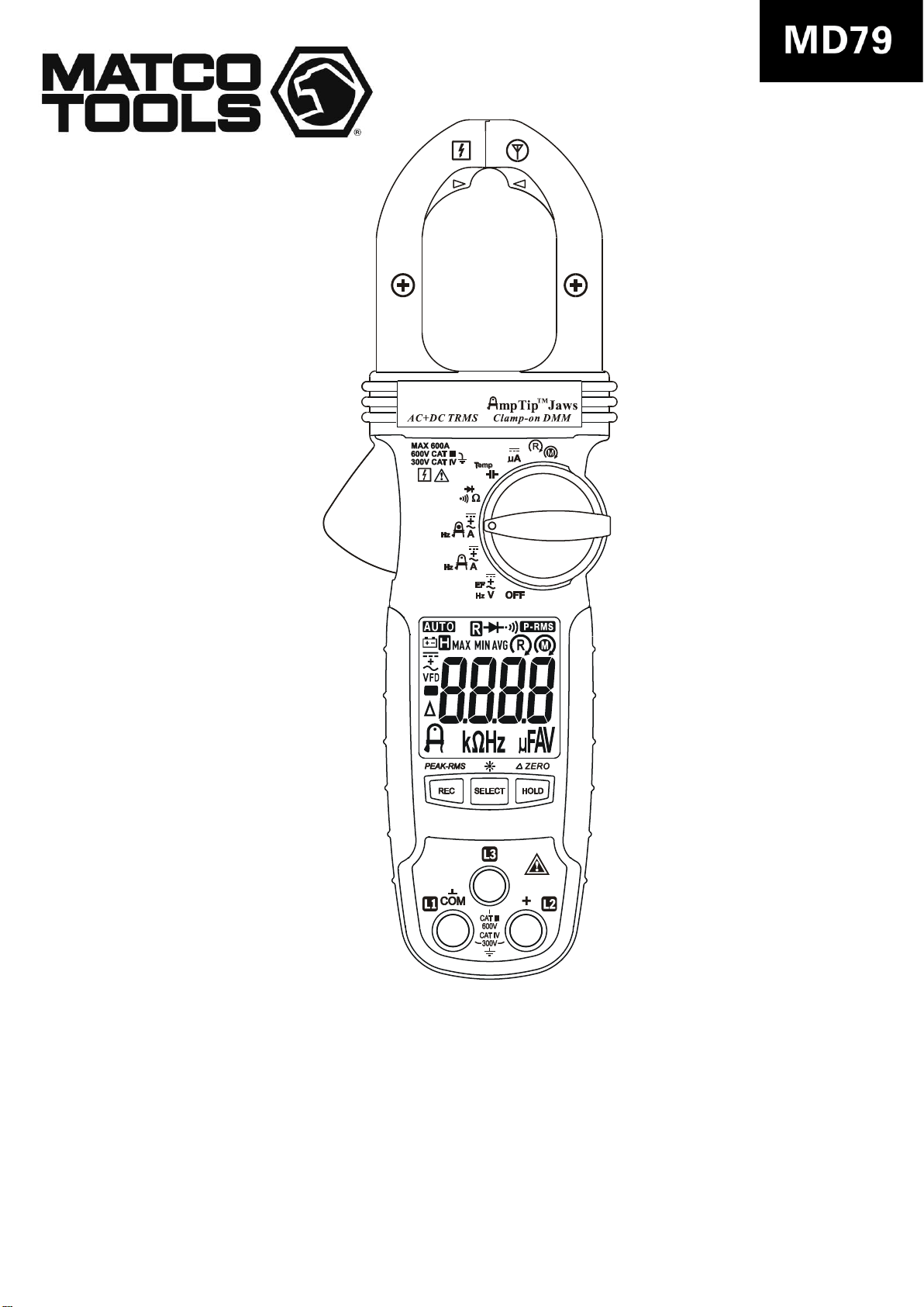
MD79 AC+DC
Clamp-on Multimeter

1
1) SAFETY
This manual contains information and warnings that must be followed
for operating the instrument safely and maintaining the instrument in a
safe operating condition. If the instrument is used in a manner not
specified by the manufacturer, the protection provided by the
instrument may be impaired.
The meter protection rating, against the users, is double insulation per
UL/IEC/EN61010-1 Ed. 3.0, IEC/EN61010-2-033 Ed. 1.0, CAN/CSA
C22.2 No. 61010-1 Ed. 3.0, IEC/EN61010-2-032 Ed. 3.0 &
IEC/EN61010-031 Ed. 1.1:
Measurement Category III 600V & Category IV 300V AC & DC.
Per IEC61010-1 (2010) OVERVOLTAGE CATEGORY
OVERVOLTAGE CATEGORY ll (CAT II) is for equipment intended to
be supplied from the building wiring. It applies both to plug-connected
equipment and to PERMANENTLY CONNECTED EQUIPMENT.
OVERVOLTAGE CATEGORY lll (CAT III) is for equipment intended to
form part of a building wiring installation. Such equipment includes
socket outlets, fuse panels, and some MAINS installation control
equipment.
OVERVOLTAGE CATEGORY lV (CAT IV) is for equipment installed at
or near the origin of the electrical supply to a building, between the
building entrance and the main distribution board. Such equipment may
include electricity tariff meters and primary overcurrent protection
devices.
TERMS IN THIS MANUAL
WARNING identifies conditions and actions that could result in
serious injury or even death to the user.
CAUTION identifies conditions and actions that could cause damage
or malfunction in the instrument.

2
WARNING
To reduce the risk of fire or electric shock, do not expose this product to
rain or moisture. The meter is intended only for indoor use.
To avoid electrical shock hazard, observe the proper safety precautions
when working with voltages above 60 VDC or 30 VAC rms. These
voltage levels pose a potential shock hazard to the user. Before and
after hazardous voltage measurements, test the voltage function on a
known source such as line voltage to determine proper meter
functioning.
Keep your hands/fingers behind the hand/finger barriers (of the meter
and the test leads) that indicate the limits of safe access of the hand-
held part during measurement. Inspect test leads, connectors, and
probes for damaged insulation or exposed metal before using the
instrument. If any defects are found, replace them immediately. Only
use the test lead provided with the equipment or UL Listed Probe
Assembly rated CAT III 600V or better.
This Clamp-on meter is designed to apply around or remove from
uninsulated hazardous live conductors. But still, individual protective
equipment must be used if hazardous live parts in the installation where
measurement is to be carried out could be accessible.
CAUTION
Disconnect the test leads from the test points before changing meter
functions.
INTERNATIONAL ELECTRICAL SYMBOLS
!
Caution ! Refer to the explanation in this Manual
Caution ! Risk of electric shock
Earth (Ground)
Double Insulation or Reinforced insulation
Fuse
AC--Alternating Current
DC--Direct Current
Application around and removal from hazardous live conductors
is permitted
2) CENELEC Directives
The instruments conform to CENELEC Low-voltage directive
3
2006/95/EC and Electromagnetic compatibility directive 2004/108/EC
3) PRODUCT DESCRIPTION
This user's manual uses only representative model(s) for illustrations.
Please refer specification details for function availability to each model.
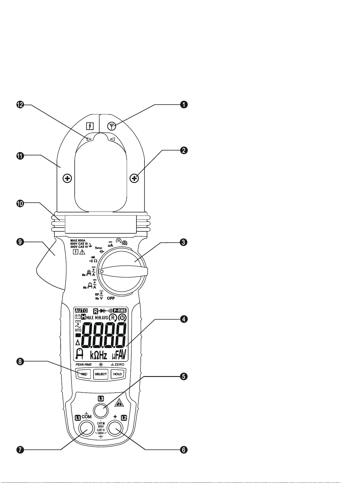
1) Antenna area for Non-Contact
EF-Detection
2) Jaw center indicator (with DCA
polarity for Models 079, 078 &
077), at where best current
accuracy is specified
3) Rotary Selector to turn the
power ON/OFF and Select a
function
4) 3-5/6 digits 6000 counts numeric
LCD display
5) Additional input Jack for Phase
Rotation function only
6) Input Jack for all functions
EXCEPT non-invasive DCA,
DC+ACA, or ACA current
functions
7) Common (Ground reference)
Input Jack for all functions
EXCEPT non-invasive DCA,
DC+ACA, or ACA current functions
8) Push-buttons for special
functions & features.
9) Jaw trigger for opening the
clamp jaw
10) Hand/Finger Barrier to indicate
the limits of safe access of the
meter
11) Clamp Jaw for DC or AC
current magnetic field pick up
12) Additional center indicator for
AmpTipTM Low-current function,
at where best AmpTipTM current
accuracy is specified
4
4) OPERATION
WARNING: Before and after hazardous voltage measurements, test
the voltage function on a known source such as line voltage to
determine proper meter functioning.
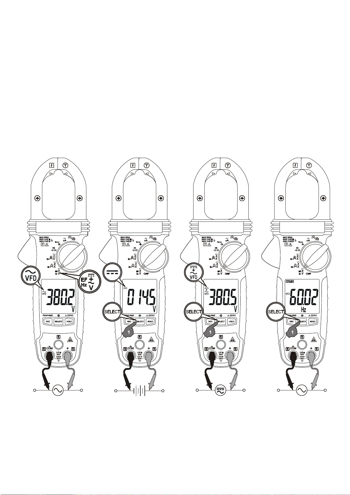
ACV, DCV, DC+ACV Line-level Hz, & EF (NCV) functions
Inputs, other than that of EF as described below, are made through the
test lead terminals COM/+. Defaults at ACV* Function. Press SELECT
button momentarily to select DCV, DC+ACV, Line-level Hz or EF**
(NCV) function in sequence.
Note:
*ACV (and hence AC+DCV & Line-level Hz) function is equipped with
digital low-pass filter, and is capable of dealing with VFD (Variable
Frequency Drives) signals. It also improves ACV reading stability in
noisy electrical environments.

5
Electric Field EF-Detection
The meter displays “EF” when it is ready. Signal strength is indicated
as a series of bar-graph segments on the display together with variable
beep tones.
• Non-Contact EF-Detection: An antenna is located along the top-right end of the
stationary clamp jaw, which detects electric field surrounds energized conductors. It is
ideal for tracing live wiring connections, locating wiring breakage and to distinguish
between live or earth connections.
• Probe-Contact EF-Detection: For more precise indication of live wires, such as
distinguishing between Live and Ground connections, use one single probe to test via
terminal COM for direct contact EF-Detection with best sensitivity.

6
CAUTION & WARNING for Non-Invasive (Clamp-on) Current
Measurements:
CAUTION
(Application and Removal of the Clamp-on Jaws) For non-invasive
current measurements, press the jaw trigger and clamp the jaws
around conductor(s) of only one single pole of a circuit for load current
measurement. Make sure the jaws are completely closed, or else it will
introduce measurement errors. Enclosing conductor(s) of more than
one pole of a circuit may result in differential current (like identifying
leakage current) measurement. Align the conductor(s) to the Jaws
center indicators (Regular or AmpTip™ indicators where applicable) as
much as possible to get the best measuring accuracy. For removal,
press the jaw trigger and remove the jaws from the conductor(s).
Adjacent current-carrying devices such as transformers, motors and
conductor wires may affect measurement accuracy. Keep the jaws
away from them as much as possible to minimize influence.
WARNING
Do not use the meter to measure currents above the rated frequency
(400Hz). Circulating currents may cause the magnetic circuits of the
Jaws reach a hazardous temperature.
7
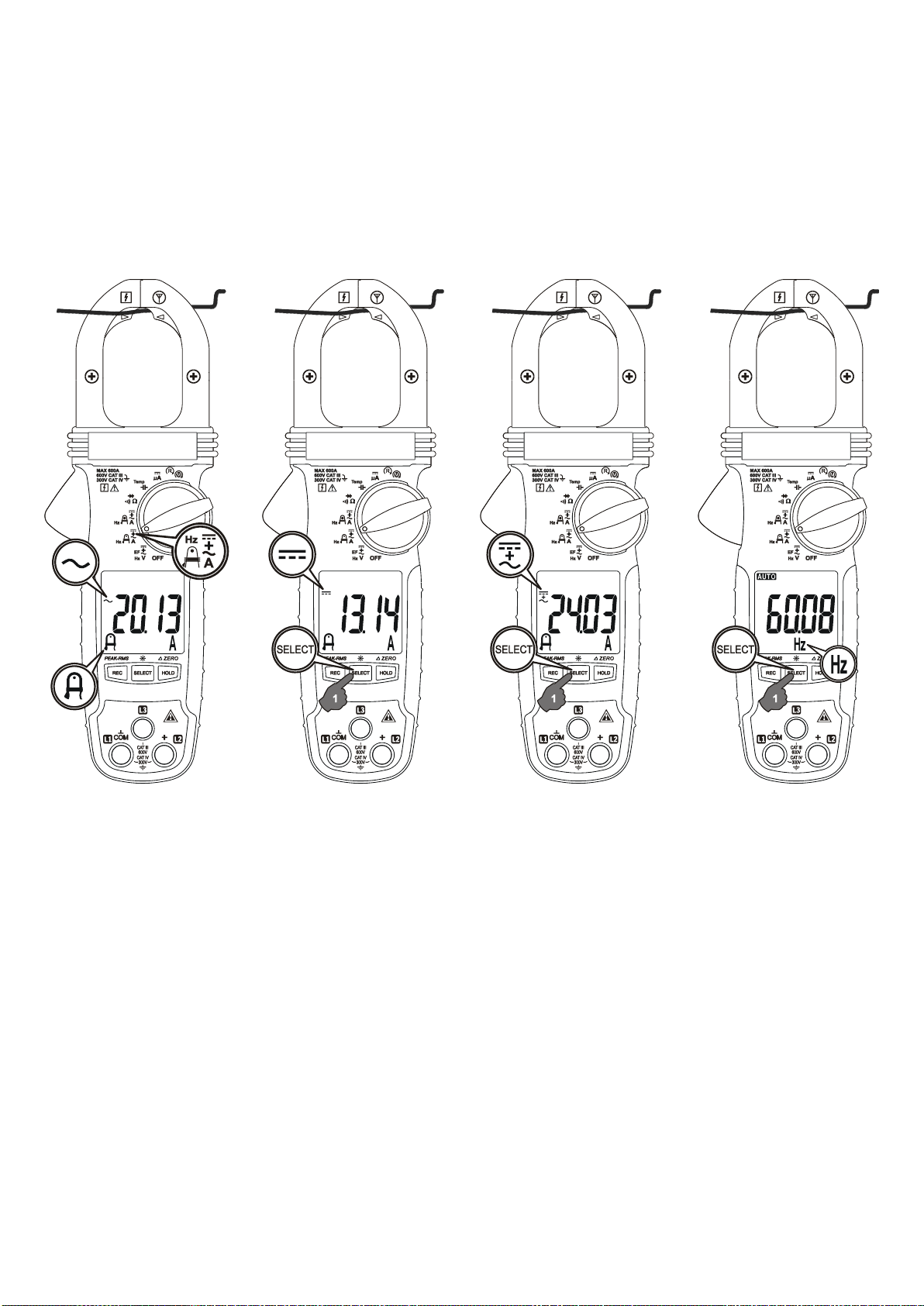
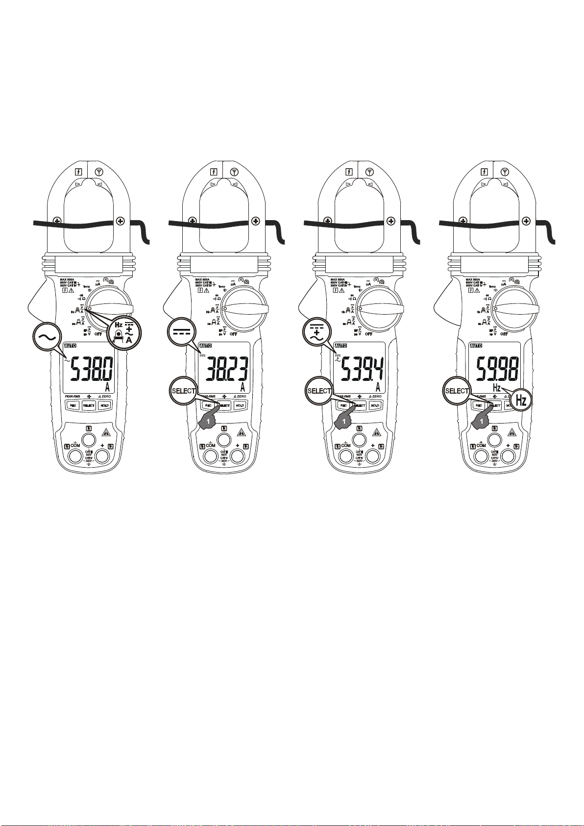
Non-Invasive AmpTipTM Low-Current Functions:
ACA, DCA, DC+ACA & Hz
Input is made via the clamp jaws with best accuracy specified near the
jaw tip area for small conductors low-current measurements. Defaults
at ACA function. Press SELECT button momentarily to select the
subject functions in sequence.
8
Non-Invasive Regular Current Funtions:
ACA, DCA, DC+ACA & Hz
Input is made via the clamp jaws with best accuracy specified at the
jaw center for regular current measurements. Press SELECT button
momentarily to select the subject functions in sequence.
9
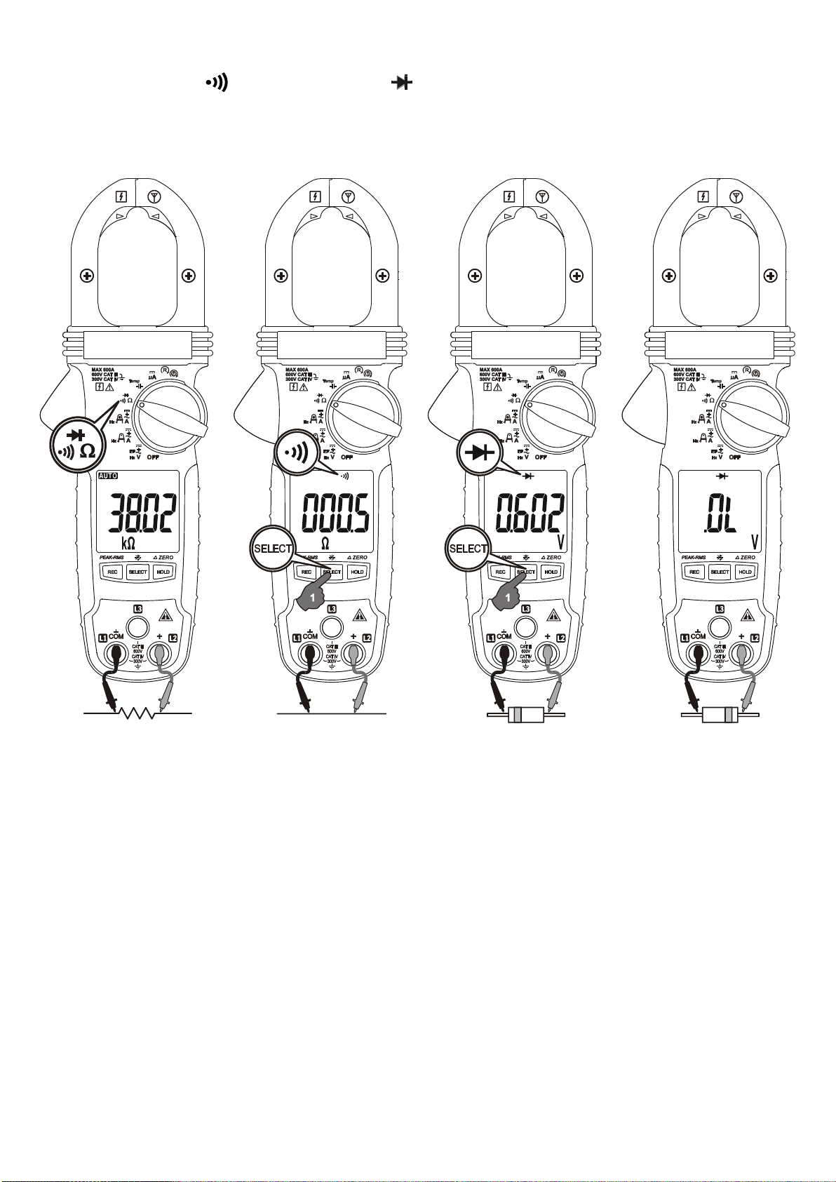
Resistance, Continuity, & Diode functions
Inputs are made through the test lead terminals COM/+. Defaults at
Resistance. Press SELECT button momentarily to select the subject
functions in sequence.
Note
When using Diode test function, normal forward voltage drop (forward biased) for a
good silicon diode is between 0.400V to 0.900V. A reading higher than that indicates a
leaky diode (defective). A zero reading indicates a shorted diode (defective). An OL
indicates an open diode (defective). Reverse the test leads connections (reverse
biased) across the diode. The digital display shows OL if the diode is good. Any other
readings indicate the diode is resistive or shorted (defective).
CAUTION
Using Resistance, Continuity or Diode function in a live circuit will produce false results
and may damage the meter. In many cases, the suspected component(s) must be
disconnected from the circuit to obtain an accurate measurement reading.
Table of contents
Languages:
Other Matco Tools Multimeter manuals


Popular Multimeter manuals by other brands


Gossen MetraWatt
Gossen MetraWatt METRAmax 6 operating instructions

PeakTech
PeakTech 4000 Procedure of calibration

YOKOGAWA
YOKOGAWA 90050B user manual

Gossen MetraWatt
Gossen MetraWatt METRALINE DMM16 operating instructions

Fluke
Fluke 8846A Programmer's manual

Tempo Communications
Tempo Communications MM200 instruction manual


