matev SWE-SD 140 JD Installation instructions

matev GmbH
Nürnberger Str. 50
90579 Langenzenn
T +49 (0) 9101 9087 -0
F +49 (0) 9101 9087 -20
info@matev.eu
www.matev.eu
Version
03/2012
Original Operating Manual
Front sweeper SWE-SD 140 JD
131_7502

Table of contents
Page 2
Table of contents
1About this operating manual....................................................................................3
2Safety.........................................................................................................................3
2.1 Intended use...............................................................................................................3
2.2 Qualification of personnel............................................................................................4
2.3 General safety instructions..........................................................................................4
2.4 Special safety instructions...........................................................................................5
3Task and use.............................................................................................................6
4Installation of the front sweeper ..............................................................................6
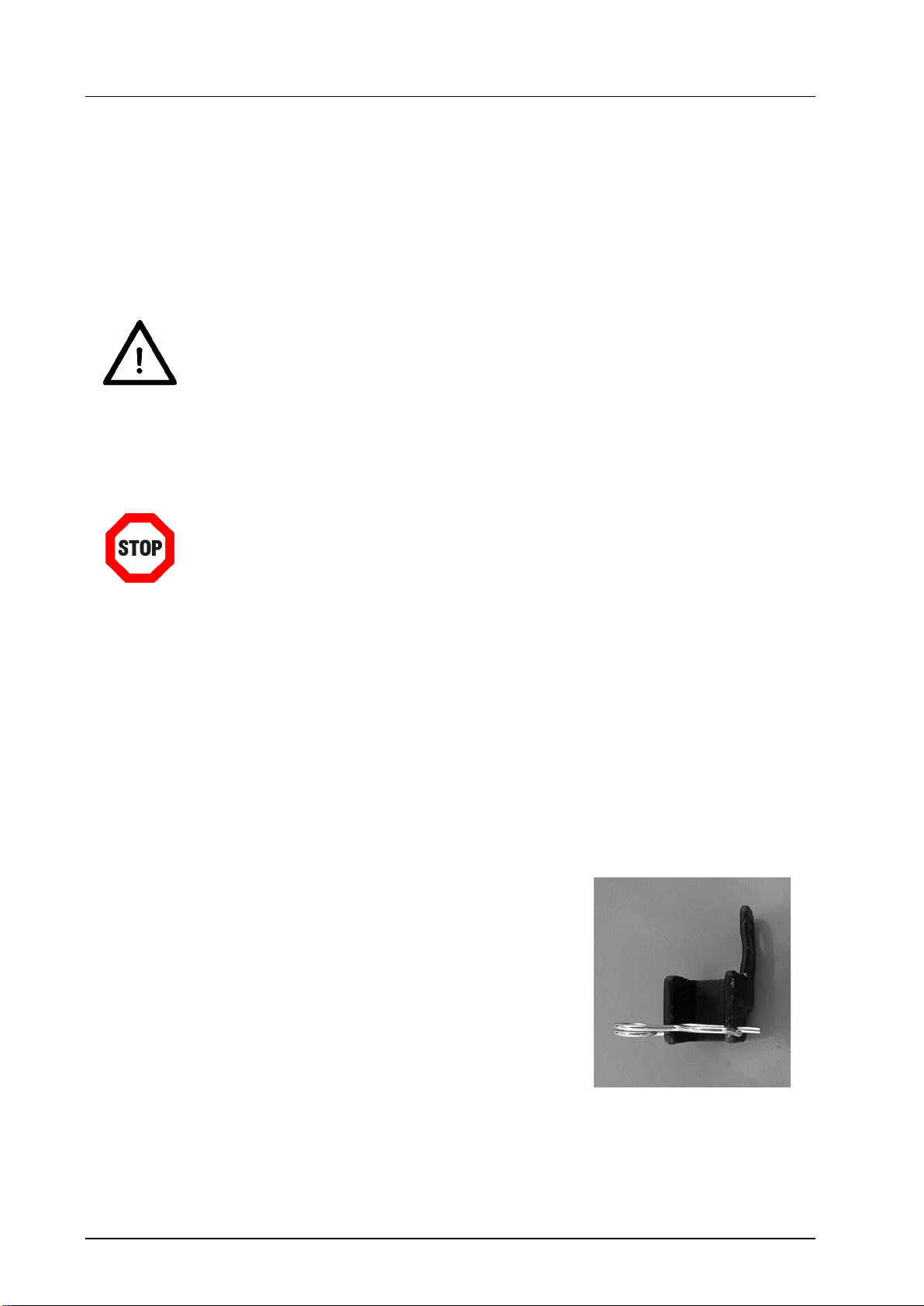
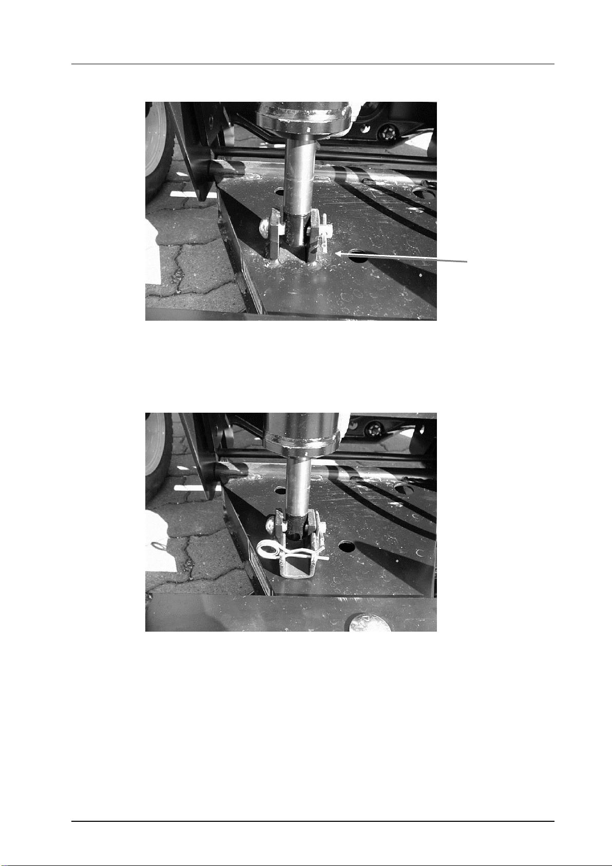
4.1 Preparation on the lift cylinder.....................................................................................6
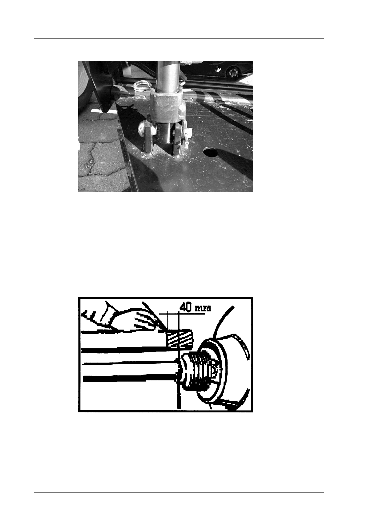
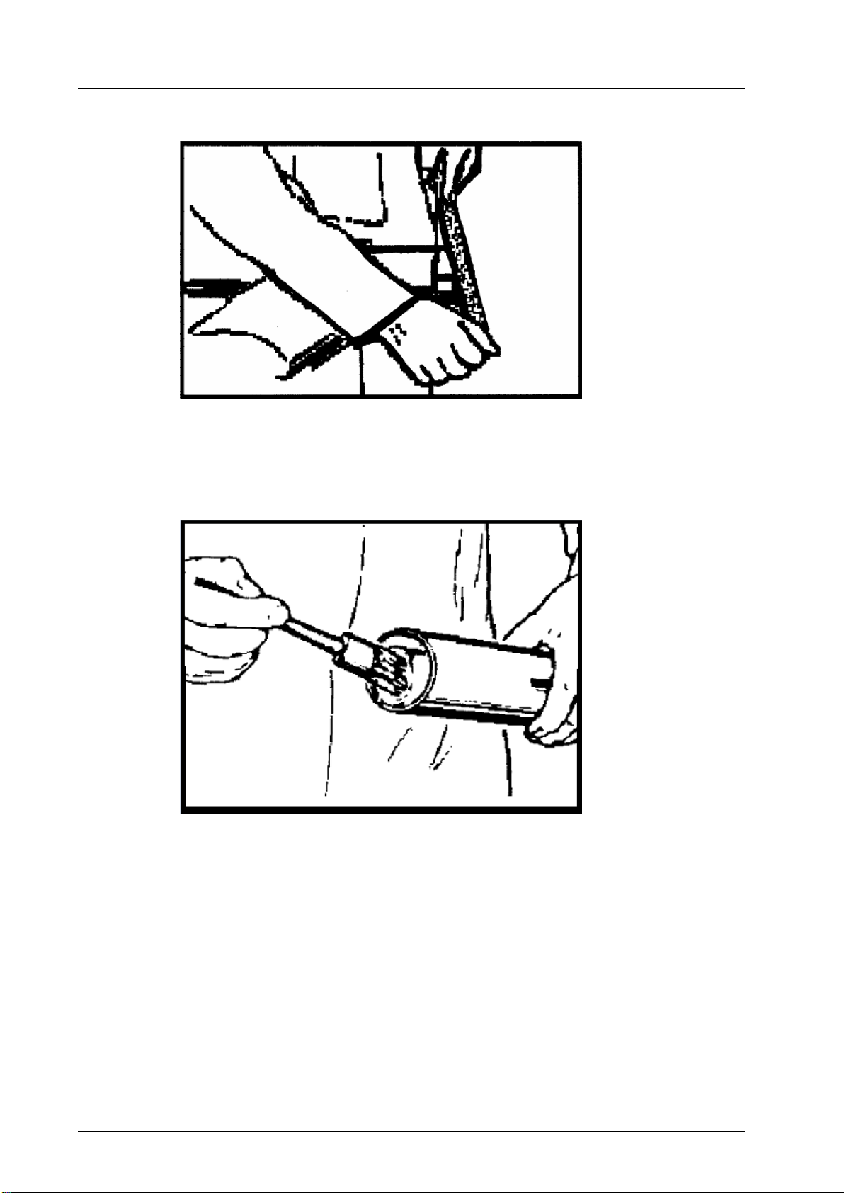
4.1.1 Shortening the universal joint shaft .............................................................................8
4.1.2 Mounting the universal joint shaft..............................................................................10
4.1.3 Attach the front sweeper...........................................................................................12
4.2 Removing the front sweeper .....................................................................................13
4.3 Mounting the refuse container...................................................................................13
5Operation.................................................................................................................15
5.1 Working with the front sweeper.................................................................................15
5.1.1 Lifting, lowering, and pivoting the front sweeper........................................................16
5.1.2 Sweeping with the refuse container...........................................................................16
5.1.3 Sweeping without the refuse container......................................................................16
5.1.4 Emptying the refuse container...................................................................................17
5.2 Adjusting the wheel height ........................................................................................17
6Maintenance............................................................................................................18
6.1 General.....................................................................................................................18
6.2 Maintenance .............................................................................................................18
6.2.1 Maintenance after 25 operating hours or after a longer standstill period....................18
6.2.2 Replacing the sweeper roller.....................................................................................18
6.2.3 Adjusting the belt ......................................................................................................20
6.3 Repair.......................................................................................................................21
7Disposal...................................................................................................................21
8Guarantee................................................................................................................21
9Technical data and accessories.............................................................................21
9.1 Technical data...........................................................................................................21
9.2 Accessories and spare parts.....................................................................................22
10 List of illustrations..................................................................................................22
11 EC Declaration of Conformity ................................................................................23

Contents
Page 3
1 About this operating manual
Dear customer!
Thank you for purchasing this front sweeper, we appreciate your trust.
Prior to using this implement for the first time, read this operating manual carefully and
conscientiously all the way through.
Keep this operating manual where it is easily accessible. This will enable you to refer to
important information and handling instructions as needed.
Listings with bullet points are marked as follows:
Text
Text
Text . . .
Handling instructions are marked in the sequence in which they should be executed, as
follows:
1. Text
2. Text
3. Text . . .
This front sweeper is subject to change in the interest of technical progress.
All information, illustrations, and technical specifications represent the lat-
est status at the time this manual was published. The manufacturer reserves
the right to make changes at any time in the interest of technical progress.
2 Safety
Guidelines and instructions with which you must comply, are summarized in this section.
Persons who install, operate and mount the front sweeper must have read and under-
stood this operating manual.
2.1 Intended use
The front sweeper should only be mounted and operated on tractors with original John
Deere two-point front lift.
All other uses are excluded.
In addition, compliance with the service and maintenance guidelines is a component of
intended use. Moreover intended use includes exclusive use of original spare parts and
supplemental equipment, or use of such parts and equipment that meet the technical re-
quirements specified by the manufacturer.
Non-intended use causes:
Health hazards for the operator or for third parties
Damage to the tractor and the implements
Immediate invalidation of the guarantee
Environmental damage
To avoid accidents and to reduce the risk of accidents, the relevant accident prevention
regulations and the other generally acknowledged occupational health and safety and
road traffic regulations apply without limitation.

Safety
Page 4
Changes to the front power system and/or the associated accessories invalidate the
guarantee and exclude any liability on the part of the manufacturer for damage due to the
changes.
2.2 Qualification of personnel
Only persons 18 years of age or older, or instructed persons should install, operate, and
maintain the front sweeper. The operator must have read and understood this operating
manual.
2.3 General safety instructions
General safety instructions are explained in this section. These safety instructions are
used in the subsequent sections. In addition to the safety aspect, you will save money
and work time if you follow these safety instructions.
Danger!
Severe injury to the operator or third parties occurs.
Follow the safety instruction.
Attention!
Minor injury to the operator or third parties can
occur. The tractor, the grass bagger, or the environment can be damaged.
Comply with the safety instruction.
Note!
Important, helpful tips or information for the operator.
Read this note. It facilitates your work.
Attention!
Injuries can occur.
Wear protective work clothing.

Contents
Page 5
2.4 Special safety instructions
Safety instructions are specified in this chapter that are also affixed as stickers on the im-
plements.
Attention!
Danger of injury due to moving parts.
Remove the ignition key before performing maintenance tasks on the im-
plement.
Attention!
Danger of injury due to rotating parts.
Switch off the implement. Wait until all machine parts have come to a stand-
still before converting or servicing the implement.
Attention!
Injuries can occur due to improper operation. The implement can be dam-
aged.
Read the operating manual all the way through.
Comply with the safety instructions.
Attention!
Danger of crushing due to moving parts.
Never reach into the crushing hazard danger area, if parts are still moving or
can move.
Comply with the instruction in the operating manual.
Attention!
There is an increased risk of accident due to the rotating PTO shaft.
Do not enter the work area of the PTO shaft when it is rotating.
For your own safety do not wear any loose clothing, belts, on any other
loose items.
Attention!
Check all threaded unions prior to using the implement and after using the
implement. Loosened connections must be retightened.
Damage can occur due to loose connections.

EC Declaration of Conformity
Page 6
3 Task and use
The front sweeper is used to sweep dirt. In the standard version without refuse container
the dirt is swept free to the side. The optionally available refuse container enables collec-
tion of the dirt when sweeping.
The front sweeper may be used to sweep snow. However you must comply with the fol-
lowing points:
Attention!
The front sweeper can be damaged.
Do not use the front sweeper with the optionally available refuse container.
The sweeper should only be used for low quantities of snow, to approx. 5
cm.
4 Installation of the front sweeper
Danger!
Severe injury to the operator or third parties occurs.
Switch off the tractor and remove the ignition key before mounting or dis-
mounting the implements.
Note!
Enter the vehicle chassis number of the front sweeper in section 6.3 of this
operating manual.
Note!
Only mount the front sweeper on the original front lift from John Deere.
4.1 Preparation on the lift cylinder

List of illustrations
Page 7
Fig. 1 Lift limiter for cylinder
1. Remove the spring cotter pin of the bolt of the cylinder.
Fig. 2 Lift limiter mounted on the cylinder bolt
2. Fit the lug of the lift limiter onto the bolt on the cylinder.
3. Secure the lock bolt with the spring cotter pin.
Spring cotter pin

EC Declaration of Conformity
Page 8
Fig. 3 The front power system is prepared for use of the front sweeper.
4. Pull the spring cotter pin out of the lift limiter.
5. Flip up the lift limiter.
6. Secure the lift limiter with the spring cotter pin.
Instructions for shortening and mounting the universal joint shaft
4.1.1 Shortening the universal joint shaft
1. Pull the two halves of the universal joint shaft apart.
2. Mount one end of the universal joint shaft on the tractor frame.
3. Mount the other end of the universal joint shaft on the implement.
Fig. 4 In the shortest work position, mark the piece that will be sawn off on one half of the
universal joint shaft.

List of illustrations
Page 9
4. Cut off the universal joint shaft guard to the marking. (Figure 5)
Fig. 5 Cut off the universal joint shaft
5. Saw off the profile tube. Attention: The profile tube must be 10 mm longer than the
guard. (Figure 6)
Fig. 6 Saw off the profile tube
6. Repeat steps 4 to 6 on the other half of the universal joint shaft.
7. Debur all sawn edges.

EC Declaration of Conformity
Page 10
Fig. 7 Debur all sawn edges
8. Grease the profile tubes
Fig. 8 Grease the profile tubes
9. Slide the profile tubes together.
4.1.2 Mounting the universal joint shaft
10. Press the locking pin on the outer forks and keep it depressed.
11. Slide the outer fork onto the profile stub of the front PTO shaft.
12. Release the locking pin.

List of illustrations
Page 11
13. Slightly move the universal joint shaft back and forth until the locking pin audibly
locks in place.
Fig. 9 Slightly move the universal joint shaft back and forth
14. Hook the universal joint shaft safety chains to a stationary part on the tractor and on
implement.
Depending on the version the machines are equipped with a hydraulic swivel device.
Plug the hydraulic hoses in the hydraulic sockets on the tractor provided for this purpose.
Attention!
Ensure that the plug-in couplings are clean.

EC Declaration of Conformity
Page 12
4.1.3 Attach the front sweeper
Fig. 10 Attach the front sweeper
1. Carefully drive the tractor to the front sweeper.
2. Switch off the tractor and remove the ignition key.
3. Pull out the locking pins and turn the vertically to arrest them.
Fig. 11 Front sweeper hooked in
4. Check whether the lift limiter is mounted and flipped up.
5. Hook the front sweeper into the front lift.
Locking pins
locked
Lift limiter
Locking pins
unlocked

List of illustrations
Page 13
6. Turn the locking pins on both sides horizontally until they engage.
7. Connect the PTO shaft to the tractor.
4.2 Removing the front sweeper
1. Dismount the PTO shaft on the tractor.
2. Pull out the locking pins on both sides and turn them vertically to arrest them.
3. Lift the front sweeper out of the front lift.
4. In addition, firmly hold the PTO shaft.
5. Slide the front sweeper forward, away from the tractor.
When you are not using the front sweeper flip the lift limiter on the cylinder downward.
Fig. 12 Lift limiter flipped down
6. Pull the spring cotter pin out of the lift limiter.
7. Flip the fixture downward.
8. Insert the spring cotter pin into the lift limiter.
4.3 Mounting the refuse container
Note!
The refuse container is an accessory and is not included in the scope of
delivery of the front sweeper. Order the refuse container separately.
Spring cotter pin

EC Declaration of Conformity
Page 14
Fig. 13 Preparations on the front sweeper
1. Fasten the provided lugs and spacers in the bores provided on both sides of the
front sweeper
Fig. 14 Hooking in the refuse container
2. Hold the refuse container on the lugs.
3. Slide the bolts through the bores.
4. Secure the bolts with the linch pins.
Spacer
Shackle

List of illustrations
Page 15
Fig. 15 Refuse container mounted
5. Adjust the spacers so that the contact wheel on the refuse container barely touches
the ground in work position.
5 Operation
Attention!
Before starting up the implement, read the instructions on safety and han-
dling for operation of the entire implement and connection to the tractor.
5.1 Working with the front sweeper
Attention!
The front sweeper can be damaged. Before each use, check the adjustment
of the support wheels, see section 5.2 in this regard.
Operate the front sweeper from the driver’s seat of the tractor.
Spacer

EC Declaration of Conformity
Page 16
5.1.1 Lifting, lowering, and pivoting the front sweeper
Fig. 16 Control levers
1. Activate the lower control lever for lifting and lowering the front sweeper.
2. Activate the upper control lever for pivoting the front sweeper.
5.1.2 Sweeping with the refuse container
1. With the angle adjustment element, adjust the front sweeper so that it is transverse
to the direction of travel.
2. Lower the front sweeper.
3. Switch the hydraulics to the float setting.
4. Switch on the front PTO shaft on the tractor, the sweeper roller will turn.
5. Drive forward at a slow speed.
5.1.3 Sweeping without the refuse container
Attention!
Third persons can be injured and objects can be damaged. When free
sweeping, i.e. without the refuse container, rocks or similar objects can be
accelerated forward by the sweeper roller. Consequently always maintain an
adequate distance to persons who could be injured or objects that could be
damaged.
The manufacture accepts no liability in such cases injury or damage.
1. With the angle adjustment element, adjust the front sweeper to he desired diagonal
position.
2. Lower the front sweeper.
3. Switch the hydraulics to the float setting.
Pivoting
lifting,
lowering

List of illustrations
Page 17
4. Switch on the front PTO shaft on the John Deere, the sweeper roller will turn.
5. Drive forward at a slow speed.
5.1.4 Emptying the refuse container
Fig. 17 Emptying the refuse container
1. Drive to the unload point.
2. Grasp the handle of the refuse container.
3. Swing the refuse container upward.
The refuse falls out.
5.2 Adjusting the wheel height
Note!
Adjust the support wheels so that the sweeper roller lightly touches the
ground in work position.
Handle

EC Declaration of Conformity
Page 18
Fig. 18 Adjusting the wheel height
1. Pull out the linch pin.
2. Change the position of the spacer bushes depending on the desired height.
3. Secure the wheel with the linch pin.
4. Adjust the same height on the second wheel.
6 Maintenance
6.1 General
Attention!
Personal injury or damage to the tractor and the implements can occur.
Before each use of the implements check all safety-relevant parts, and the
hydraulic connections.
6.2 Maintenance
6.2.1 Maintenance after 25 operating hours or after a longer standstill period
At regular intervals, and always at the beginning and end of the season, the moving parts
of the implement must be greased or oiled.
6.2.2 Replacing the sweeper roller
Note!
Always replace both sweeper rollers.
Linch pin
Spacer bushes

List of illustrations
Page 19
The following tasks must be executed on both sides of the sweeper roller.
Fig. 19 Sweeper roller
5. Unscrew the grub screw on the bearing tension ring.
Fig. 20 Tension ring
6. Detach the tension ring through a light blow (with drift punch) counter-clockwise.
7. Remove the fastening screws of the side bearing.
8. Remove the side bearing.
9. Remove bearing sleeve from the threaded rod.
10. Pull off the sweeper roller from the side.
11. Fit on the new sweeper roller.
Fastening
screws
Bearing tension ring
Drift punch
Tension ring

EC Declaration of Conformity
Page 20
12. Mount the side bearing.
13. Fasten the tension ring through a light blow (with drift punch) clockwise.
14. Replace the second sweeper roller.
6.2.3 Adjusting the belt
Fig. 21 Cover plate removed
1. Remove the cover plate.
Fig. 22 Adjusting the belt
2. Unscrew the fastening screws on the gearbox.
3. Tension the belt with the adjusting screws.
4. Firmly tighten the fastening screws on the gearbox.
5. Mount the cover plate.
Set screw
Fastening screw
This manual suits for next models
1
Table of contents
Other matev Blower manuals
Popular Blower manuals by other brands

Showven
Showven uFetti Blower user manual

Bissell
Bissell Perfect sweep turbo 2880 SERIES user guide

Cocraft
Cocraft CLR01-R3-42 Original instructions

Firmhorn
Firmhorn Avenue ECO power Original operating instructions

Craftsman
Craftsman INCREDI.PULL 316.794000 Operator's manual

Flymo
Flymo Power Vac 3000 Operator's manual