matev SWE-45 User manual

matev GmbH
Nürnberger Str. 50
90579 Langenzenn
T +49 (0) 9101 9087 -0
F +49 (0) 9101 9087 -20
www.matev.eu
Version: 04/2017
Operating Manual
SWE-45
Front sweeper

Contents
Page 2
Table of Contents
1About this Operating Manual...................................................................................................................3
2Safety.........................................................................................................................................................4
2.1 Intended Use..............................................................................................................................................4
2.2 Qualification of Personnel...........................................................................................................................4
2.3 General Safety Instructions ........................................................................................................................5
2.4 Special Safety Instructions .........................................................................................................................6
2.5 Basic Rules.................................................................................................................................................7
3Task and Application ...............................................................................................................................7
4Delivery and Shipment.............................................................................................................................8
5Installation.................................................................................................................................................8
5.1 Install Adapter Extension............................................................................................................................8
5.2 Mount Extension Cat or Extension JD........................................................................................................9
5.3 Assembly of the Drive Shaft for Sweepers with Mechanical Drive............................................................10
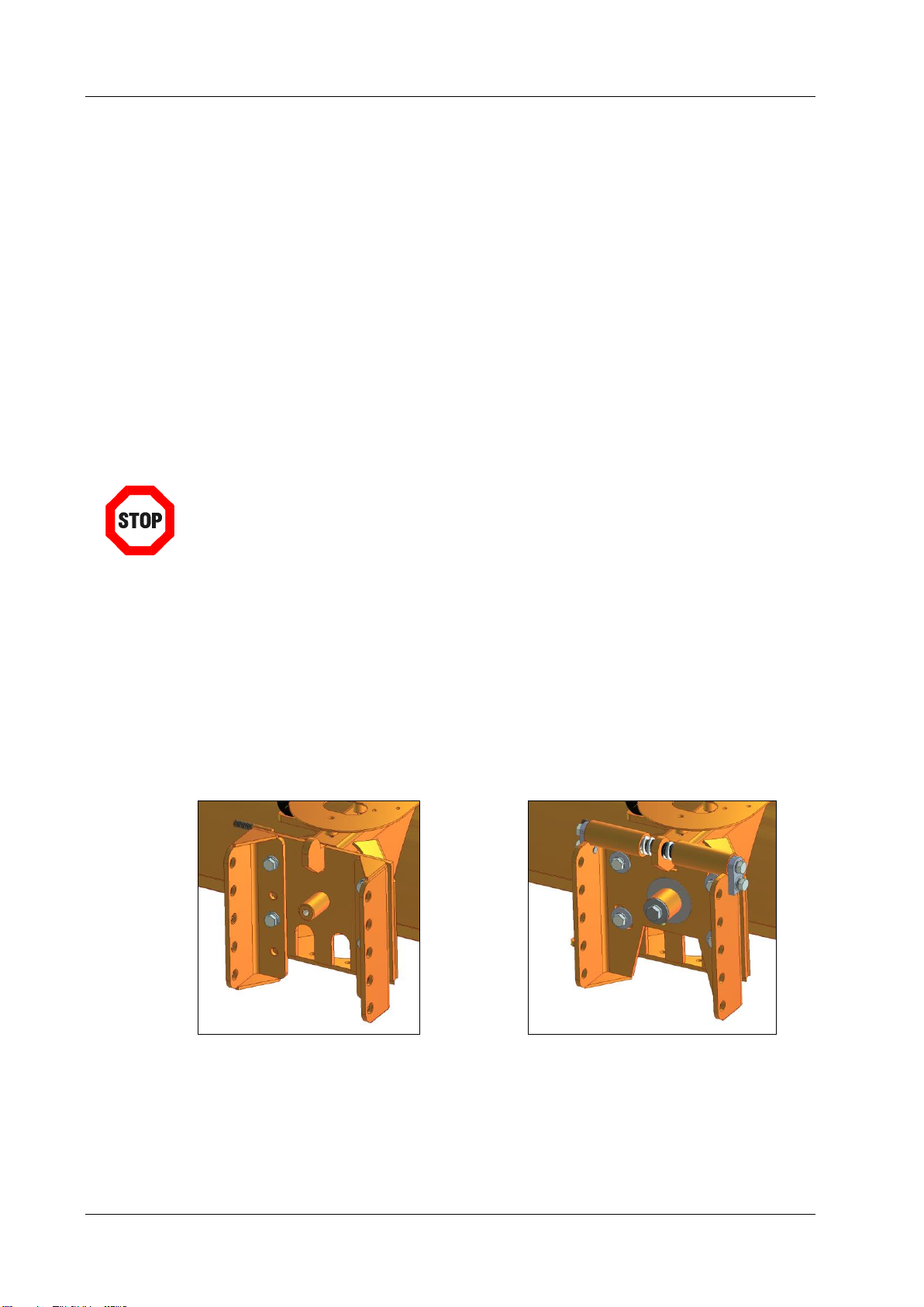
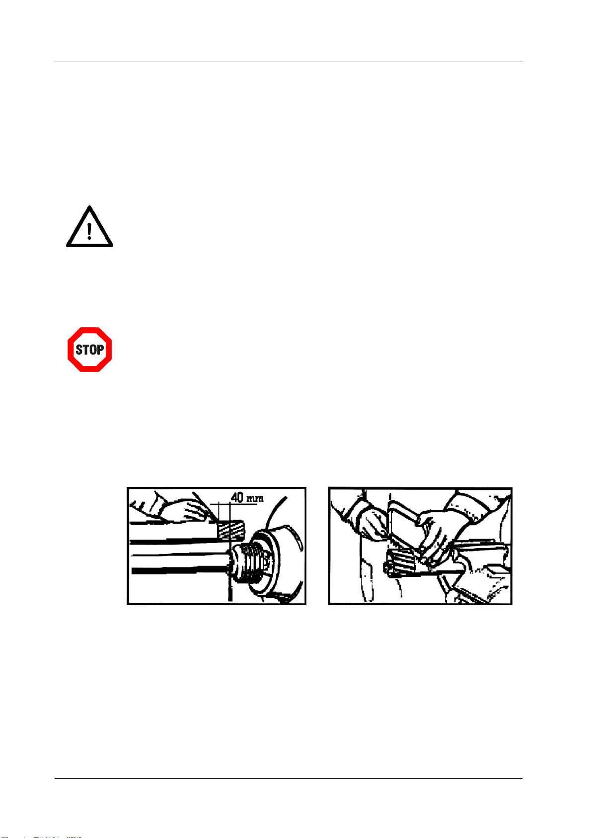
5.3.1 Adjusting the drive shaft ...........................................................................................................................10
5.3.2 Installing the drive shaft............................................................................................................................11
5.3.3 Drive shaft angled sharply........................................................................................................................12
5.4 Connect hydraulic connections of the sweeper to the tractor...................................................................12
5.5 Install the Dirt Catcher..............................................................................................................................13
5.6 Mount Splash Guard and Splash Plate.....................................................................................................16
5.7 Mechanically Assemble the Side Brush....................................................................................................17
5.8 Hydraulically Assemble the Side Brush....................................................................................................18
5.9 Installing the Irrigation Sprinkler ...............................................................................................................18
5.10 Electro-Magnetic Switching Valve ............................................................................................................19
5.11 Hydraulic Add-on Kit for Side Brush.........................................................................................................20
6Operation.................................................................................................................................................23
6.1 Adjust the sweeper...................................................................................................................................24
6.2 Parking the sweeper.................................................................................................................................26
6.3 Working with the Front Sweeper...............................................................................................................27
6.4 Exchange Sweeping Roller Edging ..........................................................................................................27
6.5 Rotation Speed.........................................................................................................................................28
6.6 Side Brush Mechanical and Hydraulic......................................................................................................29
6.6.1 Shift the support foot ................................................................................................................................29
6.6.2 Lift up side brush......................................................................................................................................29
7Maintenance............................................................................................................................................30
7.1 General Information..................................................................................................................................30
7.2 Maintenance.............................................................................................................................................30
7.2.1 Maintenance schedule..............................................................................................................................31
7.2.2 Lubrication schedule.................................................................................................................................31
7.2.3 Change sweeping roller............................................................................................................................32
7.3 Errors........................................................................................................................................................33
7.4 Repairs.....................................................................................................................................................33
8Disposal ..................................................................................................................................................33
9Guarantee................................................................................................................................................34
10 Technical data, Extension units and add-on kits.................................................................................34
10.1 SWE-H/M 12-45 .......................................................................................................................................34
10.2 SWE-H/M 14-45 .......................................................................................................................................34
10.3 SWE-H/M 16-45 .......................................................................................................................................34
10.4 Extension Units and Additional Equipment...............................................................................................35
11 Table of Figures......................................................................................................................................36
12 EC –Declaration of Conformity.............................................................................................................37

About this Operating Manual
Page 3
1 About this Operating Manual
Dear Customer,
We thank you for purchasing this front sweeper and the trust that you have put in us.
Before the machine's first operation, please read this Operating Manual completely and
thoroughly.
Keep this Operating Manual handy so that it is easily accessible. You can then refer to
important information and handling instructions as and when required.
Enumerations are marked with bullets as follows:
Text
Text
Text
Handling instructions are given in the sequence in which they need to be carried out,
marked as follows:
1. Text
2. Text
3. Text
The front sweeper is subject to technical progress. All information, figures
and technical specifications conform to the latest version at the time of
publication. The manufacturer reserves the right to make modifications at
any time in the context of technical developments.

Safety
Page 4
2 Safety
Note
It is absolutely necessary to read this!!!
Regulations and instructions that you need to observe and follow are summarised in this
chapter.
People who install, operate and maintain the front sweeper have to read and understand
this Operating Manual.
2.1 Intended Use
This machine has been built for the normal use of street and pavement cleaning, the
care of green areas and parks and winter road maintenance only.
Any use which goes beyond this definition shall be deemed as not as intended. The
manufacturer is not liable for any loss or damage resulting from this, and the
operator alone shall be responsible for any such risk.
Intended use also includes compliance with the conditions specified by the
manufacturer for operation, maintenance and service.
Each extension unit may only be operated, maintained and repaired by people who
are familiar with it and have been made aware of the dangers.
The intended use also implies that exclusively original –replacement parts and add-
on equipment and such parts and equipment is used which corresponds to the
technical specifications of the manufacturer.
Unauthorised alterations of the machine immediately lead to liability exclusion for the
manufacturer. The resulting damages of the unintended use can lead to the
following:
Risks to the health of the operator or third persons
Damage to the tractor or other devices mounted on it
Environmental damage
Immediate lapse of the guarantee
Alterations of the machine and/or its accessories which are not authorised by the
manufacturer lead to a lapse of the guarantee and exclude the manufacturer from
liability for damages which are a result of these alterations.
To avoid accidents and reduce the risks of accidents, the relevant accident
prevention guidelines and all other generally accepted safety, occupational medical
and traffic regulations must be adhered to.
2.2 Qualification of Personnel
Only such persons should install, operate and maintain the machine who are qualified as
follows:
They are at least 18 years of age.
They have read and understood this Operating Manual.

Safety
Page 5
2.3 General Safety Instructions
General information on safety is explained in this chapter and this is used in the
subsequent chapters.
Follow these safety instructions in order to ensure safe operation and to save working
time and costs.
Apart from the notes in this Operating Manual, note all generally accepted safety and
accident prevention regulations! Young people under the age 16 may not operate
this machine!
When using public roads, adhere to the respective regulations!
Before starting work, familiarise yourself with all equipment and operational elements
and their functions. Ensure that all protective devices are installed correctly.
The operator is responsible for third parties in the operating range!
Staying in the danger zone of the machine is prohibited!
Check the immediate vicinity before start-up. Ensure there is sufficient visibility!
When fluids (hydraulic oil) exit under high pressure, they can penetrate the skin and
cause severe injuries! Consult a doctor immediately –Danger of infection!
Repair, maintenance and cleaning works and the removal of malfunctions should
only be performed when the drive is switched off and the engine is at a standstill.
Remove ignition key! After performing this work, re-attach all safety devices!
When performing maintenance works on the lifted machine, always secure it with a
suitable support element!
These safety instructions are applied in the following chapters.
Danger!
The most severe injuries may occur to the operator or third persons.
Follow the safety instruction.
Attention!
Minor injuries may occur to the operator or third persons. The tractor, the
sweeper or the environment could be damaged. Note the safety instruction.
Note!
Important and helpful tips or information for the operator.
Please read this note. It simplifies your work.
Attention!
Injuries can occur.
Wear protective work gear.

Safety
Page 6
2.4 Special Safety Instructions
Safety instructions are listed in this section and are placed in the form of stickers on the
devices mounted.
Attention!
Injuries may occur as a result of unintended operation. This can damage the
machine.
Read the Operating Manual completely.
Follow the safety instructions.
Danger from moving parts when the engine is running –Keep a safe
distance.
Attention!
Risk of crushing by moving parts.
Never reach into the area posing a risk of crushing as long as there are
parts moving or could move there.
Follow the instruction in the Operating Manual.
Only touch machine parts when
they have reached a complete standstill.
Attention!
Before performing maintenance and repair works, switch off the engine and
remove the key. Risk of injury through moving parts.
Attention!
Risk of injury through turning parts. Switch off the machine. Wait until all
machine parts stop moving before you convert or maintain the equipment.
Do not stay within the range of the drive shaft.
Increased accident risk due to turning power take-off. Do not enter the
operating range of the power take-off when it is turning.
For your safety, do not wear loose clothing, straps or other loose things.
Be careful when high-pressure fluid exits.
Follow the instructions in the technical
handbook.
When the engine is running, never open
or remove safety devices.

Delivery and Shipment
Page 7
Attention!
Check all screw connections before and after each operation. Loose
connections must be tightened again.
Damages may occur.
2.5 Basic Rules
Before the machine is started up, check it for operational safety every time!!!
Cleaning work, such as cleaning with a high-pressure device, should be
performed so that the water jet is not pointed directly on bearing and turning
parts (shaft seals, grease nipples and so on). Otherwise check the free
movement of parts and grease, if necessary!
In the case of non-compliance, all guarantee claims lapse.
3 Task and Application
Combined with a tractor, the sweeper can be used to sweep dirt and snow on roads and
pavements. With an appropriate dirt catcher (available as an accessory), the swept-up
dirt can be caught at the same time.
This sweeper is an independently sweeping machine. This means the dirt is swept and
caught by the dirt catcher (accessory), if applicable. Because of this, you should expect a
certain dust development with this machine, unlike with a sweeping and suction machine.
The machine is installed at the front of a tractor and is driven from it through a power
take-off or a hydraulic engine. To sweep large areas, gutters or similar things, the
machine can be swivelled hydraulically in both directions.
All operation functions can be controlled from the driving seat.
Attention!
When sweeping snow, do not use the front sweeper with the available dirt
catcher. This can damage the front sweeper.
The sweeper may only be used for small levels of snow, up to about 5 cm.
Attention!
When using a dirt catcher and / or mechanical or hydraulic side brush
(available as an accessory), the sweeping roller cannot be swivelled. This
can damage the front sweeper.

Installation
Page 8
4 Delivery and Shipment
The sweeper is rigged to a pallet and delivered.
Lifting the sweeper from the pallet
1. Remove the protective packaging and the transport locks.
2. Lift the sweeper using suitable means (crane or forklift) from the pallet and put it down.
Transport over long distances
If you would like to transport the sweeper over longer distances (e.g. dispatch by
forwarding agency), you must rig the machine to a pallet as at the time of delivery.
5 Installation
Danger!
Switch the tractor off and pull out the ignition key before you assemble or
dismantle the devices mounted on it.
Note!
Enter the chassis number of the front sweeper in the 7.4 section of this
Operating Manual.
5.1 Install Adapter Extension
Depending on the chosen accessories, either an adapter extension rigid (Order No.
131_7733) or adapter extension swing balance (Order No. 131_7734) is mounted to the
basic model.
Figure 1: Adapter extension rigid Figure 2: Adapter extension Swing balance
Depending on the design of the front hydraulics, hang the front sweeper in the tractor
triangle or the two-point attachment. The first time, the adapter extension may have to be
adjusted depending on the desired lifting height.

Installation
Page 9
5.2 Mount Extension Cat or Extension JD
Attention!
Extension must be secured via bolts
To attach the sweeper, a tractor with coupling triangle or JD lift is required.
Adding the extension using a coupling triangle is done using either extension cat. 0 or
scanfram. When the quick coupling triangle is lifted into the extension, for safety reasons,
the locking bolt must be pushed in and secured by the spring plug. If this is not possible,
the locking part must be re-adjusted. Loosen both nuts of the locking part and move the
lock so that the bolt can be pushed in. Re-tighten the nuts after that.
Figure 3: Locking coupling triangle
The JD extension is added on using the JD lift mounted onto the tractor. The JD
extension can be tilted by moving the nuts on the eye-bolts parallel. The JD extension
must be adjusted so that the sweeper is horizontal when in use. The connection is
secured via two locking bolts.
Figure 4: Locking JD extension

Installation
Page 10
5.3 Assembly of the Drive Shaft for Sweepers with Mechanical Drive
A drive shaft or hydraulics are required to transfer power between the tractor and the
sweeper. Only use the drive shaft supplied by the manufacturer.
Depending on the tractor type, the drive shaft supplied may be too long. In this case, it
must be shortened in accordance with the following steps.
Attention!
Damages on the extension unit or tractor can occur.
Only use the supplied drive shaft.
Note!
When installing the drive shaft, also follow the supplied original instructions
of the drive shaft manufacturer.
The safety and maintenance instructions which are contained in the
Operating Manual supplied with the drive shaft have to be followed
absolutely!
5.3.1 Adjusting the drive shaft
1. Separate the drive shaft halves from one another.
2. Install one end of the drive shaft on the tractor.
3. Install the other end of the drive shaft on the extension unit.
4. At the shortest working position mark the piece to be sawed off on one half of the
drive shaft.
Figure 5: Marking the interface Figure 6: Sawing off the drive shaft
5. Cut off the drive shaft protective cover up to the marking.
6. Saw off the pipe section. Attention: the pipe section has to be 10mm longer than the
guard.

Installation
Page 11
Figure 7: Saw off the pipe section Figure 8: Deburr the edges
7. Repeat the instructions on the second half of the drive shaft.
8. Deburr all edges that have been cut.
9. Grease the pipe sections.
Figure 9: Greasing the section pipes
10. Push the section pipes together.
5.3.2 Installing the drive shaft
1. Push down the locking disc on the outer side and keep it pushed down.
2. Pull the splined hub on the splined shaft of the power take-off.
3. Release the locking disc.
4. Move the drive shaft somewhat to and fro until the locking disc latches audibly.
Figure 10: Latch in locking disc
5. Connect the counterpart of the shaft with the extension unit and secure it with the
screw contained in the delivery scope.
6. Mount the safety chains of the drive shaft to a fixed element on the tractor and on
the extension unit.

Installation
Page 12
5.3.3 Drive shaft angled sharply
Depending on the tractor, the drive shaft can be angled differently in the operating
position. If the drive shaft is angled too much, the service life is reduced. The angle of the
drive shaft can be reduced by extension (Order No. 131_7828).
Figure 11: Prolongation extension cat
5.4 Connect hydraulic connections of the sweeper to the tractor
Make sure the plug-in connectors are clean.
Hydraulic swivelling
The sweeper is equipped with a hydraulic swivelling unit. The two hydraulic hoses which
have to lead away from the swivel cylinder have to be connected to a free hydraulic cycle
on the tractor.
Hydraulic drive
If the sweeper is equipped with a hydraulic drive, the two hydraulic hoses (flow and
return) have to be connected to a free hydraulic cycle on the tractor. The litre capacity of
the cycle must suit the hydraulic engine.
If not enough hydraulic cycles are available on the tractor, an electro-magnetic switching
valve (Order No. 131_7746) is required.

Installation
Page 13
5.5 Install the Dirt Catcher
Note!
The dirt catcher is an accessory and is not part of the delivery scope of the
front sweeper. Order the dirt catcher separately.
1. The cylinder to swivel the sweeper is replaced through the connecting rod.
Figure 12: With cylinder Figure 13: With connecting rod
2. The cylinder holder and the lever is screwed onto the sweeper. The cylinder which is
used to swivel the sweeper is used to lift the dirt catcher.
Figure 14: Front sweeper with cylinder holder

Installation
Page 14
3. The screw-on bushing and counter plate to lift the dirt catcher must be installed as
shown in the pictures.
Figure 15: Screw-on bushing Figure 16: Counter plate screwed on
4. A screw M12x100 is screwed into the existing angle. The screw head is used as a
stop for the dirt catcher. By adjusting the screw, the dirt catcher is positioned.
Points 3 and 5 are performed on the left and right side of the sweeper.
5. The dirt catcher is connected together via the screw-on bushing and bolts. This step
is also done on both sides.
Figure 17: Pin sweeper and dirt catcher

Installation
Page 15
6. Hang up the adjusting rod into the dirt catcher.
Figure 18: Lifting mechanism
7. Adjust the dirt catcher via screw 12 and the adjusting rod so that the wheels of the
dirt catcher can roll on the floor.
8. Connect hydraulic hoses to the cylinder
Figure 19: Stop dirt catcher
Figure 20: Dirt catcher installed

Installation
Page 16
5.6 Mount Splash Guard and Splash Plate
Note!
The splash guard and splash plate are accessories and are not part of the
delivery scope of the front sweeper. Please order this separately.
The splash plate is assembled as shown in Figure 21.
Figure 21: Installation instruction splash plate
The splash guard is also assembled as shown in Figure 21. Additionally, the supplied
canvas is secured to the splash guard via a steel slat.
Figure 22: Sweeper with splash plate left, with splash gaurd right

Installation
Page 17
5.7 Mechanically Assemble the Side Brush
Note!
The side brush is an accessory and is not part of the delivery scope of the
front sweeper. Please order this separately.
The mechanical side brush is assembled as shown in Figure 23.
Figure 23: Installation instruction mechanical side brush

Installation
Page 18
5.8 Hydraulically Assemble the Side Brush
Note!
The hydraulic side brush is an accessory and is not part of the delivery
scope of the front sweeper. Please order this separately.
Figure 24: hydraulic side brush
If there is no free hydraulic cycle available on the tractor or the rotation speed of the side
brush is to be adjusted via a current regulation valve, a hydraulic add-on kit (Order No.
131_7739) is necessary.
5.9 Installing the Irrigation Sprinkler
Note!
The irrigation sprinkler is an accessory and is not part of the delivery scope
of the front sweeper. Please order this separately.
An additional operating manual is supplied for the irrigation sprinkler (Order No.
131_7704).
Figure 25: Irrigation sprinkler

Installation
Page 19
5.10 Electro-Magnetic Switching Valve
Note!
The electro-magnetic switching valve is an accessory and is not part of the
delivery scope of the front sweeper. Please order this separately.
The valve is mounted to the sweeper and hydraulically connected as shown in the
pictures. The letters in the pictures mark the ends of the hydraulic lines.
Figure 26: Electro-magnetic switching valve
Hydraulic lines consist of:
Line A: GE12L-1/2“; 1SN10-900-DKOL-DKOL90; GE12L-3/8“
Line B: GE12L-1/2“; 1SN10-700-DKOL-DKOL90: GE12L-3/8“
Line C: GE8L-3/8“; Adjustable angle 8L; 1SN06-DKOL-DKOL90; GE8L-1/4“
Line D: GE8L-3/8“; Adjustable angle 8L; 1SN06-DKOL-DKOL90; GE8L-1/4“

Installation
Page 20
The electro-magnetic switching valve is electrically connected as shown in the pictures.
Figure 27: Electrically connect the switching valve
Connect the supplied switch and plugs to the electronics of the tractor and install.
5.11 Hydraulic Add-on Kit for Side Brush
Note!
The hydraulic add-on kit for the side brush is an accessory and is not part of
the delivery scope of the front sweeper. Please order this separately.
The electro-magnetic switching valve is electrically connected as described in 5.10.
The valve is mounted to the sweeper and hydraulically connected as shown in the
pictures. The letters in the pictures mark the ends of the hydraulic lines.
Table of contents
Other matev Blower manuals