matev TRL-3D 20 User manual

matev GmbH
Nürnberger Str. 50
90579 Langenzenn
www.matev.eu
Version 2020-04
Installation Manual
Art. no. 131 8849
Chassis TRL-3D 20

Important notices
Page 2
1Important notices
1.1 Personnel qualification
Installation of safety-related components such as chassis (e.g. axles, wheel sus-
pensions, wheels, etc.), towing and lifting components (drawbars, three-point
hitches, front hydraulic lifts, intermediate axle lifts), brakes, etc. may be carried
out only by personnel with the following qualifications:
•They must have specialized training, for example as an agricultural mechanic
or auto mechanic, etc.
•Personnel without qualified training must be supervised by an employee with
qualified training.
•They must have read and understood this installation manual.
•They must be familiar with the relevant safety regulations (accident preven-
tion).
1.2 Accident prevention
Safety and accident prevention regulations are governed by the laws of each
country. The shop foreman or the assigned occupational safety and health spe-
cialist of the company carrying out the work is responsible for compliance with the
applicable regulations.
1.3 Symbols used
Use suitable means to ensure that the equipment is in a safe position for
installation.
The illustrations in this manual are provided only as an example. They
cannot be used to define a safe installation position.
Remove the assembly aids.
The assembly steps are explained in the referenced documentation. If this
documentation is not available to you, please contact matev GmbH.
Assembly steps for which no tools are needed.
Use only suitable tools
Use suitable, calibrated tools and comply with the specified torque for
threaded connections.
The torque specification applies to dry screws.

Assembly
Page 3
2Assembly
1
2
365 ±15 Nm
M20 hex nut
Limes-type conical
spring washer
DIN 74361-C
Check tire pressure.

Assembly
Page 4
3
Appendix A

Assembly
Page 5
4
55 Nm
DIN 933 M10x30-8.8
DIN 985 M10-8
DIN 126-11

Assembly
Page 6
5
6
475 Nm
DIN 933 M20x60-8.8
DIN 933 M20-8
Wedge-locking wash-
ers

Assembly Appendix A
Page 7
7
Appendix A
8
EN 1665 M8x20-8.8
DIN 985 M10-8
DIN 126-11

Appendix A
Page 8
1. Appendix A
Adjustment of the overrun brake with automatic reverse
The brake system consists of a telescoping drawbar and a braked axle, which are con-
nected by means of a mechanical gearbox. The brake is activated by the force exerted
between the trailer and the towing vehicle when the towing vehicle slows down.
In case the vehicle is separated from the trailer, the brake system has an emergency
brake function, in which the hand lever is connected to the tractor by a steel cable that
actuates the hand lever. The hand brake lever is supported by the gas spring.
The brake system is equipped with an emergency brake, which is operated with a hand
lever. The emergency brake works in both directions of travel. The hand lever is sup-
ported by a gas spring, which applies the force necessary to stop the vehicle in ac-
cordance with the safety requirements.
To prevent the trailer wheels from blocking when driving in reverse, the brake is
equipped with an automatic reverse function. This releases the brake again as soon as
the wheels rotate counter to the direction of travel.
Instructions for adjusting the brakes
After adjusting the brakes and the first trip under full load, check the set-
tings after 50 hours and then every 200 hours.
Raise the trailer so the wheels can turn freely.
Always use suitable lifting gear and suitable safety stands.
Observe occupational safety regulations.
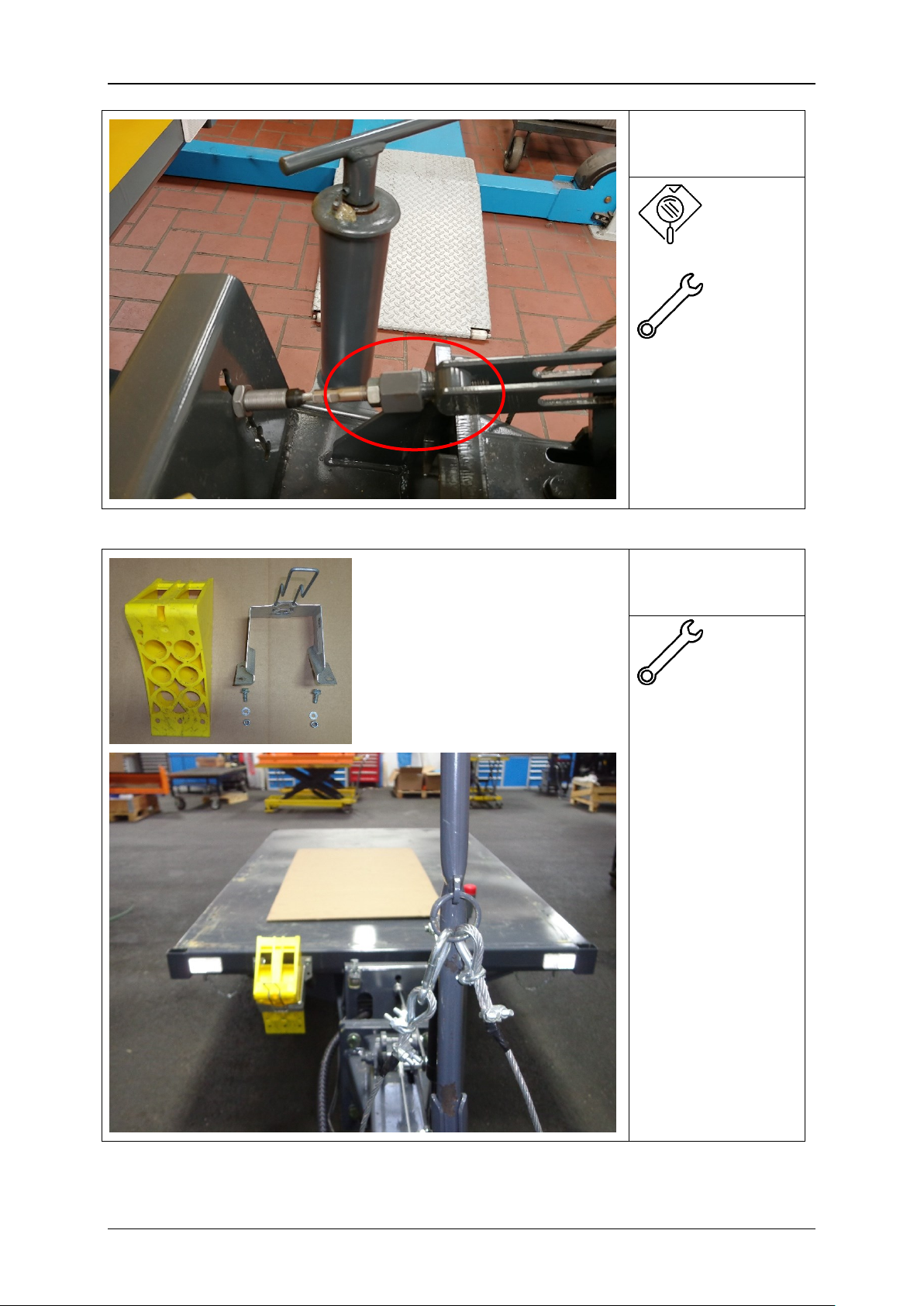
1. Disconnect the brake cable that connects the brake lever C with the hand brake lev-
er B at position A (Figure 1)
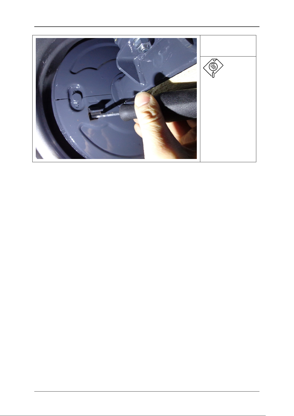
2. Push a screwdriver into the opening (Figure 2 - Ref. V). Here you will find the adjust-
ing screw. Turn the wheel by hand in the direction of the arrow while also turning
the adjusting screw, likewise in the direction of the arrow. Turn the adjusting
screw until the wheel is braked (hard to turn by hand).
3. Now turn the adjustment screw in the opposite direction until the wheel can turn
freely in the direction of the arrow.
4. After adjusting both brakes for the axle, check by hand whether both levers (Figure 1
- Ref. C) have the same stroke. If further adjustment is necessary, repeat step 2.
5. The maximum stroke of the cable / drawbar during operation should be about 75 mm
for a 150 mm brake lever. Adjust the levers so that they are perpendicular at half
stroke.
6. Check whether the telescoping drawbar (Figure 1) is fully extended and the lever
(Figure 1 - Ref. E) that pulls on the cable is fully retracted. Connect and adjust
the linkage under these conditions (Figure 1 - Ref. F) to prevent any backlash
7. Hitch the trailer to the tractor, pull the emergency brake lever and make sure that the
brake is effective both in forward and reverse and that the right and left brake ex-
ert an even braking force.
When pushing in reverse the tension of the hand brake lever will automatically
increase.
8. Release the hand brake lever again and check whether the reverse movement is
free.

1
Page 9
Figure 1: Schematic representation of the brake system
Figure 2: Adjusting the brake

Appendix A
Page 10
Functional characteristics of the braking system
Driving forward without brakes
The brake shoes B1 and B2 do not
contact the drum T. They are held
in position by the spring F1 and the
levers A and G. The wheel turns
freely. The telescoping drawbar is
fully extended.
Driving forward with brakes
The brake shoes B1 and B2 are
pressed by the cam N onto the
drum T. The friction between the
drum and the brake shoes increas-
es the braking effect. The braking
effect is ensured by the inertia of
the trailer, which presses on the
eye of the drawbar and mechani-
cally actuates the control cam N.

1
Page 11
Free reverse gear.
When driving in reverse, the friction
resistance between the brake drum
and the brake shoe B2 presses the
brake shoe B2 against the eccentric
A. The contact between the eccen-
tric and the brake shoe B2 is main-
tained by the spring on the eccen-
tric.
The slight friction between the
brake shoes and the brake drum
does not affect driving in reverse,
but is necessary to maintain the
function
Stability of the function is main-
tained by limiting the stroke of the
telescoping drawbar.
Emergency brake
Pulling the hand brake is the only
way to brake reverse movement.
The cam N can be turned further
with the hand brake lever, as with
the overrun mechanism of the tele-
scoping drawbar. This deflects the
eccentric A until its movement is
blocked by the stop, so that the au-
tomatic reverse function is disabled.
The hand brake lever is connected
to the tractor by a steel cable. If the
towing vehicle is separated from
the trailer, the steel cable actuates
the brake and functions as an
emergency brake.
Other manuals for TRL-3D 20
1
This manual suits for next models
1
Table of contents
Popular Utility Vehicle manuals by other brands

Neilsen
Neilsen CT2955 Instructions & assembly

Trailers
Trailers UtilityDump UD6096 Assembly guide

Husqvarna
Husqvarna HUV4420 owner's manual

URBANGLIDE
URBANGLIDE MONSTER user manual

Taylor-Dunn
Taylor-Dunn E0-455-24 Service and Replacement Parts Manual

Muck-Truck
Muck-Truck E Truck Owner & operator instruction manual