Matrix MPS-6003LP-3 User manual

USER MANUAL
Triple Output
Programmable DC Power Supply
Model MPS-6003LP-3 and MPS-
3006LP-3
© Copyright belongs to Matrix
1
USER MANUAL

CHAPTER 1 INSPECTION AND INSTALLATION....................................................................................................... 6
1.1 I
NSPECTION
................................................................................................................................................................ 6
1.2 DIMENSION................................................................................................................................................................. 7
CHAPTER 2 QUICK REFERENCE................................................................................................................................ 9
2.1 T
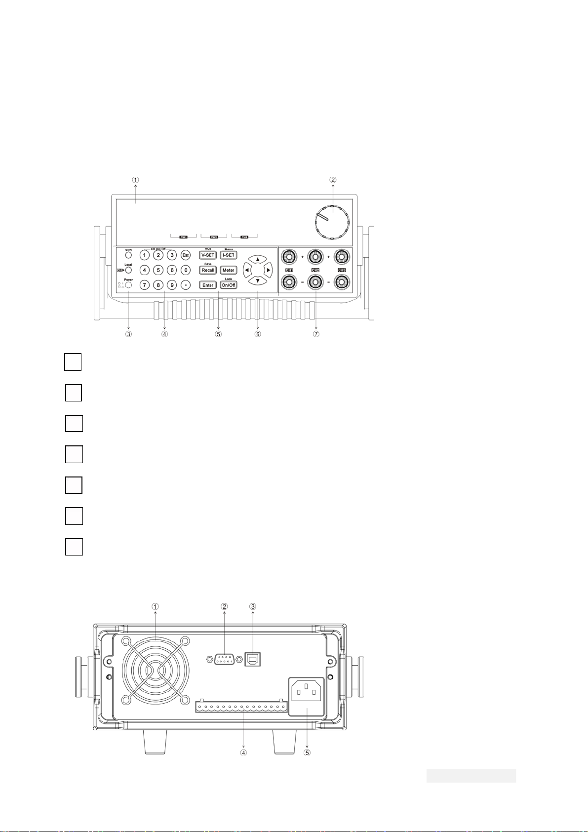
HE FRONT PANEL AND REAR PANEL DESCRIPTION
................................................................................................. 9
2.1.1 Front panel ...................................................................................................................................................... 9
2.1.2 The Rear Panel ............................................................................................................................................... 9
2.2 P
RELIMINARY CHECKOUT........................................................................................................................................ 10
2.2.1 Check the list of supplied items .............................................................................................................. 10
2.2.2 Power on Pre-check.................................................................................................................................... 10
2.2.3 Checkout procedure ................................................................................................................................... 11
2.2.5 If the power supply does not turn on ..................................................................................................... 13
2.2.6 How to exchange the fuse......................................................................................................................... 14
2.2.7 Adjust the carrying handle........................................................................................................................ 14
CHAPTER 3 SPECIFICATION ...................................................................................................................................... 15
3.1 S
PECIFICATION
......................................................................................................................................................... 15
2.2 A
DDITIONAL FEATURES
............................................................................................................................................ 17
CHAPTER 4 FRONT-PANEL OPERATION ................................................................................................................ 18
4.1 FRONT-PANEL OPERATION OVERVIEW.................................................................................................................... 18
4.2 P
ANEL DESCRIPTION ............................................................................................................................................... 19
4.3 VFD D
ESCRIPTION .................................................................................................................................................. 20
4.4 M
ENU DESCRIPTION ................................................................................................................................................ 20
4.5 P
ANEL OPERATION .................................................................................................................................................. 23
4.5.1 Channel Operation ...................................................................................................................................... 23
4.5.2 OUT ON/OFF ................................................................................................................................................. 24
4.5.3 Timer operation............................................................................................................................................ 24
4.5.4 Set Voltage .................................................................................................................................................... 24
4.5.5 Current Operation........................................................................................................................................ 25
4.5.6 Save and Recall Operation........................................................................................................................ 25
4.5.7 OVP operation .............................................................................................................................................. 25
4.5.8 Key Lock Set................................................................................................................................................. 26
4.5.9 Protections.................................................................................................................................................... 26
4.6 MENU DESCRIPTION ................................................................................................................................................ 26
CHAPTER 5 COMMUNICATION WITH PC ................................................................................................................ 32
5.1 RS232
INTERFACE
................................................................................................................................................... 32
5.2 USB
INTERFACE....................................................................................................................................................... 34
5.3 GPIB
INTERFACE ..................................................................................................................................................... 34
5.4 STANDARD SOFTWARE AND SCPI COMMAND.......................................................................................................... 34
USER MANUAL
2

About your safety
Please do not install replacement
parts in the instrument, or perform any unauthorized
modification. Please send the instrument to our company's maintenance department for
maintenance, to ensure its security features.
Please refer to the manual for specific information warning or precau
tions to avoid personal
injury or equipment damage.
There is no part that the operators can maintenance. If maintenance service is required,
please contact trained service personnel.
Security regulation
To prevent electric shock, a non
-authorized personnel is strictly not allowed to open the
machine.
This equipment is strictly prohibited for use in life support systems or any other device with
security requirements.
We can’t accept responsibility for any direct or indirect financial damage or loss of
profit that
might occur when using the electronic load.
Safety symbols
Warning
It reminds the user, note some operating procedures, practices, conditions and other
matters that may lead to human casualties.
Notes:
It reminds the user of some operating procedures, practices, conditions and other matters
that may result in instrument damage or data lose forever.
Connect it to safety earth ground using the wire recommended in the user manual.
The symbol on an instrument indicates that the user should refer to the operating
instructions located in the manual.
High voltage danger
Certification and Quality Assurance
programmable DC power supply fully meets all of the technical specification in the
manual.
Warranty
Our Company gives one year warranty for the materials and manufacturing of the product
since the date of shipment.
3
USER MANUAL

Warranty Service
For the warranty service or repair the product, the product must be returned to the
designated maintenance units. Return the product to us for warranty service, the customer
should pre
-pay the one-way Freight to the maintenance department, and our company is
responsible for the return shipping cost.
If products are returned from other countries for maintenance service, then the customer
should pay all freight, duties and other taxes.
Guarantee limit
The guarantee does not apply to the damage caused by the following conditions:
Improper or inadequate maintenance to the products by customer;
Customers use their own software or interface;
Unauthorized modification or misuse;
Operate this product not in the specified environment, or at the wrong place config
uration
and maintenance;
Damage from Customer self
-installation of circuit, or defects due to customers use their
products;
Product model or serial number of the fuselage has been altered, deleted, removed or
made illegible;
Damage caused by accident
s including but not limited to lightning, water, fire, abuse or
neglect.
Notice
If the content of this manual is subject to change, we will not notice additionally
USER MANUAL
4

MPS
-XXXXLP-3 DC programmable power supply
Introduction
MPS
-XXXXLP-3 triple output programmable DC power supply,the output voltage or current of each
channel can be set from 0 to max rated value.
The triple
output power supply provides you with high-resolution, high accuracy and high
stability, and supports over voltage, over temperature protection; Provides a serial or
parallel mode, used to extend the voltage or current output capacity. Resolution reache
s up
to 1mV/1mA that it can meet the needs of a variety of applications, and is a great choice for
University or R & D department and the manufacturer. The main features and advantages
are as follows:
Triple output voltage, all are adjustable.
CH1 and CH2 can set to serial/parallel/track mode.
The voltage and current for the three channels can be displayed at the same time
Small size of 1/2 2U
VFD display
Function keys with LED light
Remote measurement function, compensation online pressure drop
High accuracy 、resolution and stability
Switch to control the output status
Limited voltage and over heat protection
Intelligent fan control, energy conservation, noise reduction
Built-in RS232/USB/GPIB communication interface
Low ripple and low noise
Shut off memory function
Can be monitored by computer software
Can calibrate through software
Memory capacity of 36 groups, for save and recall
Can adjust the voltage or current by knob
Can adjust the stepping by Left/right arrow button
Output timer function (0.1 ~ 99999.9 seconds)
Model
Channel
CH1
CH2
CH3
CH1
CH2
CH3
Voltage
6
0V
6
0V
5V
Current
3A
MPS-
6003LP-3
3A
3A
30V
30V
5V
6A
MPS-
3006LP
-3
6A
3A
5
USER MANUAL

Chapter 1 Inspection and Installation
Power supply is a kind of high level safety
equipment with a protected ground terminal.
Before Installation or operation, please read the safety signs and instructions in this manual
1.1 Inspection
After receive the power supply, follow these steps to check:
1. Damage
When you receive your AC source, inspect it for any obvious damage that may have
occurred during shipment. If there is damage, notify the shipping carrier and the nearest
Matrix Sales and Support Office immediately.
2. Accessories
Make sure you receive the AC source and the following accessories at the same time, if any
is missing, please contact your nearest support office.
□
a power cord (a power cord appropriate for your location)
□a User’s manual.
□a factory calibration report
3. AC input
There are two kinds of mains input of MPS-XXXXLP-3(110Vac and 220Vac).
AC input level
110VAC ± 10%, 47 to 63 Hz
220VAC ± 10%, 47 to 63 Hz
Power cord type
E
E
E
E
L N
N
L
N
L
L
N
China
IT-E171
America,Canada
IT-E172
Europe
IT-E173
England
IT-E174
USER MANUAL
6

1.2 Dimension
1. MPS-XXXXLP-3 power supply’s dimension:
Dimension: 215mmW×90mmH×452.m12mmD (W:width H:height D:depth)
* refer to the Dimension below:
Front view for MPS-
6003LP
-3/MPS-3006LP-3
Lateral view for MPS-
6003LP-3/MPS-3006LP-3
7
USER MANUAL

Chapter 2 Quick Reference
2.1 The front panel and rear panel description
2.1.1 Front panel
1
VFD display
2
Rotary knob
3
Power switch, Local and Shift key
4
Numeric keys and ESC escape key
5
Function keys
6
Up/Down/Left/Right keys
7
Output terminal
2.1.2 The Rear Panel
9
USER MANUAL

1
Cooling window
2
RS232 communication interface
3
USB communication interface
4
Remote measurement terminal
5
110V/220V AC power selection
switch and Fuse
2.2 Preliminary Checkout
The following steps help you verify that the power supply is ready for use.
2.2.1 Check the list of supplied items
Verify that you have received the following items with your power supply, if anything is
missing, contact your authorized supplier.
1. Power cord
2. User manual
3. Calibration report
4. Certificate
2.2.2 Power on Pre-check
Before operation the power supply, please read the following safety guide:
Warning:The AC input voltage is 110V or 220V; please check the switching at the
bottom of the power supply, to make sure it matches the voltage in your
city. Otherwise, the power supply may be damaged.
Warning:The power supply provides a three-wire power cord; you should plug it
to a three cord junction box. You should also make sure the power supply is
well grounded.
Warning:The connection wire should have enough current capacity that it can
bear the max rated current/short current of the power supply and not get
USER MANUAL
10

too hot.
Warning:To avoid any fire or electric shock, please ensure the AC input voltage
fluctuation not exceed 10% of the working voltage range.
Note
:
In some situation, use the mis-configured main voltage for the instrument may
cause the main fuse blew.
Note:If the power supply is used to charge a battery, please pay attention to the
positive and negative polarity to avoid any damage.
After power up, the instrument will automatically perform a self test routine. If the power
supply doesn’t work, then refer to section 1.2.5.
2.2.3 Checkout procedure
After power on, during the self test, the following should be displayed on the VFD:
BIOS ver1.10
Init……
Scan System
Picture 3
About 1S later, if EEPROM was damaged, then the VFD will display (about 2S):
EEPROM Fail
Picture 4
If the latest operation state of the power supply was lost, then the VFD will display (about
2S):
System Lost
Picture 5
If send channel data, the channel response failure, the VFD display the tooltip information
(about 2 s)
Model Fail
11
USER MANUAL

Picture 6
If calibration data read failure, the VFD display the tooltip information (about 2 s):
Cal Lost
Picture 7
If the factory calibration data loss, restoring default data, the VFD display the tooltip
information (about 2 s):
Fact Lost
Picture 8
If the channel to send data loss, channel initialization failed, the VFD display the tooltip
information (about 2 s):
Model Lost
Picture 9
VFD display information as follows, the first row displays the voltage, the second row
displays the out
put state or the current . From left to right, as the first, second, third channel
voltage current display area.
0.000V 0.000V 0.000V
0.000A 0.000A 0.000A
Picture 10
Note: the figure 10 is configuration menu (Config) for the factory set up on display,
the different OutState and OutParam setting in the menu will affect on the final state
of the display.
2.2.4 Output verification
The following procedure verify that the power supply outputs the correct voltage and current
levels and properly
responds to entries from the front panel.
Voltage Output Check
The following steps verify basic voltage function without load.
1) Press Power key to turn on the power supply
2) Press On/Off key to enable the output
3) Set the voltage value
Adjust the voltage, then press
to lit the key (indicates it is in the METER mode),
make sure that the set value and output value are same, and if the current displayed on
the VFD is nearly 0A.
4
)Make sure the voltage can be adjusted from zero to the maximum rated value.
5
)
Check the other two channels by the same method.
USER MANUAL
12

Note: when
Meter key is gray, the power supply is in SET mode, then the VFD
displays the set voltage and current; when the key is lit, then the power supply is
in METER mode, the actual voltage and current display on the VFD. When the
output is OFF, the “OFF” indicater will display at the current display area.
Current output Check
The following steps check the basic current functionality by shorting the power supply’s
output.
1) Press Power key to turn on the power supply
2) Press On/Off
to disable the output, ensure the output is OFF.
3) Connect a short across (+) and (-) output terminals with an insulated test lead, use a
wire sufficient to handle the maximum current.
4) Adjust the voltage value to 1V
5) Press
On/Off to enable the output
6) Adjust t
he current
Set some different current values, in METER mode, check whether the voltage value on
VFD is near 0v, and the current on it is close to the value you set.
7) Make sure that the current can be adjusted from 0 to full rated value.
8) Disable the output and then remove the short wire
9) Check the other two channels by the same method.
2.2.5 If the power supply does not turn on
Use the following steps to help resolve the problems you might encounter when turn
on the instrument:
1) Verify that there is AC power applied to the power supply
First, verify that the power cord is firmly plugged into the power receptacle on the rear
panel of the power supply. You should also make sure that the power source you
plugged the power supply into is energized. Then, verify that the power supply is turned
on.
2) Verify the power-line voltage setting
Make sure the voltage selector switch is set according to the present line voltage
(110VAC or 220VAC) when the power supply is shipped from the factory. Change the
voltage setting if it’s not correct.
3) Verify the correct power
-line fuse is installed
If the fuse was damaged, please see the table below to replace the fuse for your power
supply.
Model
Fuse (220V AC)
5A T250V
5A T250V
Fuse (110V AC)
10
A T250V
10A T250V
13
USER MANUAL
MPS-6003LP-3
MPS-3006LP-3

2.2.6 How to exchange the fuse
Open the small plastic cover below the power supply input socket on the back panel with a
screwdriver, and you can see the fuse in it, please use the specifications in line fuse.
Remove the power cord and then use a screwdriver to remove the fuse box.
Use the same specification of fuse to replace the old one, install it to the fuse box and then
insert.
2.2.7 Adjust the carrying handle
To adjust the position, grasp the handle by the sides and pull outward. Then rotate the
handle to the desired position.
Bench operation
Handle
USER MANUAL
14

Chapter 3 Specification
3.1 Specification
Parameters
Rated voltage
Voltage
Current
Voltage
Current
Voltage
Curr
ent
Voltage
Current
Voltage
Current
0~30V×2,0~5V×1
( 0 °C - 40 °C)
0~6A×2
,
0~3A×1
≤
0.01%+3mV
≤
0.1%+3mA
≤
0.01%+3mV
≤
0.1%+3mA
1mV
Load regulation
(
%
of output+offset)
Line regulation
(%of output+offset)
Setting resolution
1mA
1mV
Readback resolution
1mA
Setting accuracy
(
Within 12 months)
(25 °C ± 5 °C)
≤0.03%+10mV
Voltage
Current
(
%
of output+offset)
≤0.1%+8mA
Readback accuracy
(25 °C ± 5 °C)
Voltage
≤0.03%+10mV
(%of output+offset)
Current
Normal mode
voltage
≤0.1%+8mA
≤
4
mVp-p/≤1mVrms
Ripple and noise
(20Hz-20MHz)
Normal mode
current
≤5mArms
TEMP coefficient
(0 °C ~ 40 °C)
Voltage
≤0.03%+10mV
(
%
of output+offset)
Readback Temp.
coefficient
Current
Voltage
≤0.1%+5mA
≤0.03%+10mV
Current
≤0.1%+5mA
(%of output+offset)
Series synchronous
operation
Series
≤0.05%+10mA
synchronous error
Voltage
≤0.02%+5mV
≤
0.1%+30mA
40 groups
Parallel accuracy
Memory
Current
Save/recall
Time set
0.1~99999.9second
Timer
Resolution
Function
0.1second
Output timer
15
USER MANUAL
MPS-3006LP-3

Parameters
Rated voltage
Voltage
Current
Voltage
Current
Voltage
Current
Voltage
Current
Voltage
Current
0~60V×2,0~5V×1
0~
3A×2,0~3A×1
≤
0.01%+3mV
≤
0.01%+3mA
≤
0.01%+3mV
≤
0.01%+3mA
1mV
( 0 °C - 40 °C)
Load regulation
(
%
of output+offset)
Line regulation
(%of output+offset)
Setting resolution
1mA
1mV
Readback resolution
1mA
Setting accuracy
(
Within 12 months)
(25 °C ± 5 °C)
≤0.03%+10mV
Voltage
Current
Voltage
(%of output+offset)
≤
0.03%+10mV
≤0.1%+5MA
Readback accuracy
(25 °C ± 5 °C)
(%of output+offset)
Current
Normal mode
voltage
≤0.1%+8mA(6A)
≤
4mVp-p(60V)
≤0.1%+5Ma(3A)
≤3mVp-p(5V)
Ripple and noise
(20Hz-20MHz)
Normal mode
current
≤4mArms(3A)
≤4mArms(3A)
TEMP coefficient
(0 °C ~ 40 °C)
Voltage
≤0.03%+10mV
(
%
of output+offset)
Readback Temp.
coefficient
Current
Voltage
≤0.1%+5mA
≤0.03%+10mV
Current
≤0.1%+5mA
(%of output+offset)
Voltage
≤0.02%+10mV
≤
0.1%+30mA
40 groups
Parallel accuracy
Memory
Current
Save/recall
Time set
0.1~99999.9second
Timer
Resolution
Function
0.1second
Output timer
USER MANUAL
16
MPS-6003LP-3
≤0.1%+5mA
≤0.1%+5mA
Working temperature 0-40°C
Dimension 214.5mm X 88.2mm X 453.1mm (W x H x D)
Weight 15kgs

Chapter 4 Front-panel Operation
So far we have covered the quick start chapter which briefly introduced the front panel
operation and how to check basic voltage and current functionalit
y. This chapter describes
in detail how to operate the instrument manually via the front-panel keys.
4.1 Front-panel Operation Overview
The power supply is shipped from the factory ready for front-panel operation mode. At
power-on, the power supply will automatically enter the front-panel operation mode and
the instrument can be controlled via the front panel keys and knob.
The VFD also displays operation states or error information. “
”means the power
button will be lit.
supply is in remote mode.When front-panel keys are locked,
“
” means the power supply keyboard locked .For more details, please refer to
chapter of “Descriptions about VFD marks”
If the power supply is in set mode, you can modify parameters using the knob. If the
power supply is in menu operation, the knob is used for menu selection.
V-set
I-set
Recall
On/Off buttons are lit,means they are
When
,
,
,
or
selected and under corresponding state now.If pressing
(Shift)+
Recall (Save),
Recall button will keeping lighting and waiting for a number to be entered to specify
the memory location.
USER MANUAL
18
The power supply is in Set mode when it is powered on. In this mode, the VFD will
display the setting voltage and current.
The output of power supply can be enabled/disabled from the front panel by
pressing the On/Off button.When turn on the output,the VFD will display the state
and voltage/current of each channel.”CC” represents constant current mode.”CV”
represents constant voltage mode.
When output is in OFF mode,VFD will have
no any indicators of CC or CV.

Details about key buttons’ state
:
V-set
When button is lit, means you can set voltage.
When button is lit, means in current setting mode.
When button is lit, means in recall mode
I-set
Recall
When button keeps flickering, means in save mode and waiting for a number
to be entered to specify the memory location.
When button is lit, means current VFD displays actual voltage and current.
When button is lit, means at least one channel output is on. Or all channels
are in OFF mode.
On/Off
V-set
I-set
, Recall buttons will not be lit at the same time.
Note:
,
4.2 Panel Description
0~9
Numeric keys.Use keys 1~3 to control the output state of the 3
channels which should coordinate with Shift key.Note:In key
lock mode, Shift key is not needed.
Escape from the current setting or menu item.
Compound key
(Shift)
Used to switch to local operation mode
(Local)
19
USER MANUAL

(Power)
Used to power on/off the DC source
Used to set the voltage or shift+V-set to set OVP value
V-set
/OVP
I-set
/Menu
Used to set the current or shift+I-set to enter the menu
operation.
Recall /Save
Save or recall different operating parameters in memory
locations
Switch the display between setting value and actual value
Enter button to confirm the selection or Shift+Enter to lock the
front keys
Enter
/Lock
On/Off
Used to control the output state of all channels
Right/Left key,use to move the cursor or scroll through the
menu items
Up/down key,used to increase or decrease the setting value
Used to turn on the output of corresponding channel no matter
in menu operation or Meter state
(Shift)+1,
(Shift)+2,
(Shift)+3
4.3 VFD Description
Explanation of enunciators on the display
C
In constant current mode
V
In constant voltage mode
Keyboard operation for
the lock mode
open the remote sense
function
Indicates the shift button is
pressed
↑
Indicates the channel
currently selected
Enable tracking mode
T
4.4 Menu Description
Press
(Shift)+
(Menu) to indicate operation mode.View the menu on the
USER MANUAL
20

VFD,and use the right/left key to change the setup, and up/down key to scroll through the
Esc button
Enter
complete menu items. Press
to enter the selected menu function.Press
to return to the previous menu.When the item keeps filickering indicates it is selected
currently.
Power Menu...
System
System Menu
System Menu…
System Menu
OutState
Power Out
Power supply power on
output state Settings
State Set
O
ff
all along OFF
Keep the last time state
before the shutdown
Set up the related
parameters when power
on
Keep
OutParam
Power Out
Param Set
Reset
default
Restore the last time
parameters
Keep
Knob
Knob Function
Set
Pulsating knob function
Settings
Pulsating knob function
open
Unlock
Lock
Pulsating knob function
closed
Buzzer
Power Key
Beeper Set
Off
Key sound
establishment
Key sound closed
Key sound open
Communication
interface choice
RS232
On
Communication
Communication
Select
USB
21
USER MANUAL
Choose RS232 communication
interface
Choose USB communication
interface

4800
9600
19200
38400
57600
115200
GPIB
Choose GPIB
communication
interface
Communication
Address
GPIB communications address
Address=15 (0~31)
Choose USB
communication
interface
USB
ExtPort
ExtPort
settings…
None
External interface
Settings
MemoryGroup
Select Memory
Group
Memory group set
GRP1
Group 1
Group 2
Gro
up 3
Group 4
GRP2
GRP3
GRP4
Command
SCPI Version
Select…
MATRIX
SCPI version select
ITECH SCPI command
Extended SCPI
command 1
EXT1
Return Meter
Auto Return to
Meter State
Off
The front panel display will change from setting to meter state
Wait5Sec
automatically after 5s.
Reset
Reset Menu
Default
Reset to
No
Yes
System
Channel Sel …
CH1
System Menu…
USER MANUAL
22
BaudRate
Choose BaudRate
Auto return to meter state
Function off
Exit
This manual suits for next models
1
Table of contents
Other Matrix Power Supply manuals
Popular Power Supply manuals by other brands

Wealtec
Wealtec ELITE 600 Installation and operation manual

Daintree
Daintree GE Tetra GEPS24-200U-GLX2 installation guide

Puls
Puls CP5.241 Instructions for installation manual

VersaLogic
VersaLogic EPM-PS1 Reference manual

Whelen Engineering Company
Whelen Engineering Company WPPS6924 installation guide

Pulsar
Pulsar GREEN POWER CCTV POE042455B manual