Matsushima MWLM-FM79 User manual

TMMFM-001E
Rev.1:Nov 25, 2022
Safety precautions1
Overview
Specifications 3
System configuration 6
Dimensions 7
Installation 9
Wiring 13
Display 14
Troubleshooting 16
. Maintenance 16
1-8-18 Norimatsu-Higashi,Yahatanishi-ku,Kitakyushu 807-0837 Japan
Phone No.(8193)691-3731 Fax No.(8193)691-3735
https://www.matsushima-m-tech.com
E-mail : sales@matsushima-m-tech.com
Instruction manual for
Radar level transmitter
Type:MWLM-FM79
Contents
※The operator should read this Instruction Manual carefully
and handle the device correctly.

1
⚫Be sure to thoroughly read the instruction manual before using the products.
⚫Keep the instruction manual in a safe, convenient location for future reference.
⚫All or part of the contents described in this manual may be changed without any notice.
⚫Due to our constant striving for further improvement of products, parts or products
that differ from those described in this manual may be substituted.
Safety precautions
WARNING
(Failure to observe this WARNING may cause a fatal or serious injury.)
-Be sure to confirm that any peripheral equipment does not move before installation work.
In addition, observe safety requirements for installation work where high-place work is expected.
-Be sure to turn off the power source before wiring, mounting and transportation work.
(Failure to observe this WARNING may result in an electric shock/ injury or equipment damage due to
short-circuit.)
-Carry out wiring work correctly with reference to a proper drawing.
-Never disassemble the equipment.
(Failure to observe this WARNING may result in an electric shock.)
-Do not open the cover under an explosive environmental condition when power is supplied.
(Failure to observe this WARNING may result in an injury or equipment damage.)
-Do not place or store the equipment in any hostile environmental place where it will be
subjected to direct sunlight, rain, water droplet, hazardous gas / water, etc...
IMPORTANT (indicates notes or information to help customers.)
Limitations of Warranty:
-Warranty period shall be one year from the date of shipment (ex-factory).
-Any damage of any other products that have occurred for use of the equipment is not covered by this
warranty. Also, any loss induced by failure or malfunction of the equipment is not covered by this
warranty.
-Failure or malfunction caused by following are not covered by this warranty:
r replacement of
parts not accepted by Matsushima.
b. Inadequate storage, installation, use, inspection, or maintenance that does not comply with
specifications.
c. Cause for any peripheral equipment or device.
d. Accident beyond control and force majeure (fire, earthquake, flood, riots, etc.).
-Lack of instructions to Matsushima for information or safety requirements that can be predicted only
by
-
-Price for the equipment does not include any charge for services such as commissioning,
supervising, etc...
CAUTION
(Failure to observe this CAUTION may cause a moderate injury or equipment
damage.)
-Do not use the equipment for any purpose other than the original purpose of use.
-Be sure to confirm the specification of equipment and use the equipment within the range of
specification. (Mounting conditions such as temperature, power source, frequency, etc.)
-Make sure a correct wiring before applying power source.
-Do not have a shock or strong impact to the equipment.
(Failure to observe this CAUTION may result in equipment damage.)
-Be sure to connect necessary terminals (grounding, etc.).
-Remove all wiring to the equipment before doing electrical welding work near the equipment.
-Do not forcedly bend or pull the lead wire also do not use unnecessarily long wire.
-Tighten the cover, lead outlet, etc. properly so that dust, rainwater, etc. do not enter
inside the equipment.
-Do not use the equipment
under a corrosive condition (NH3, SO2, CI2, etc.).

2
・Bluetooth wireless communication
・Bluetooth とは
Bluetooth is wireless communication technology between digital devices in relatively short
distance by connection with a PC or a smartphone. No need to connect with devices by an USB
cable, and wireless communication with data can be available at anywhere in short distance
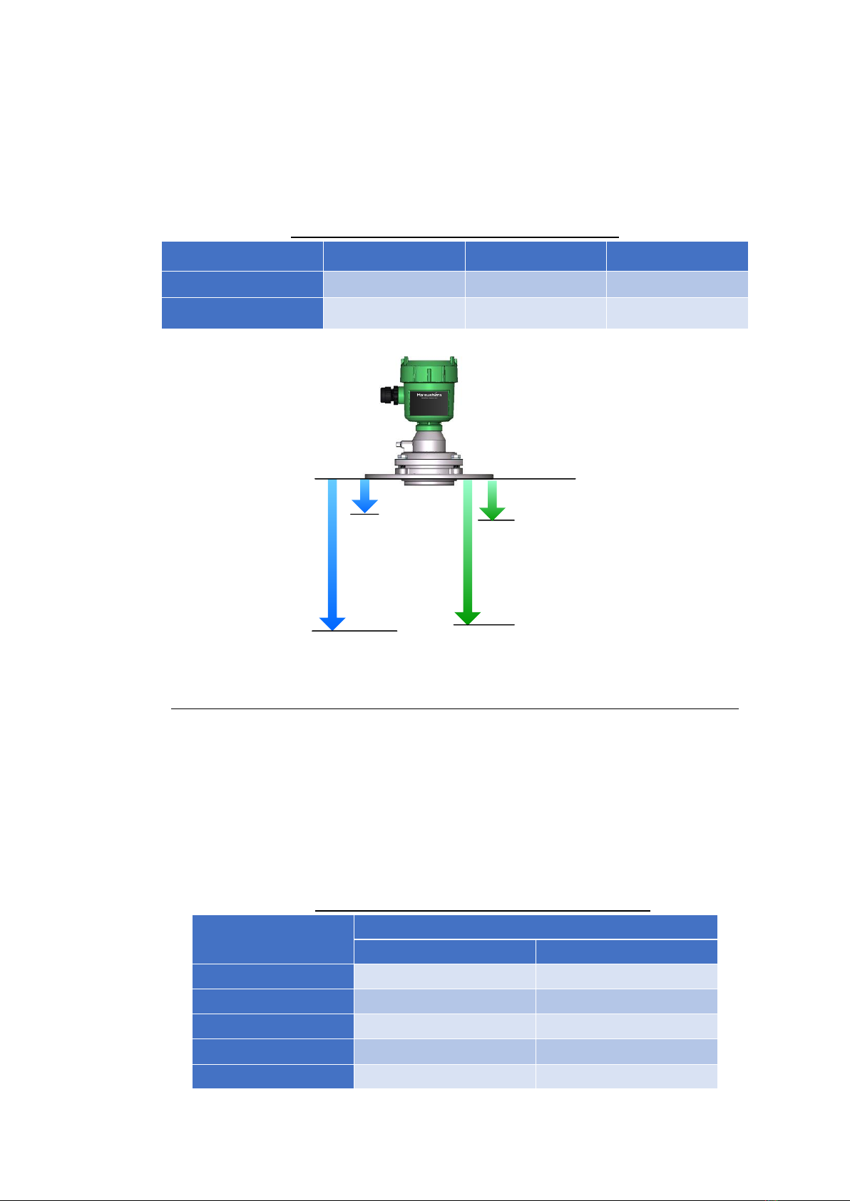
(within approx. 10m viewable area).
・通信可能範囲にて
Distance for Bluetooth communication is within approx. 10m viewable area. Available
connection distance will be changed by any block of walls and metals, or around situation and
building shape. Make sure of using no barrier place, as much as possible.
・セキュリティについて
Make sure that we do not have any responsibility for any case of data leaking. We recommend
setting the password due to higher security.
Refer to the Instruction manual for an app of Reader level transmitterfor setting the
password. If the password is set up, Reader level transmitter will be locked and parameters
including other specifications will not be available to be changed. We recommend that the
password must be updated routinely for higher security.
・本機の機器認定について
No need a license of radio station to use because this product has been approved upon Radio
Act as the wireless system for power saving data communication. However, breaking, remodeling,
and removing nameplate may be punished. This approval can be applied only in Japan.
・使用周波数と注意事項
Usable frequency of Bluetooth (range 2.4GHz) will be used for in-house radio stations (license
required), specified low power radio stations (no license required) for mobile facilities in factory
at fields of household appliances, industry, science, medical devices and mobile detectors in
factory, and amateur radio stations (license required).
1. Make sure of confirming no in-house radio station for mobile detector, specified low power
radio station and any amateur radio station near before starting to use.
2. Keep a distance from any electric device as much as possible. If any harmful radio wave
interference occurred, immediately cut the power supply to the device.
3. In case of strong radio wave from any radio station or wireless device, it may not be able to
connect normally.
4. Please be sure that connection with Bluetooth will cause the battery of the connected device
drains faster.
・Trademark/Software license
-The logo Matsushima Measure Tech Co., Ltd.is our brand and registered trademark.
-Copyright of FM79 Smart Com.is reserved by Matsushima Measure Tech Co., Ltd..
-The Bluetooth and its logo are the registered trademark of Bluetooth SIG, Inc..
What is Bluetooth?
Available range for communication
Security
Product approvals
Usable frequency and handling instructions

3
1. Overview
Radar level transmitter measures the level of powder and liquid material by the
non-contact method, and it makes stable measurement by applying
electromagnetic wave (radar).
This transmitter outputs the analog signal (DC4mA to DC20mA) directly on the
transmitter power line.
This device transmits a higher frequency signal from the antenna corresponding
to time passage. It measures with a suitable frequency which is given by phase
detection using received signal reflected from the storage surface and
transmission signal.
2. Specifications
Table 1. Specifications
Item
Specification
Type
MWLM-FM79
Version
S03
F03
S06
F06
S12
F12
Antenna
Lens
Power supply (#1)
DC12V to DC36 V
Power consumption
800 mW
Mounting
Equivalent JIS10K100A flange
with Swiveling mechanism
Equivalent JIS10K80A
fixed flange
Measurable
distance(#2)
Min.
0.3 m
0.4 m
0.7 m
Max.
30 m
60 m
120 m
Transmitting frequency
77 GHz to 81 GHz
Beam angle(-3dB)
Approx. 4including side beam approx. 8
Resolution
1 mm
Accuracy (#2)
3 mm
5 mm
10 mm
Analog error
10 A
Measurement cycle
(#3)
Approx. 0.4 s to 4 s (for DC24V)
Temperature error
6.4 A/10, Max.48 A
Ambient temp.(#4)(#5)
-20 to +80
Process temp.(#6)
-40 to +200
Allowable pressure(#7)
490 kPa
Material
Housing
PBT
Flange
Equivalent to SUS316
Antenna
PEEK
Protection(#8)
IP67
(Housing cover and lead outlet must be closed.)
Air purge pressure (#9)
Flow approx. 200L/minfor 0.1a
Lead outlet
1-G1/2(Applicable size8mm to 12mm)
Output signal
DC4 mA to DC20 mA
Integral time
0 to 999 s
Mass
4.0kg
4.3kg
4.0kg
4.3kg
4.0kg
4.3kg
Bluetooth
5.0

4
(#1) No interfusion of noise surge with less 10% of ripple on power supply voltage for
instrumentation.
Maximum
load resistance depends on power supply voltage. Please refer Fig.1.
Make sure that wiring load will not over maximum load resistance value on applied
power supply voltage.
(#2) The range and accuracy of measurement must be over 2 of dielectric constant on the
measuring medium facing even to antenna surface at normal temperature (232)
and without floating dust, steam, bubbling, form, barriers.
The range and accuracy of measurement will be changed out of the above conditions.
In case of less than 1.1m, the accuracy is
10mm(Ver. S03/F03) and 20mm(Ver.
S06/F06/S12/F12).
(#3) The measurement cycle depends on power supply voltage and output current value.
Please refer to Fig. 3.
(#4) Make sure of no freeze and condensation in the housing inside.
(#5) If ambient temperature is over +70, the display will be OFF.
(#6) In +80or higher process temperature, applicable ambient temperature is changed.
Please refer to Fig. 2.
(#7) This is a pressure of balanced case of the ball of the flexible flange. If not balanced,
its sustaining power will be weakened.
(#8) If the lead outlet has some loosing cap and gap, the damage may occur with water
intrusion. In case of using gas or steam, electronic devices may damage. Please be
careful to use in above.
(#9) Recommendable purge pressure is tank pressure +0. MPaif 0.1MPa, approx.
200L/min.
Please adjust the purge pressure if it is not effective with the recommendable
purge pressure.
Fig. 1. Power supply voltage vs. Maximum load resistance
Power supply voltage [V]
Maximum load resistance value []

5
Fig. 2. Process temperature vs. Ambient temperature
Fig. 3. Output current value vs. Measurement cycle
(Typical value)
Process temperature []
Ambient temperature []
Output current value [mA]
Measurement cycle [s]

6
3-1. System configuration
This product is the 2-wire system with DC4mA to DC20mA signal on the DC
power supply line.
-Supply voltageDC12V to 36V
-Output current signalDC4mA to DC20mA
-Load resistanceMax.545for DC24V
-Cable size0.3mm2to 1.25mm2(AWG22 to AWG16)
-The earth terminal (D-class grounding) is no connection with the antenna.
-Use over 1.25mm2 grounding wire.
Fig. 4System configuration example
Important
: For protection and safety of human body and the total system incl. Level
Radar
transmitter, comply with the safety instruction of this Instruction Manual at operation.
If it is not operated in compliance with these instructions, we will not guarantee
the safeness.
Further this Radar level transmitter has the structure and includes the components
satisfying the safety requirement of electrical equipment and accordingly the
modification without consultation is strictly prohibited.
: The products are designed for discrete wiring connected to current loop supply or
isolated interface device and analog board.
If there is anything unclear about the other connection, please consult with us
separately.
-2. Adjustment device
Use adjustment device after installing the adjustment app FM79 Smart Com.
on a PC, a tablet, and a mobile phone with Bluetooth.
Please refer the following data for installation and handling adjustment app;
-Instruction manual of app for Radar level transmitter
3. System configuration
AC100V
DC24V
D
2
DC24V Bluetooth
DC4mADC20mA
Adjustment device
Radar level transmitter
AC power supply
Ammeter
D-class
grounding
Two-core
shielded wire
DC24V
Loop power supply

7
4-1. Swiveling flange : Version S03/S06/S12
(122)(79)(10)
8(129)
(49)
(92)
(81)(97)
Max.10
210
JIS10K100A
P.D.175
8-19
62
G1/2
8-12mm
Rc1/8
PC
/
PBT
4-M8
PEEK
M4
Max.10
Fig. 5-1Swiveling flange dimensions
4. Dimensions
Measurement
reference
point
Display
Transparent window : PC
4-M8
Fixing bolt for angle adjustment
Lead outlet G1/2
Cable size 8-12mm
Cover/
Housing : PET
Antenna
Lens antenna
PEEK
8-19 Mtg. holes
JIS10K100A
Equivalent to SUS316
M4 Earth
terminal
Rc1/8
Purging hole

8
4-2. Fixed flange : Version F03/F06/F12
(202)(8)
(129)
(49)
(81)(97)
185
JIS10K80A
P.D.150
8-19
62
G1/2
8-12mm
Rc1/8
PC
/
PBT
PEEK
M4
Fig. 5-2Fixed flange Dimensions
Display
Transparent window: PC
Lead outlet G1/2
Cable size 8-12mm
Antenna
Cover/
Housing : PET
Lens antenna
PEEK
8-19 Mtg. holes
Measurement
reference
point
JIS10K80A
Flange: Stainless steel
M4 Earth
terminal
Rc1/8
Purging hole
JIS10K80A
Equivalent to SUS316

9
5-1. Min./Max. measurable distance
In case of shorter measure distance than min. measurable distance (inside of
dead zone), use an additional short pipe to keep the measured material out of
dead zone.
Table 2Min./Max. measurable distance
Fig. 6Min./Max. measurable distance and Min./Max. measuring level
5-2. Size of short pipe
Use an additional short pipe if the measured material goes up to the dead zone.
Do not use an unnecessary length of short pipe to prevent unstable
measurement.
# Install a short pipe not to leak electromagnetic wave from a gap for
preventing noise.
Table 3Recommendable short pipe size
Inner dia.
Max. length
Vertical mounting
Mounting angle 10
80mm
150mm
-
100mm
250mm
50mm
150mm
600mm
150mm
200mm
950mm
250mm
250mm
1300mm
350mm
5. Installation
Version
S03/F03
S06/F06
S12/F12
Minimum
0.3 m
0.4 m
0.7 m
Maximum
30 m
60 m
120 m
100(20mA)
0(4mA)
Measurement
reference point
Min. measurable
distance
Max. measurable
distance
Min. level distance
Max. level distance
Blind range

10
-3. Range of radiation angle
Set instrument out of any obstruction with noise and keep clear in range of
beam angle (including side beam).
Calculation of radiation angle extent
Beam angle range Distance from measuring point tan+
Antenna surface62mm
Main beam4, Side beam8
tanMain beam0.07, Side beam0.14
Example
When 3000mm 4main beam
3000tan+62
30000.07+62
272 mm
When 3000mm 8side beam
3000tan+62
30000.14+62
482 mm
Fig. 7Beam angle range
Table 4Measuring distance and beam angle range
-4. Installation precautions
-If any beam or H-beam in the tank, please make a smaller risk of obstructive
reflection with using a shield plate.
Fig. 8. Installation precaution (1)
Measurement
distance
10 m
30 m
60 m
120 m
Extent of main beam
0.7 m
2.2 m
4.2 m
8.4 m
Extent of side beam
1.4 m
4.2 m
8.4 m
16.8 m
4
8
H
X
Measurement
reference point
Main beam4
Side beam8

11
-Do not install instrument close to inlet of material charging.
Fig. 9. Installation precaution (2)
-No obstruction with noise in range of radar beam.
Fig. 10. Installation precaution (3)
- For liquid application, keep vertical position to material surface.
Fig. 11. Installation precaution (4)

12
(Noise reflection)
Noise reflections can cause inaccurate or unstable level measurement.
Noise reflection can be treated by adjustment app. In case of receiving no
reflection or quite small dB from the material surface, the installed position must be
changed.
If there is any such obstruction in the tank, please install the transmitter where
there is no obstruction within the range of beam angle.
Important:
It is not possible to specify the range of false reflections in dB that can be suppressed
by the learning function because the level of actual reflection from the surface of
material depends on the Radar level transmitter installation conditions and measuring
material type. The general guideline for the level of false reflections that can be
suppressed by the learning function is one third (1/3) of actual reflection level.
-Install protection such as a simple roof above the Level Meter to avoid exposure
to direct sunlight.
Use a well-ventilated cover as simple roof.
Fig. 12. Installation precaution (5)
Simple roof

13
6-1. Remove the cover. (Turn counterclockwise)
6-2. Terminal inlet will open after inserting a flathead screwdriver into the terminal
block lever.
Insert a lead wire in opened terminal inlet. (Recommendable flathead
screwdriver: Dia. 3mm, Width 3mm)
Connect +with DC power supply (DC24V) positive terminal and -with
negative terminal.
6-3. In case of no grounding of two-core shield wire in power supply side, connect
two-core shield wire with terminal in the transmitter case and fix D-class
grounding of M4 earth terminal.
6-4. Set the cover. (Turn clockwise)
The size of a grounding wire must be used larger than 1.25 mm2
Fig. 13. Connection example
Important:
The size of the acceptable cable is 0.3mm
2
to 1.25 mm
2
. (AWG22 to 16)
Warning:
Do wiring when the instrument is powered OFF.
Avoid short circuit and reverse polarity.
The instrument must be supplied with DC power supply do not apply different voltage.
Tighten the cover and lead outlet firmly after wiring completed.
: The products are designed for discrete wiring connected to current loop supply or
isolated interface device and analog board.
If there is anything unclear about the other connection, please consult with us
separately.
Power Supply
AC100V
2
DC4mADC20mA
DC24V
4M
(D)
6. Wiring
Radar level transmitter
AC power supply
Ammeter
D-class
grounding
Two-core
shielded wire
DC24V
Loop power supply

14
7-1. Screen of measurement
FM79―001
12.345
Distance
m
LockBLE
Bluetooth
BLE
Fig. 14Display screen
Table 5Details
Item
Content
1.Bluetooth device name
Display Bluetooth device name
(available to change by adjustment app)
2. BLE mark
Display Bluetooth connection with transmitter and
adjustment device
Display: ON, Non-display: OFF
3. Device protection
Display protection of devices
Display: Protecting (Lock), Non-display: Releasing (Unlock)
4. Measurement value
Display measurement value (available to change by
adjustment app)
DistanceLevel distanceLevel PercentCurrent value
5. Indication value
Display indication of 4. Measurement value
DistanceLevel distanceLevel PercentCurrent value
7-2. Display of conditions
Table 6Conditions
Display
Content
Communicating
Parameters changing
Monitoring
Monitoring waveform on radar app monitoring
Processing
Noise echo leaning processing on transmitter
Device failure
Failure on device of transmitter
Device busy
Device busy of transmitter
No response
No response from transmitter
7. Display
1. Bluetooth device name
3. Device protection
4. Measurement value
5. Indication value
2. BLE mark

15
7-3. Display of error, warning, notice
Try actions in Table 7 if any code is displayed on screen.
Table 7Code and action
Code
Condition
Comment
Current
output
F001
Memory error
Description: The memory part malfunctions.
Action: Reset power supply.
Depending on
output setting,
if trouble
<3.6mA to
22mA>
F002
RF module error
Description: The RF module part malfunctions.
Action: Reset power supply.
F003
Power charge error
Description: The charge circuit malfunctions, or the
supply voltage is out of range.
Action: Check supply voltage range: 12V-36V.
Reset power supply.
F004
Loop current error
Description: The current output value is out of
allowable range.
Action: Check the load resistance value.
Check the supply voltage range (12V to 36V).
F005
Lost echo error
Description: No reflection within measuring range
span.
Action: Check the surface of the antenna for any
adhesive materials, and clean inside antenna.
Check the measurement range.
S009
Startup processing
Description: State during startup processing of
device.
Action: Wait for detecting reflection.
<3.6mA
S010
Temp. out of range
Description: The temperature inside the device is out
of range.
Action: Check the ambient temperature.
Keep output
value of
measurement
S011
Full alert
Contents: It goes beyond the upper limit, full
amount (100%).
Action: Check the actual material level.
Check the measurement range.
S012
Empty alert
Contents: It goes below the lower limit, empty
amount (0%).
Action: Check the actual material level.
Check the measurement range.
S013
Measured value alert
Description: The measured value is out of range.
Action: Check the parameter range.
M017
LCD comm. error
Description: The LCD communication in the device is
abnormal.
Action: Reset power supply.
If occurring
Maintenance
notice =
Select current
output
If available,
maintenance
notification
setting
current output
M018
Internal comm. error
Description: The time communication in the device is
abnormal.
Action: Reset power supply.
M021
Antenna cleaning
Description: The antenna is dirty.
Action: Clean the antenna.
M022
Maintenance date
Contents: The set maintenance date has been
passed.
Action: Perform maintenance and update the
maintenance date.
C041
Simulation
processing
Condition: Performing simulation
Simulation
value
If the problem is not solved, please contact your local Matsushima sales office.

16
8. Troubleshooting
If you face any problems, first check if the following description to solve the
problem.
Table 8Troubleshooting
If problem persists, please contact your local Matsushima sales office.
9. Maintenance
Routine maintenance will be recommended.
Table 9. Periodic inspection
No.
Item
Descriptions
Interval (standard)
1
Check of appearance
-Confirm whether there is damage on housing
etc...
-Tighten the cover and lead outlet
-Tighten the bolt for installation fixture
Every 12 months
2
Check of antenna
-Clean the antenna
Every 6 to 12 months
Important:
Standard periodic inspection interval depends on measurement
condition and measured material.
No.
Problem
Check the following
Corrective actions
Powered ON the device,
but screen is blank
-Are wiring connections correct?
-Check whether the power is
supplied to the device?
-Check power supply DC12V to 36V
-Check whether load resistance is
within allowable range?
-Correct the wiring
-Supply proper power to the
device
-Reduce load resistance
Measured level reading
higher than material
level
-Are there any obstructions between
sensor and material surface to be
measured?
-Any adhesion on antenna surface?
-Check whether charging material
comes into the beam angle.
-Execute echo learning to mask
noise reflection from the
obstacle
-Clean antenna surface
-Change the sensor installation
position
Measured level reading
lower than material level
-Check whether the material level
entered to the blind range?
-Change sensor installation
Displaying any code
-Perform an action on 7-3. Table 7
Table of contents
Popular Transmitter manuals by other brands

Acromag
Acromag 655T-06003-C user manual

WIKA
WIKA UniTrans UT-10 operating instructions

Teledyne Analytical Instruments
Teledyne Analytical Instruments INSTA TRANS-XD operating instructions

Novus
Novus TxRail Installation and operating manual

Burkert
Burkert SE58 M operating instructions

Mod-tronic
Mod-tronic Cecomp F16DR manual