Guest 729825 User manual

2
CAUTION!
MODEL
729825
COMPLIES
WITH
PART
15
OF
THE
FEDERAL
COMMUNICATIONS
COMMISSION
RULES.
CHANGES
OR
MODIFICATIONS
NOT
EXPRESSLY
APPROVED
Y
THE
PARTY
RESPONSI LE
FOR
COMPLIANCE
MAY
VOID
YOUR
AUTHORITY
TO
OPERATE
THE
SPOTLIGHT!
The GUEST 729825 wireless transmitter consists of:
(1) Hand held R.F. Transmitter (wireless transmitter).
(1) Console mounting bracket.
It is powered by a 12 Volt Alkaline attery (provided with unit).
Range of operation of the wireless transmitter is approximately 100 feet under ideal
conditions. The following will reduce the range:
(1)
A weak 12 Volt Alkaline attery in the wireless transmitter.
(2)
Local radio interference.
(3)
Obstacles between the wireless transmitter and the Spotlight.
This unit is designed for 12 volt DC operation only.
CAUTION!
TO
HELP
PREVENT
POSSIBLE SIGNAL LOSS
,
CHANGE THE BATTERY YEARLY OR MORE OFTEN
WITH EXTENDED USE
.
Downloaded from Arrow.com.Downloaded from Arrow.com.

3
Install ng Transm tter Battery
Note: Battery s nstalled when un t s sh pped. We suggest that you keep a spare
battery on hand to avo d loss of s gnal.
1. Remove any static charges from your body by touching a grounded metal object.
2. Remove wireless transmitter from console mounting bracket by slightly bending the
tab back to release the transmitter from the bracket.
3. Remove the two screws on the back of the transmitter with a Philips screwdriver.
With a coin, lightly pry open the transmitter case using the slot in the bottom corner
opposite the key ring hole.
4. Carefully separate the case halves. See illustration for disassembly below.
Slot
Tab (2)
Downloaded from Arrow.com.Downloaded from Arrow.com.Downloaded from Arrow.com.

4
5. Place the 12 Volt Alkaline A23 battery in location per Figure 1 below paying close
attention to the + / - orientation.
NOTE: If you wish to change the security code for your light, skip to the section titled:
Chang ng the Secur ty Code – OPTIONAL
6. Make sure membrane and top cover is re- assembled correctly with buttons
protruding fully.
7. Carefully snap top cover / membrane on to lower assembly. It should only take
light pressure to snap in place.
8. Test battery connection by pressing any of the buttons. When doing so, the red
LED indicator should turn on in the upper left hand corner. If the LED does not
illuminate, separate the covers and check the battery polarity, if battery polarity is
correct, replace the battery.
FIGURE 1
9. Re-install the 2 screws on the back cover and tighten them.
LED location
Downloaded from Arrow.com.Downloaded from Arrow.com.Downloaded from Arrow.com.Downloaded from Arrow.com.

5
Chang ng the Secur ty Code – OPTIONAL
There are 64 codes available in the system. They are selected by means of eight 2-
position code switches. The code switches are located in the wireless transmitter.
NOTICE
A
LL RADIO
C
ONTROLLED
R
EMOTE
S
POTLIGHTS ARE FACTORY SET TO THE SAME SECURITY
CODE
.
I
F YOU HAVE A PRO LEM WITH ANOTHER PERSON
’
S SPOTLIGHT INTERACTING WITH
YOUR SPOTLIGHT
,
OR WISH TO CHANGE YOUR SECURITY CODE FOR ANY REASON
,
FOLLOW
THE PROCEDURE OUTLINED ELOW
.
1. Disconnect Power to the spotlight.
2. Adjust Security Code (Perform steps listed on next page in Code Sw tch
Locat on and Adjustment section).
3. Reconnect Power.
4. Within 5 seconds of reconnecting power, push transmitter buttons to register
security code.
Downloaded from Arrow.com.Downloaded from Arrow.com.Downloaded from Arrow.com.Downloaded from Arrow.com.Downloaded from Arrow.com.

6
Code Sw tch Locat on and Adjustment
The code switches are located inside of the transmitter on the backside of the circuit
board, above the battery.
1. Remove any static charges from your body by touching a grounded metal object.
2. Remove wireless transmitter from console mounting bracket, by slightly bending the
tab back to release the transmitter from the bracket.
3. Remove the two screws on the back of the transmitter with a Philips screwdriver.
4. With a coin, lightly pry open the transmitter case using the slot in the bottom corner
opposite the key ring hole.
5. Carefully separate the case halves.
6. Carefully remove the circuit board and adjust the code switches to a new setting,
(See figure A for switch location).
a. The position of each of the eight switches may be changed by using a small
stiff object such as the end of a paper clip, or the end of a mechanical
pencil with the lead retracted
b. NOTE: It does not matter which code is chosen provided that all wireless
transmitters in the system are set to the same code.
1.
2.
Wireless
remote
PCB.
Downloaded from Arrow.com.Downloaded from Arrow.com.Downloaded from Arrow.com.Downloaded from Arrow.com.Downloaded from Arrow.com.Downloaded from Arrow.com.

7
7. Record setting for any additional wireless transmitters.
8. Make sure membrane and top cover is re- assembled correctly with buttons
protruding fully.
9. Carefully snap top cover / membrane on to lower assembly. It should only take
light pressure to snap in place.
10.Test battery connection by pressing any of the buttons. When doing so, the red
LED indicator should turn on in the upper left hand corner. If the LED does not
illuminate, separate the covers and check the battery polarity. If the battery
polarity is correct, replace the battery. See Figure 1, page 3, in section titled
Install ng Transm tter Battery.
11.Re-install the 2 screws on the back cover and tighten them.
In t al z ng the System
1. Connect the red wire from the light to 12V DC power (+) and the black wire to
ground (-). (Connections-minimum 14 gauge wire). The power must be fused for
10 Amps.
2. Within 5 seconds of applying power to the light you must activate the unit with
your wireless transmitter by pressing the green On/Off button 2-3 times.
3. If pressing the green On/Off button does not turn the light on and off, try pressing
the directional control buttons to see if the light moves in the direction indicated. If
there is no movement check to make sure the wiring to the spotlight is correct and
measures approximately 12 volts DC. Disconnect power to the spotlight for 5
seconds then reconnect power and press the green On/Off button to register the
transmitter frequency. If you still have a problem, call the Guest Company Service
Department. See page 10 for contact information.
Downloaded from Arrow.com.Downloaded from Arrow.com.Downloaded from Arrow.com.Downloaded from Arrow.com.Downloaded from Arrow.com.Downloaded from Arrow.com.Downloaded from Arrow.com.

8
Operat on
You are now ready to operate the light. For directional control, the wireless transmitter
works as shown below:
On the wireless transmitter the light is turned on and off by using the green On/Off
button. The light can be turned on with the main wireless transmitter or any secondary
wireless transmitters.
The spotlight rotates 355 degrees. It has a built in stop to prevent more than 355-
degree rotation.
The spotlight vertical adjustment is approximately 80 degrees. uilt in stops prevent
over travel.
The range of operation of the radio-controlled system is approximately 100 feet (30.5M)
under normal conditions. A weak battery or obstacles will reduce this range.
Light On/OFF
Downloaded from Arrow.com.Downloaded from Arrow.com.Downloaded from Arrow.com.Downloaded from Arrow.com.Downloaded from Arrow.com.Downloaded from Arrow.com.Downloaded from Arrow.com.Downloaded from Arrow.com.

9
Mount ng the W reless Transm tter for console control operat on
1. Remove the wireless transmitter from the plastic console-mounting bracket by
slightly bending the tab back to release the wireless transmitter from bracket.
2. Place the wireless transmitter in the desired location and orientation. Test
systems by operating the spotlight in all directions to verify you do not have
interference between the locations.
3. The location for mounting the bracket should be a smooth, flat surface. e sure
you will have access to the underside of the chosen location, and that you will be
able to drill holes there without damaging existing wiring or structures.
4. Use the bracket as a template to mark mounting holes on a flat surface that is
convenient for operation of the light.
5. It is recommended to use marine grade plywood as a back plate to strengthen the
installation.
6. Drill the two 3/16 (4.5 mm) holes through the mounting surface at the marked
points.
7. Apply a small amount of non-silicone sealant (such as Star rite oat Caulk
#83801) where the screws penetrate the mounting surface.
8. Fasten the bracket securely to the mounting surface using the two 6-32 x2”
(3.5mm x 50mm) flat head stainless steel screws, flat washers, and locknuts
provided with the light. Do not over tighten.
Battery Replacement
Only the wireless transmitter requires a battery. Replace only with a 12 Volt Alkaline
A23 battery. See section on page 3 titled Install ng Transm tter Battery.
Downloaded from Arrow.com.Downloaded from Arrow.com.Downloaded from Arrow.com.Downloaded from Arrow.com.Downloaded from Arrow.com.Downloaded from Arrow.com.Downloaded from Arrow.com.Downloaded from Arrow.com.Downloaded from Arrow.com.

10
Troubleshoot ng
Under normal use, your Guest Model 501 eamer Remote Controlled Spotlight will
provide you with many years of reliable service. If your unit should become damaged
by a severe impact, we recommend that you contact the Guest Company Service
Department. See page 12 for contact information.
If an operational problem occurs:
1. Conf rm that all fuses are ntact. If a fuse has blown, do not replace the fuse
until the cause of the problem has been located and corrected. NEVER replace a
blown fuse with a higher value fuse.
2. Most problems are caused by poor w r ng connect ons. Confirm that all wiring
connections are accurate and well made. The connections of the wires are
important and should be soldered and then taped, or connected using
weatherproof phone splices. e sure that the spotlight is connected to a DC power
source capable of supplying at least 12 volts at 10 amps even while other
equipment is operating.
3. If the spotl ght does not move or l ght:
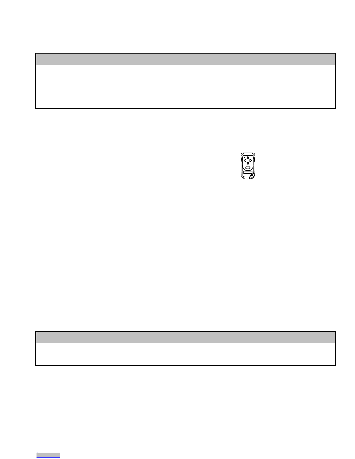
a. Observe the wireless transmitter. The Red light on the transmitter should turn
on whenever a button is pressed. If it does not, first check the internal battery
polarity, if correct then replace the transmitter.
b. Disconnect the 12 Volt DC power from the spotlight. Reconnect the 12 Volt DC
power to the spotlight. Press the green On/Off button 2-3 times within 5
seconds of applying power to the light.
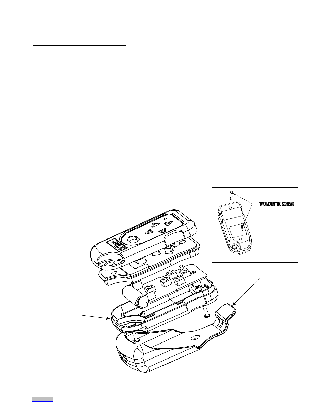
c. Remove the 4 bolts that fasten the spotlight onto the mounting surface and
gently lift the unit until you can see inside its base. Avoid cutting any wires.
Gently inspect the wiring inside the base for broken connections. Examine the
circuit board for loosened plug connectors, blackened components or
corrosion. Replace the circuit board if it appears damaged. If there are no
loose wires or signs of water penetration, re-install the spotlight and then
replace the wireless transmitter. If there are signs of damage,
contact The Guest Company Service Department for advice.
See page 12 for contact information.
Have available information on how and where the spotlight was installed.
Downloaded from Arrow.com.Downloaded from Arrow.com.Downloaded from Arrow.com.Downloaded from Arrow.com.Downloaded from Arrow.com.Downloaded from Arrow.com.Downloaded from Arrow.com.Downloaded from Arrow.com.Downloaded from Arrow.com.Downloaded from Arrow.com.

11
4. If the spotl ght moves properly but does not l ght, examine the halogen bulb.
Replace it if it appears discolored or broken. If the bulb appears to be normal,
test for a faulty relay by listening at the base of the light while someone else
activates the bulb using the control. If no "click" is audible, or if a "chattering"
sound is heard, replace the relay. Note: Low voltage or a faulty circuit board
may cause similar symptoms.
5. If the spotl ght w ll not move left or r ght but operates normally otherwise,
listen at the base of the light while someone else presses the left/right directional
buttons. If the lower motor makes no sound when it is activated, replace the
lower motor.
If your l ght has a problem that s not descr bed above, contact the Guest
Service Department for advice (see page 12 for contact information). e sure to
have available a detailed description of the problem, proof of purchase (if requesting
warranty service), and your daytime telephone, fax number, or e-mail address
.
FCC Notification
Changes or modifications not expressly approved by the party
responsible for compliance could void the user’s authority to operate the
equipment.
To comply with the FCC RF exposure compliance requirements, this
device and its antenna must not be co-located or operating in
conjunction with any other antenna or transmitter.
Downloaded from Arrow.com.Downloaded from Arrow.com.Downloaded from Arrow.com.Downloaded from Arrow.com.Downloaded from Arrow.com.Downloaded from Arrow.com.Downloaded from Arrow.com.Downloaded from Arrow.com.Downloaded from Arrow.com.Downloaded from Arrow.com.Downloaded from Arrow.com.

12
LIMITED WARRANTY
For one (1) year from the date of original purchase, The Guest Co., Inc. will, at its discretion, repair
or replace for the original consumer, free of charge, any parts found defective in material or
workmanship. All transportation charges under this warranty must be borne by the consumer.
Proof of purchase is required: a computerized register receipt is required. Hand written receipts are
not accepted for warranty proof of purchase. In the absence of a receipt, warranty period will be
calculated from date of manufacture printed or stamped on the product.
THERE IS NO OTHER EXPRESSED WARRANTY. IMPLIED WARRANTIES, INCLUDING THOSE
OF MERCHANTA ILITY AND FITNESS FOR A PARTICULAR PURPOSE, ARE LIMITED TO ONE
YEAR FROM THE DATE OF PURCHASE. THIS IS THE EXCLUSIVE REMEDY AND
CONSEQUENTIAL DAMAGES ARE EXCLUDED WHERE PERMITTED Y LAW.
Fax: (707) 226-9670 Website: www.marinco.com
730199 Rev 3429
Downloaded from Arrow.com.Downloaded from Arrow.com.Downloaded from Arrow.com.Downloaded from Arrow.com.Downloaded from Arrow.com.Downloaded from Arrow.com.Downloaded from Arrow.com.Downloaded from Arrow.com.Downloaded from Arrow.com.Downloaded from Arrow.com.Downloaded from Arrow.com.Downloaded from Arrow.com.
Table of contents
Popular Transmitter manuals by other brands

DLO
DLO TuneStik quick start guide

Emerson
Emerson CSI 9420 Reference manual

Tele Radio
Tele Radio T60-T8-53 installation instructions

Conversor
Conversor MultiPack user guide

Metal Samples
Metal Samples CORR VELOX MS2801E Operator's manual

Lectronics
Lectronics Digital Hybrid Wireless HHa-941 instruction manual

Aplisens
Aplisens LI-24L user manual

Avalon RF
Avalon RF OTX627 User's guide & operating manual

Becker
Becker CentronicPLUS SWC541A PLUS Assembly and operating instructions

Vaisala
Vaisala WAC155 user guide

Emerson
Emerson Rosemount 3101 Reference manual

Broadcast Electronics
Broadcast Electronics AM-500A manual