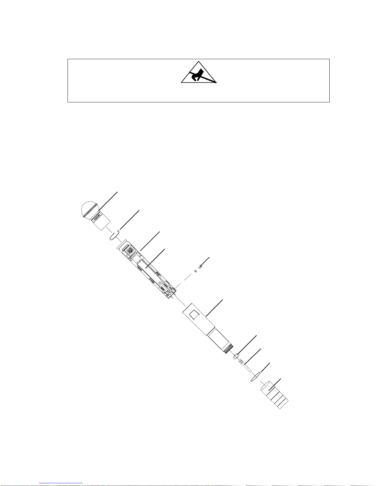
Shure U2 Hand-Held UHF Transmitter
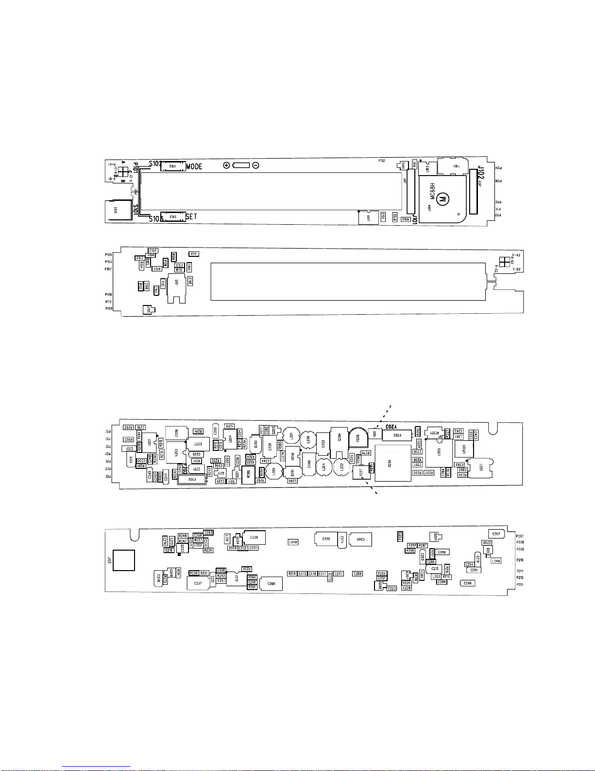
Circuit Description25B1022 (AG) 3
ence from external rf fields. Regulated 5 Vdc power from the dc/dc con-
verter ensures frequency stability even if the battery voltage drops.
The VCO is capable of tuning from 782 to 810 MHz with a 1 to 4 V
tuning voltage range. At the output of VCO U206, the rf signal splits into
two paths. The output of the VCO is coupled by C207 to the frequency
control pin of synthesizer U205.
The synthesizer’s internal circuitry divides the signal as necessary to
the desired reference frequency of 125 kHz. The synthesizer contains a
quartz-controlled reference oscillator circuit operating from a 4.0 MHz
crystal, Y203, that is adjusted by means of trimmer VC201.
The transmitter output frequency is user-selectable in pre-set
increments. The size of the increment and the overall frequency range
depend on the model (KK, JB, MB, MC, MD, etc.). Frequency selection
is made via microprocessor U104, which interfaces with the user through
the mode/select switches.
The output of the synthesizer is a series of pulses which are
integrated by a passive loop filter, R226, C231, R251, C237, R243, and
C257, to produce a control voltage signal. The control voltage signal is
then connected to the VCO through amplifier U210A which is used to
isolate the PLL filter from the audio modulation signals.
The VCO output is also coupled to an rf power resistive pad consist-
ing of R255, R256, R257, R258, and an LC-matching network containing
C270, L202, and C217. The rf power amplifier, a dual gate MESFET,
Q203, is fixed tuned, and configured as a common source device.
Amplifier stability is obtained through resistive loading on input R237.
The output of Q203 contains a low-pass matching network, L207, and
LC-type low pass filter, LP201, providing a high degree of spectral purity.
The output of the low-pass filter feeds a microwave isolator that reduces
the production of reverse third-order intermodulation products.
The transmitter is capable of delivering +10 dBm (10 mW), maxi-
mum to the 50 Ωhelical antenna. During transmitter power up and fre-
quency selection, the rf power is muted by bringing the base of Q209
high. This provides approximately 45 dB rf attenuation until the PLL has
locked.
The transmitter rf is then unmuted by bringing the base of Q209 low.
During transmitter power off conditions, voltage is first removed from the
VCO by bringing the base of Q208 high. In this way, the transmitter
carrier signal is not allowed to drift off frequency during power on or
power off conditions.
U2 Display Board
The Display Board consists of following circuitry blocks:
Microcontroller Section
The microcontroller section consists of microcontroller U104 and the
liquid crystal display (LCD). The microcontroller has an on-board LCD
driver. R104, R105, and R107 supply the microcontroller with the LCD
drive voltage for a 4-plex drive.
The LCD indicates the UHF frequency group and channel, and also
has a battery fuel gauge. A 4.000 MHz oscillator, Y101, provides the