Matsushita Electric EP1015-U1 User manual

ORDERNO.HPD0110U00C1
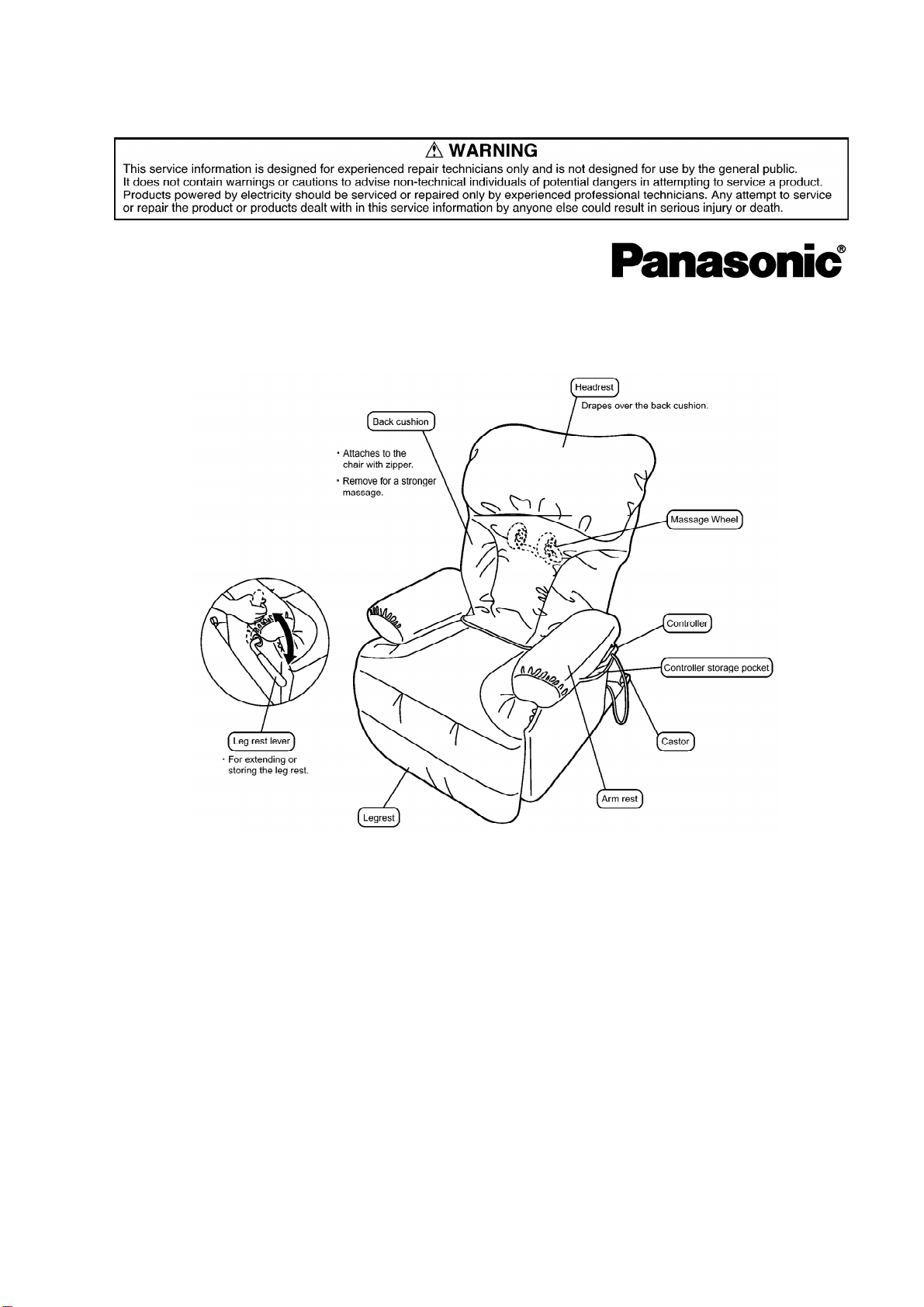
MASSAGELOUNGER
EP1015-U1
SPECIFICATIONS
SPECIFICATIONS
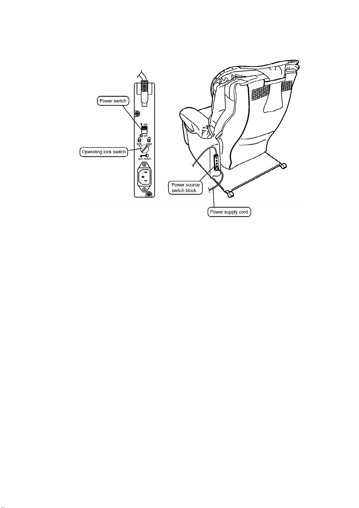
Power source : 120V AC, 60Hz
Power consumption : 200W
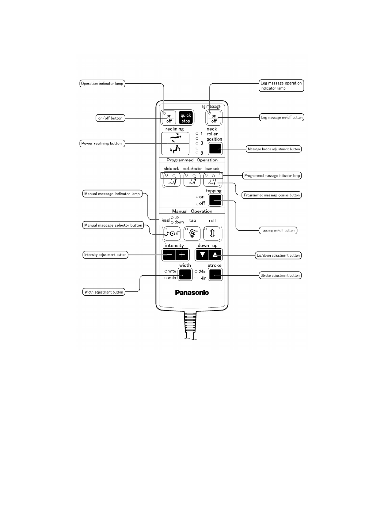
Kneading speed : Approx. 28 times/min.
Tapping speed : Approx. 500 times/min.(per side)
Rolling massagespeed : Approx. 1cycleevery37 sec.
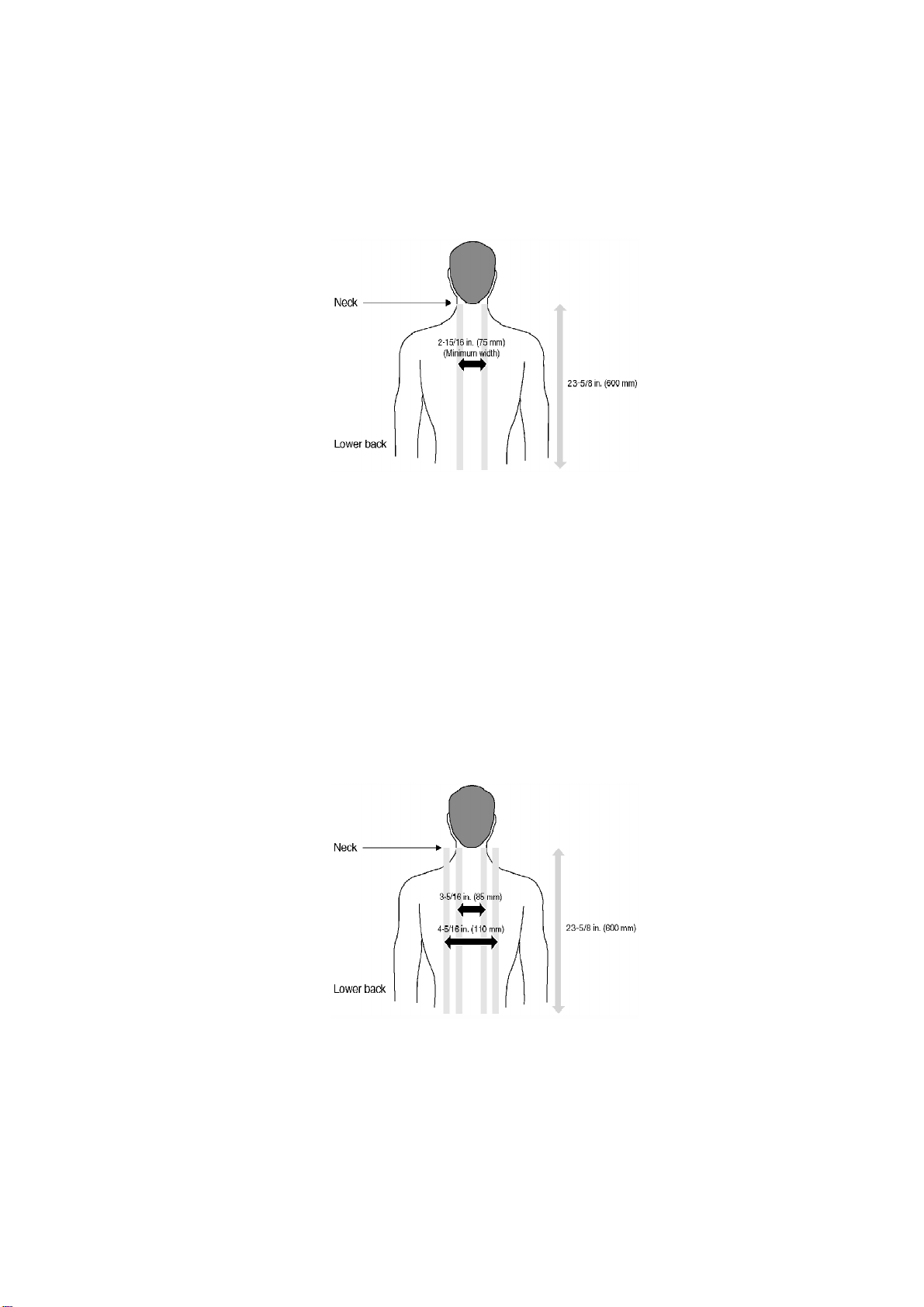
Massaging width : Shoulder/lower back section : Approx. 2-15/16 in. (75mm)
Back rolling width/tapping width: Narrow: Approx. 3-5/16 in. (85mm) / : Wide: Approx. 4-5/16 in. (110mm)
Massageheadsup/downtravel : Approx. 23-5/8in. (600mm)
Regional back rolling : Automaticrepetition withinapprox. 4-3/4in. (120mm) range
Intensityadjustment : Adjustsmassageheadprotrusion steplesslywithinapprox. 1-3/4in.(45mm) range
Shoulder position adjustment : 5steps
Automaticshut-off : Approx. 15 min.
Dimensions(H xWxD) : Not reclinedand legrest retracted: 41-11/32X34-41/64X40-35/64 in.(
1050X880X1030mm)
/ Reclinedand legrest extended: 29-9/64X34-41/64X68-7/64 in.(740X880X1730mm)
Reclining angle : Approx. 123° to160°
Weight : 121 lbs. (55kg)
Accessories : Back cushion, Headrest, Cushion pad
Maximumuser weight : 264lbs.(120kg).
2001 Matsushita ElectricWorks, Ltd. All rights reserved.
Unauthorized copying and distribution isaviolation of law.
1

1. Components identification
1.1. Massage lounger
2

1.2. Controller
3

2. Massage range (movement range of massage
wheels)
2.1. Upward massage, Downward massage, Kneading rolling,
Regional kneading rolling
Widthcannot be adjusted
Neck towaist : width75mm (minimum)
Intensityadjustment
4

Upwardand downwardmassage (fromgentle tostrong) :45mm-wide adjustabilitywhere
massage heads pushout towardbodyas intensityincreases.Others (fromgentle tostrong) :
15mm-wide adjustabilitywhere massage heads pushout towardbodyas intensityincreases.
2.2. Tapping, Rolling, Regional rolling, Tapping rolling, Regional
tapping rolling
Widthadjustment
Neck towaist : Massage range width: 3-5/16 in. or4-5/16 in. (85mm or110mm)
Intensityadjustment
Tapping : 45mm-wide adjustabilitywhere massage heads pushout towardbodyas intensity
increases.
Others : 15mm-wide adjustabilitywhere massage heads pushout towardbodyas intensity
increases.
3. Turning on the power
3.1. Turning on the power
5

Timer
Whenthe on/off button is pushed, a timerbegins toprevent overuse. Afterapproximately15
minutes, time expires and the massage wheel goes intostrage position.
4. Required tools
6

5. Actual wiring diagram
7

6. Display method of massage block total use time
and operation time
Total use time
While pushing the whole back, neck shoulderand lowerback mode programmedoperation
buttons simultaneiously, turnon the powerswitchand continue toholdthe buttons for
approximately5 seconds. Release afterthe on/off LED lights up.
*Whenreplacing the MainCircuit PCB, the use time is countedtozerobecause the use time is
memoriedinMainCircuit PCB.
*Whenpushing on/off button, the operation returns tonormal mode.
8

Displaymethod
Displayit byutilizing LEDs of controller.
Time displayof 5 - 5115 hours possible.
To readthe eachoperation function.Afterreading the total use time and pushthe following
button, you canreadthe eachoperation funtion use time as same displaymethod of total use
time.
7. Motion of the clutch and belt based on various
massager operations.
Massageroperation and belt motion
9

Massageroperation and clutchmotion
8. Massager up/down detection gear adjustment
method
10

Whenthe massageris removedfromthe chair, the position of the up/downdetection gear
changes, resulting ina change of the up/downstop position.
Wheninstalling the massageron the back frame, be sure toadjust the position withthe up/
downdetection gear.
Up/downdetection gearposition adjustment procedure
To make anadjustment, refertothe massagerremoving method (the back frame is tiltedfrom
the chair).
1. Before mounting, the massager on the back frame must be moved
downto the lowest position bysetting the controller manual
operation UP/DOWNbutton to DOWN.
2. Mount the massager on the lowest position of the back frame.
3. Turn the hex nut M6 counterclockwise and move the massager
upward.
4. Make sure that the massager has been mounted horizontallyby
moving the massager to the position showninthe Figure.
*Unless the massager has been mounted horizontally, an
abnormal sound or problem mayoccur.
5. Move itup to the highest position(until the massager stops) by
setting the controller manual operation UP/DOWNbutton to UP.
6. Peeping into the square holeof the back frame, check the
position of the massager to adjust.
*One thread of the up/downdetection gear gives astroke change
of 4mm.
Whenthe massagerhas beenraisedexcessively: Turnthe up/downdetection gearclockwise to
adjust.
Whenthe massagerhas beenloweredexcessively: Turnthe up/downdetection gear
counterclockwise toadjust.
Whileadjusting the distance between the square holeand Guide
roller assy. to 30~35mm, check byusing the up/downadjustment
button found on the manual operation panel of the controller.
7. Install the rail piece Aand B, and tighten uniformlythe set screws
(left and right, 3pcs. each).
11

8. Using the manual operation of the controller, conduct the rolling
operation. Set the massage heads adjustment switch to level 1,
and check the up/downstroke.
9. Removing the massage block
9.1. Removing the rear cover
1. Unzipthe back cushion zipperand remove the back / cushion.
2. Unzipthe rearcoverfastenerfromthe bottomof left side.
12

3. Pull the chairdownbackwardand cut insulatedties and remove the plastic clip.
9.2. Removing the massager
1. Remove the twoinstallation screwsfrom the massager cover, and
take off the cover and remove the Cover clip.
*Cover clipisavailableto remove onlyafter taking off the cover.
2. Remove twosnap pins connecting Ottoman Power Lift Unitand
Connecting Linkage to Back frame, and push downthe seatback
to the front part for easyrepaire.
*Inspection and repairare done after placing the chairas
explained in1. and 2. above.
3. Remove the rail piece set screws, 3pieces (left and right) shown
inFigure, and remove the rail pieces Aand B.
4. When the massager moves up and down(normally), move itdown
to the lowest position bysetting the controller manual operation
up/downbutton to "DOWN", and then turn clockwise the up/down
13

clutch hex nut M6 (see Figure) to move to the position where the
Pinion Aand Bblock isvisiblefrom the back frame.
*When the massager failsto move up and down, turn clockwise
the hex nut M6 of up/downclutch.
(The massager can be moved byattaching the hex socket 10 (for
nut 6mm) to arechargeabledrill driver.)
5. Cut the cabletieas shownfigure and remove the twoconnectors
(red, white) of the connecting cord for power supplyand the
connecting cord for controller connected massager and unscrew
the ground cord of the connecting cord for power supply, remove
one screw fixing the massager side cord Fitting Band Cord wire D
and remove twocords from the massager.
14

15

10. Disassembly (massager) and assembly
The disassemblysteps 10.1 to10.3 canbe done without removing the massagerfromthe chair
(please work withthe / connectorcordremoved).
10.1. Removing the motor
1. Remove the cabletie(medium), and remove the motor lead wire
connector(white).
2. Remove the massage belt, up/downbeltand intensityadjustment
16

belt.
3. Remove the motor fitting set screw Ato D, and remove the motor
and tapping belt.
10.2. Removing the tapping shaft assembly
1. Cut all the insulated ties bundling each sensor and lead wires
with the aidof anipper, and remove the lead wires bundled to the
wire saddles (medium, large).
2. Remove all the connectors to the maincircuitboard.
3. Remove the massage belt, up/downbeltand intensityadjustment
belt.
4. Remove the motor fitting set screwsAto D, and remove the motor
and tapping belt.
5. Remove the shieldpanel (fitted to the circuit) set screw Eto J,
and remove the shieldpanel and eccentricshaft spring.
6. Remove the Ktype stop ring byusing flat head driver.
7. Remove the screw Kto Mand remove the intensityadjustment
block.
8. Remove the Pro tektite cover for eccentriclink set screwsNwith
aspanner, and remove the Pro tektite cover for eccentriclink and
17

remove another screw O and the Pro tektite cover for eccentric
link.
9. Remove the guide plate for motor set screwsPto Rand the guide
plate for gearbox set screwsSto V.
10. Slide out the tapping shaft assemblywith tapping clutch and the
guide plate for gearbox.
*Caution forassembling the protektite coverforeccentric spring.
<Assemblyprocedure>
1. The tapping shaft assemblyshouldbe mounted on massage
mechanism, and put the grease(WEP001Y8957) on the spring
setting holeof pro tektite cover for eccentricspring and set the
one end of spring to holeas shownFigure.
2. Put the grease(WEP001Y8957) on the spring setting holeof Shield
panel for PCB and set the other end of spring to holeof Shield
panel for PCB.
3. Mount the Shieldpanel for PCB on massage mechanism.
18

10.3. Removing the gear box
1. Perform removal of steps 1to 10 of "10.2. Removing the tapping
shaft assembly".
2. Remove one screw and the Capacitor.
3. Remove the transformer set screw, and remove the transformer
and remove the base for transformer set screw Wto Yand remove
the base for transformer.
4. Remove the screw Zand Up/downdetector P.C.B.
Remove the gear box screwsato d.
19

5. After removing the screws, the massage clutch, up/downclutch
and intermediate gear block can be removed.
*Take care sothat the grease does not stick tothe massage clutchand up/downclutchpulleys.
If grease sticks, remove it withalcohol.
*The massage clutchand up/downclutchhave similarshapes. The leadwires are the same gray
color, soplease choose basedon connectorcolor.
10.4. Removing the massage wheel unitset (right, left)
(Remove the massagerfromthe chairbefore beginning the following procedure.)
1. Perform steps 1to 10 insection, "10.2Removing the tapping shaft
assembly".
2. Remove screwsaand fwhich connect the gear box and main
frame, and remove the mainframe. (When removing the main
frame, turn the massage clutch hex nut so that the massage width
isat its minimum.)
3. Remove the up/downshaft boltof the pinion Bblock with the box
driver, and remove the pinion Bblock.
4. Remove the pipe bearing, and remove the Massage position plate.
(Take care not to break the Massage position plate.)
20
Table of contents
Other Matsushita Electric Massager manuals