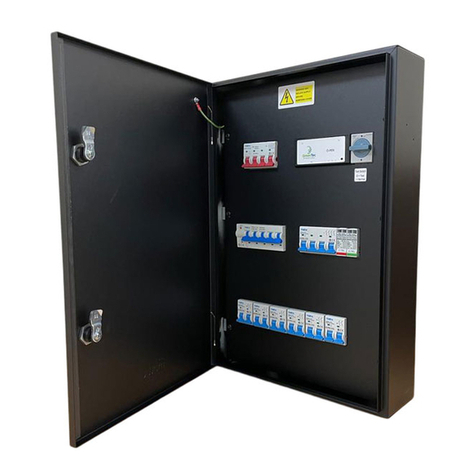
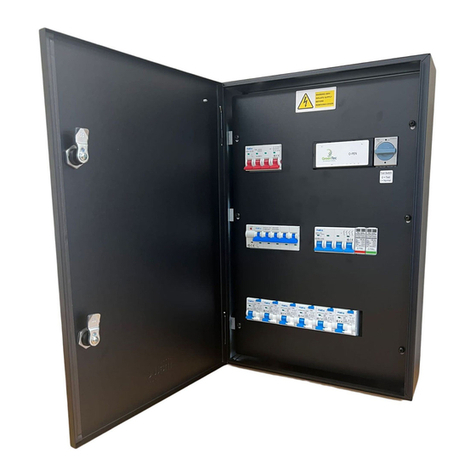
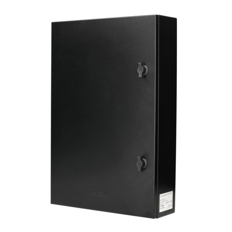
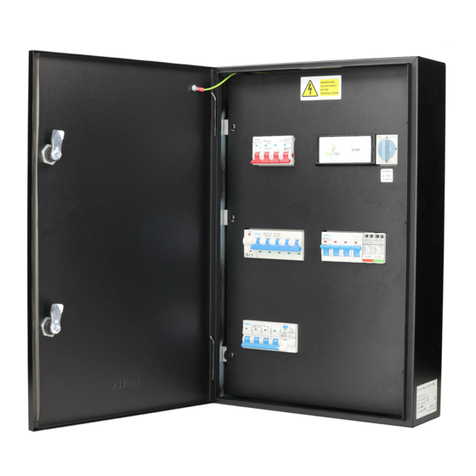
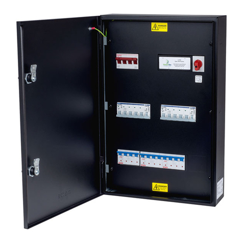
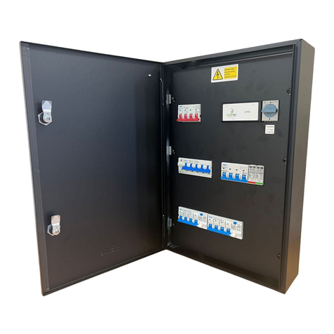
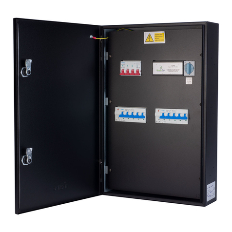
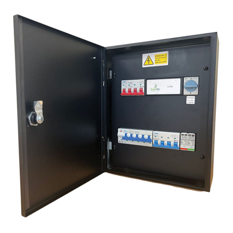
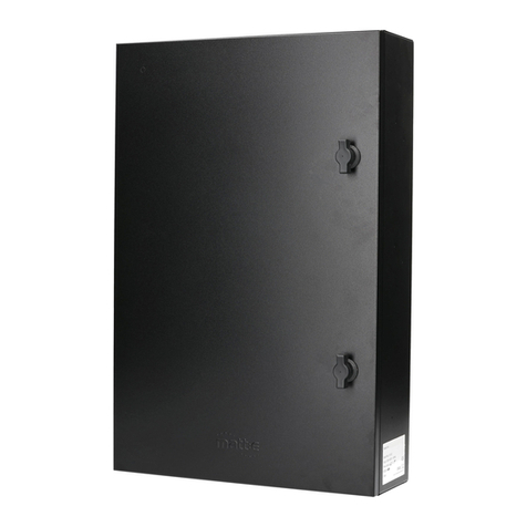
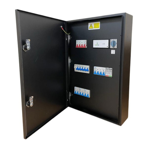
Single-phase EV charger protection unit
4 | P a g e
Introduction
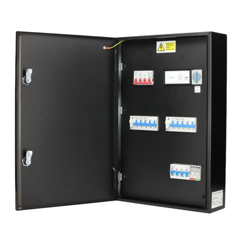
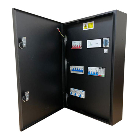
The matt:e range of Single Phase Electric Vehicle Charger Protection units are designed to protect
Electric Vehicle Charging equipment when installed onto single-phase PME infrastructures .
All units incorporate an electronic detection circuit and 3 pole contactor. The T version has a double pole
isolator and a single terminal on the incoming side of the unit. The M version has a double pole MCB and
a single terminal on the incoming side of the unit. The R version has a double pole Type A RCBO and a
single terminal on the incoming side of the unit.
The IP-EVCP-R(C) versions are rated to be connected directly to the supply meter tails via suitable
connectors. All other versions must be connected via the Consumer Distribution Board or ‘Garage
Board’ and suitable protective device.
The Current Curtailment versions are supplied with a split core CT for installing on the main incoming
supply cable to the property. See page 7 for connection details.
On detection of fault conditions, the electronic circuit disconnects the EV charger from the incoming
supply including CPC by de-energising the contactor. The isolation contactor is certified to BS EN 60947-
4-1 and complies with the requirements of BS: 7671 18th Edition.
The matt:e IP-EVCP technology does not require earth rods or measuring electrodes to function
correctly.
The units are designed to be installed between the service providers meter / distribution board and the
Electric Vehicle Charger. The unit must be mounted securely to a solid surface with the lid hinges at the
left.
The installation location should well-ventilated and out of direct sunlight.
Please refer to the diagrams on the following pages for the dimensions and mounting arrangements of
the units.
