www.valontechnology.com 5 5/13/2016
Discharging
Storage short term
Long term storage
0~60 ⁰C
-20 ~+45 ⁰C
20 ⁰ ± 5 ⁰ C
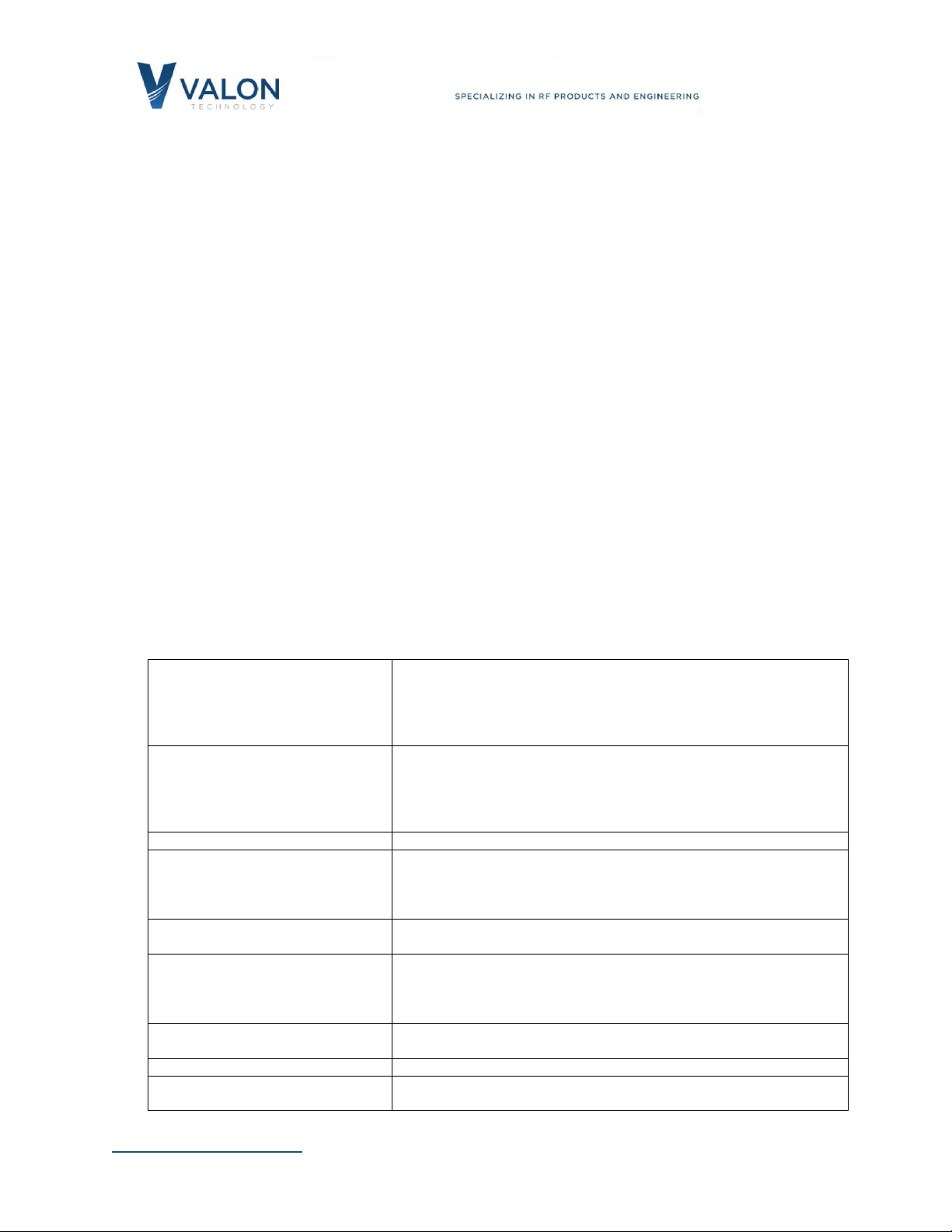
Battery
Battery Life
Self-discharge rate
Single cell (3.7V) Lithium Polymer 2000mAh Mikoe 1120 <40mg.
>300 charge cycles
>90% capacity after 30days at 20±5⁰C
3Safety
3.1 Battery Care
The UPS6V-2 contains a single cell lithium-ion polymer rechargeable battery. LIP batteries can
be dangerous if mishandled. Do not open the case except to replace the battery. Replace only
with the recommended replacement battery. Do not cut or pierce the battery. Do not unwrap
the battery covering or attempt to remove the protection circuit. Dispose of the battery in a
safe and approved way. Valon Technology is not responsible for any damage this equipment
causes to any other equipment connected to or used with it in any way.
3.2 RoHS (Restriction of the use of certain Hazardous Substances)
With the exception of the battery, the UPS6V-2 module is manufactured using all RoHS
compliant components and RoHS compliant printed circuit board processing. The case is
manufactured using only aluminum with steel fasteners.
Valon Technology, LLC certifies that the UPS6V-2 is RoHS compliant and conforms with the
requirements of EC directive 2002/95/EC (RoHS) by having no intentional addition of Lead (Pb),
Cadmium (Cd), Mercury (Hg), Hexavalent Chromium (Cr), Polybrominated Biphenyls (PBB),
Polybrominated Diphenyl Ethers (PBDE), and any trace impurities of these substances are below
the threshold limits as specified by the RoHS directive, specifically Cr+6, Hg, Pb, PBB, PBDE do
not exceed 1000 ppm (0.1%) and Cd does not exceed 100 ppm (0.01%).
3.3 FCC Part 15
The UPS6V-2 is considered an industrial component and is intended to be incorporated into
customer supplied equipment and is therefore exempt from FCC Part 15.
4Power Connections
4.1 Input Power Connection
Input Power connections are made to the dc power supply using the supplied Hirose 2-pin plug
and 20" pig-tail cable assembly. The optimum input voltage for full performance with a
synthesizer or similar Valon load is 6.0 Volts minimum. Make sure the power adapter or power
supply can deliver the required current both for the load and the charger. For example, if the
load is a 5009 requiring typically 540mA and the battery is being charged, then the power supply
or ac adapter must be able to deliver ~1.6Amps.
Do not intentionally apply reverse polarity to the power input connector. However, if you do,
no damage will occur and no current will be drawn. Disconnect and examine your connections
and reapply power.