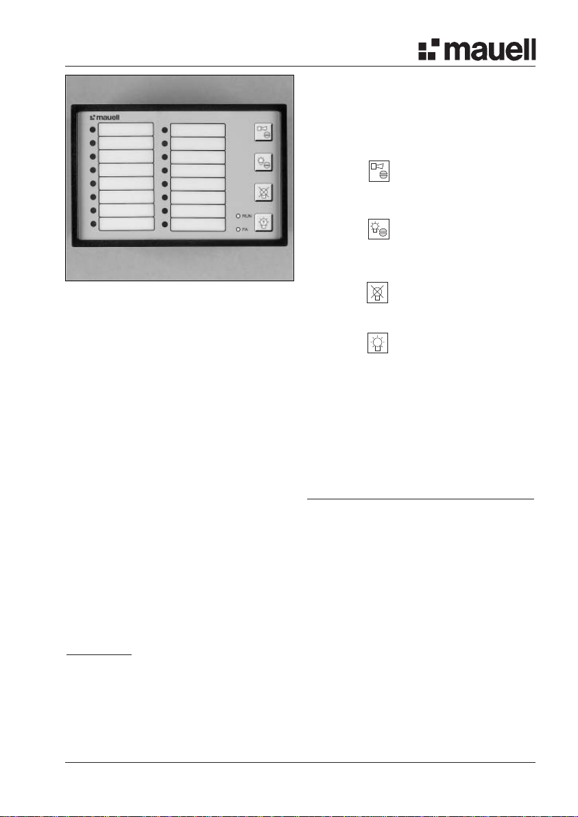
ME30 infobox connect
4infobox connect
Terminal Assignment
Plug-in Pin Designation Meaning
connector
X01 1 UV(+) Supply voltage (positive terminal at DC)
2UV(-) Supply voltage (negative terminal at DC)
3ERDE Supply voltage Earth connection
X02 1 UH+ Emergency supply voltage, positive terminal
2UH- Emergency supply voltage, negative terminal
3HQ External pushb. input Horn acknowledgement
4Q External pushb. input Message acknowledgement
5LÖ External pushb. input Delete message
6LT External pushb. input Lamp test
X11 1 to 9 ME (+) Message input Contact supply
Group 1 (positive terminal at DC)
X11 (at 1 RA 1 Group 1 Message transmission relay contact 1
optional to
relay 8 RA 8 Group 1 Message transmission relay contact 8
output) 9 RA W Group 1 Message transmission relay contact Root contact
X12 1 ME 1 Group 1 Message input 1 (positive terminal at DC)
to
8ME 8 Group 1 Message input 8 (positive terminal at DC)
9ME (-) Group 1 Message inputs Group root (negative term. at DC)
X13 1 MR-Ö NC contact Annunciator relay output (*1)
2MR-S NO contact Annunciator relay output (*1)
3W Relay root contact
4MR-Ö NC contact Annunciator relay output (*2)
5MR-S NO contact Annunciator relay output (*2)
X21 1 to 9 ME(+) Group 2 Message inputs Contact supply
X21 (opt.) 1 to 9 RA 9 to RA16 Group 2 Message transmission relay contacts
X22 1 to 9 ME 9 to ME 16 Group 2 Message inputs
X23 1 to 5 MR Group 2 Annunciator relay outputs (*3)
X31 1 to 9 ME(+) Group 3 Message inputs Contact supply
X31 (option) 1 to 9 RA 17 to RA 24 Group 3 Message transmission relay contacts
X32 1 to 9 ME 17 to ME 24 Group 3 Message inputs
X33 1 to 5 MR Group 3 Annunciator relay outputs (*3)
X41 1 to 9 ME(+) Group 4 Message inputs Contact supply
X41 (option) 1 to 9 RA 25 to RA 32 Group 4 Message transmission relay contacts
X42 1 to 9 ME 25 to ME 32 Group 4 Message inputs
X43 1 to 5 MR Group 4 Annunciator relay outputs (*3)
X51 1 to 9 ME(+) Group 5 Message inputs Contact supply
X51 (option) 1 to 9 RA 33 to RA 40 Group 5 Message transmission relay contacts
X52 1 to 9 ME 33 to ME 40 Group 5 Message inputs
X53 1 to 5 MR Group 5 Annunciator relay outputs (*3)