MAUTING Junior 03 User manual

Operating Instructions
Smoking Chamber
Junior 03
Production Number: 081/11
Year of Production:2011

Smokehouse MAUTING Junior Date:
1.7.2006
Worked out:
Fila Petr
Checked by:
Bielak Antonin Ing.
Approved by:
Bielak Antonin Ing.
Version No: 3 Page:
2of 22
Instruction manual
CONTENT:
1. INTRODUCTION......................................................................................................................................... 3
1.1. Usage ................................................................................................................................................... 3
2. GENERAL INSTRUCTIONS....................................................................................................................... 3
2.1. Safety................................................................................................................................................... 3
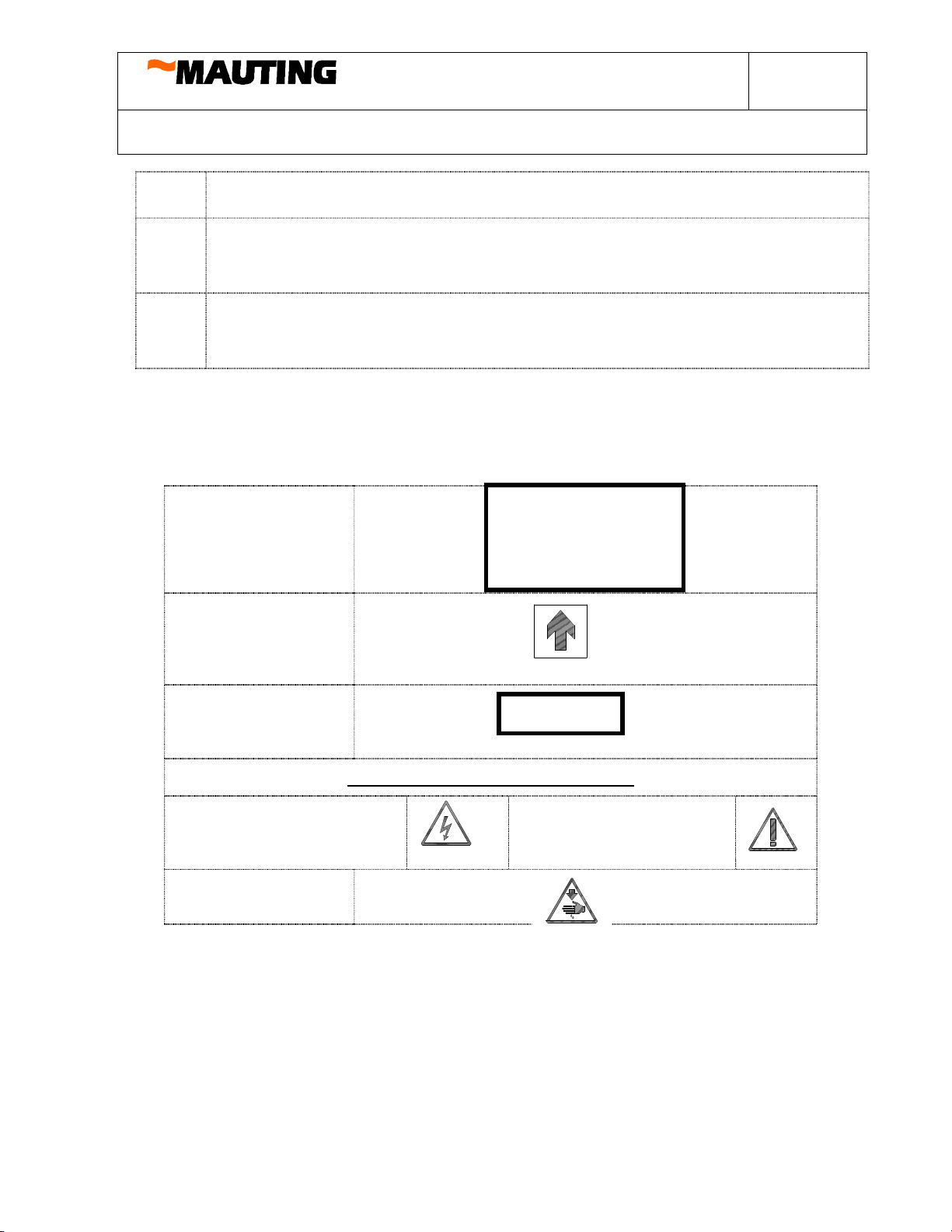
2.2. Symbol specifications.......................................................................................................................... 3
2.3. Safety regulations –organization measures......................................................................................... 4
2.4. Safety regulations –protective instruments ......................................................................................... 4
2.5. Safety regulations –device operator.................................................................................................... 4
2.6. Safety regulations –work with smoke generator................................................................................. 5
2.7. Safety regulations by maintainanace, cleaning and troubleshooting.................................................... 5
2.8. Warning labels placement.................................................................................................................... 6
2.9. List of safety devices and their role ..................................................................................................... 6
3. TECHNICAL DESCRIPTION...................................................................................................................... 7
3.1. Operation conditions............................................................................................................................ 7
3.2. Technical parameters ........................................................................................................................... 7
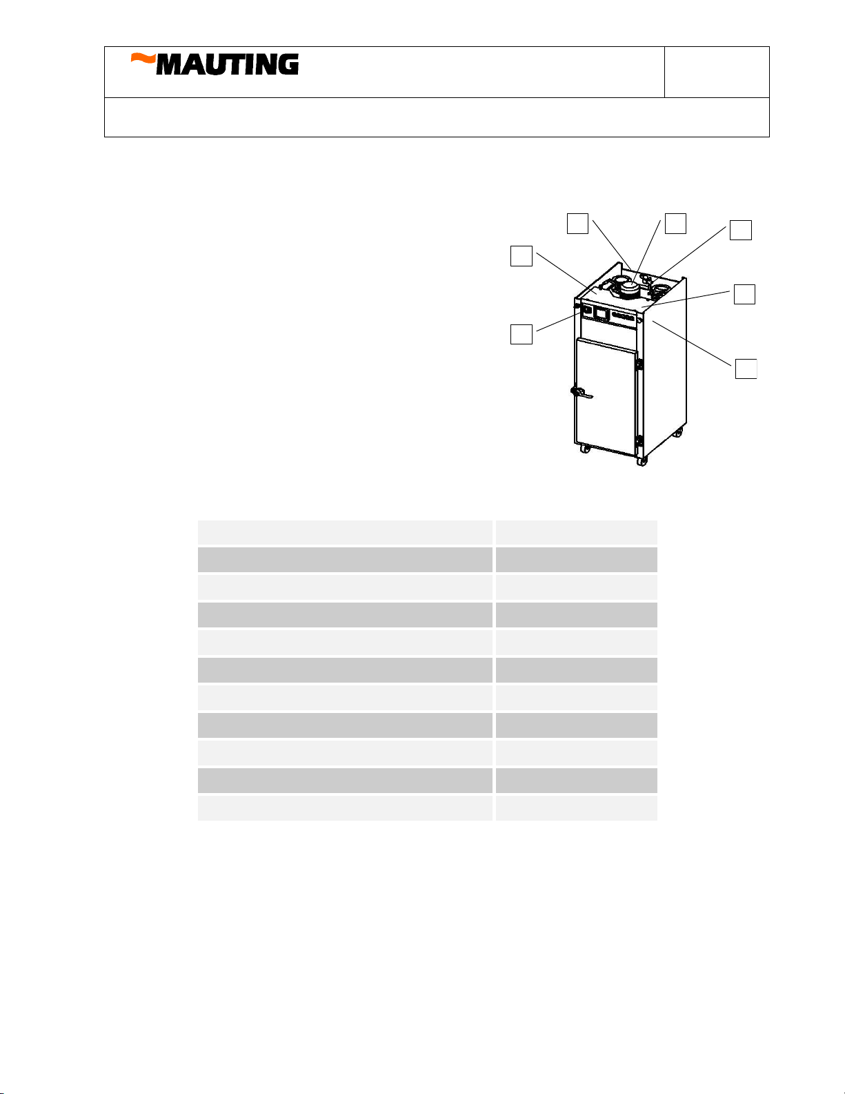
3.3. Description........................................................................................................................................... 7
3.4. Material.............................................................................................................................................. 10
3.5. Operator ............................................................................................................................................. 11
4. INSTALLATION OF CHAMBER ............................................................................................................. 14
5. ACCEPTANCE, DELIVERY..................................................................................................................... 15
6. ORDERING ................................................................................................................................................ 15
7. PACKAGING, TRANSPORTATION, STORAGE.................................................................................... 16
8. CLEANING................................................................................................................................................. 16
8.1. Technological process of chamber cleaning ...................................................................................... 16
8.2. Technological process of smoke generator cleaning.......................................................................... 16
9. MAINTAINACE AND TROUBLESHOOTING........................................................................................ 17
9.1. Periodic service and inspection schedule........................................................................................... 17
10. MALFUNCTIONS AND THEIR REPAIRS ......................................................................................... 18
11. SPARE PART LIST ............................................................................................................................... 20
12. GUARANTEE........................................................................................................................................ 20
13. REGULATIONS AND STANDARDS.................................................................................................. 21
14. PICTURES AND APPENDIX:.............................................................................................................. 21
15. REMARKS............................................................................................................................................. 22

Smokehouse MAUTING Junior Date:
1.7.2006
Worked out:
Fila Petr
Checked by:
Bielak Antonin Ing.
Approved by:
Bielak Antonin Ing.
Version No: 3 Page:
3of 22
Instruction manual
1. INTRODUCTION
1.1.Usage
Smoking chamber MAUTING Junior is equipment designed for small meat processing
plants and also for restaurants. It makes possible to heat treatment of meat products, e.g.
drying, smoking, cooking and roasting up to 160°C in one cycle without further
manipulation, with manual control of flaps, glowing (smoking) and moistening. It
means that a microprocessor unit according to a chosen program controls technological
process. User can easily create his own programs according to his needs –it means
setting of chamber temperature, core temperature and time of processing. The smoking
chamber is electrically heated. Another way of usage must be consulted with the
manufacturer.
This instruction manual
·is an integral part of the chamber and has to be permanently placed in the
process room
·is designed for a qualified stuff
·contents the most important advices and warnings concerning the putting in
operation and maintenance of the equipment
2. GENERAL INSTRUCTIONS
2.1. Safety
The machine is equipped with accessories not only for operator security but for the
machine protection too. These precautions cannot cover all possible situations.
Therefore it is necessary that operator, earlier than puts the chamber in operation, will
have red through this manual and understood to it. By this way the operator can avoid
mistakes in process. In addition the operator has to be aware of another dangerous that
can appear in relation to environment and materials.
Equipment is possible to use only
·in determined range of usage
·in faultless technically safe condition
·with following instructions in this manual
Defects, that can affect safety, must be taken away immediately.
2.2. Symbol specifications
There are three kinds of safety directions in this instruction manual
·
·This symbol gives you warning that disobedience of this
order can cause from serious bodily harms to death risk

Smokehouse MAUTING Junior Date:
1.7.2006
Worked out:
Fila Petr
Checked by:
Bielak Antonin Ing.
Approved by:
Bielak Antonin Ing.
Version No: 3 Page:
4of 22
Instruction manual
·
·This symbol gives you warning that disobedience of this
order could cause life threatening by electrical current
·
·This symbol gives you warning that disobedience of this
order could cause damage or destruction of the equipment or
injuries
2.3. Safety regulations –organization measures
·Do not try to start the machine until you have read all instructions delivered with the
chamber and understood to all features and processes.
·The smoking chamber must not run in a room where some easily combustible matters or
explosives are processed or are on stock.
·Do not modify the chamber in a way, that could endanger its safety.
·Ensure always enough working space and free access to the control unit. Provide
sufficient lighting of the working area.
·Keep clean the space around the machine (continuously remove spilled water and grease
on the floor, be aware of the slipping hazard).
·If you doubt about the manufacturing process, contact the responsible person.
·The equipment can be run only if all safety accessories are fully working.
·Follow all fire precautions.
·It is recommended to not run the machine during a storm.
·Do not work with the equipment under influence of drugs or alcohol.
2.4. Safety regulations –protective instruments
·Operator is obliged to use protective instruments by opening the chamber door of running
machine.
·Do not set the control unit with protective gloves on, it could cause bad choice or another
mistake.
2.5. Safety regulations –device operator
·Check and make sure that the machine is in a good state before the start.
·Remember the positioning of the main power switch.
·Make sure that display shows the required program of product, treated in the chamber.
·Learn the meaning of the individual push buttons on the control panel to avoid running
bad operation.
·Electrical control unit, transformer, engine and connection block are labelled as low
voltage equipment. Do not touch active parts in any case!
·Make sure that all protective shields of the terminal unit are installed before connection

Smokehouse MAUTING Junior Date:
1.7.2006
Worked out:
Fila Petr
Checked by:
Bielak Antonin Ing.
Approved by:
Bielak Antonin Ing.
Version No: 3 Page:
5of 22
Instruction manual
to the power supply. In case it is necessary to open the switchboard box or remove the
protective cover, switch off the main breaker.
·Do not switch on the machine if the protective covers are removed. Do not remove
protective shields in any case.
·Check regularly whether protective covers are mounted well and are not damaged. Repair
or exchange the broken cover.
·Check whether electrical cables are not damaged to avoid electric shock.
·Do not spray water to the switchboard box, control unit, electric heat exchanger, electric
motors, electromagnetic valves and cables to avoid electric shock.
·Do not open the switchboard box cover if the main power switch is on.
·In case you do not work with the chamber, switch off the power supply.
·By electricity failure, switch off the main supply
2.6. Safety regulations – work with smoke generator
·Clean the smoke generator regularly.
·Wooden chips in appropriate quantity must be present in the feeding hopper during the
glowing and smoking.
·Use the recommended size of the wooden chips 4 – 12 mm and humidity φ < 20%.
·Do not open the doors during the glowing and smoking.
·Pay attention to the high temperature in the chamber, smoke generator and smoke outlet.
2.7. Safety regulations by maintainanace, cleaning and troubleshooting
·Maintenance has to be provided by a qualified stuff in accordance to the directions of
the responsible person. Worker providing maintenance and allowed repairs has to know
in detail function of the machine, inclusive this manual. Late detection of failure and
incompetent or maintenance in poor quality could cause troubles and economical losses.
·
·Only entitled person with appropriate electro technical qualification may work with
electrical equipment.
·Switch off the main power before any maintenance works. It prevents start the machine
by another person. If it is necessary to have the power on, pay attention to higher safety.
·Check (in a short time after switch-off) by a multi meter or another suitable
measurement device to be sure that no residual voltage is present.
·Check, by exchange of fuse or circuit breaker, whether the new part has the right
nominal value (usage of a part with higher nominal value could damage the equipment)
·Do not start the machine until removed covers are on back to the right position.
·To avoid damage of the smoking chamber and also expiration of guarantee rights, use
only appropriate spare parts and do not neglect periodic maintenance.
·Use safety clothing, protective shield (goggles) and gloves by work.
·Check the results of maintenance by presence of the responsible person.

Smokehouse MAUTING Junior Date:
1.7.2006
Worked out:
Fila Petr
Checked by:
Bielak Antonin Ing.
Approved by:
Bielak Antonin Ing.
Version No: 3 Page:
6of 22
Instruction manual
·
Periodic maintenance and adjustment keep your equipment in a good condition.
Periodic interval of maintenance and service are quoted in the schedule.
·Follow the instructions and safety directives subscribed by producer of detergent.
·Use protective instruments subscribed by producer of detergent (safety clothing,
protective shield, goggles and gloves).
·Follow the safety instructions quoted on the labels fixed on the machine. Do not paint
over, dirty, damage or remove these warning labels. In case of damage or illegibility of
any, contact the manufacturer.
2.8. Warning labels placement
This machine is equipped by a safety accessory that protects operator and device. The
main safety equipment consists of main power supply breaker and protective covers.
There are informative and warning labels placed on the machine.
1. Label of Type:
2. Direction of
rotation:
3.
Incoming
pressure of water:
WARNING BY REMOVED COVER:
4.Danger of electric shock: 5.Danger of mechanical
hazard:
6.Accident hazard
2.9. List of safety devices and their role
A) Main supply switch –switches off machine from electricity
B) Breakers of electrical appliances –protect electrical devices from effect of
over current
MAUTING spol. s
r.o.
Type: UKM Junior
Weight: xxx kg
Production No: xxx/xx
Production year: xxxx/xx
Incoming pressure
min. 0,3 MPa

Smokehouse MAUTING Junior Date:
1.7.2006
Worked out:
Fila Petr
Checked by:
Bielak Antonin Ing.
Approved by:
Bielak Antonin Ing.
Version No: 3 Page:
7of 22
Instruction manual
4
3
4
1
2
B
A
3. TECHNICAL DESCRIPTION
3.1. Operation conditions
Electrical device is designed to flawless work
under following climatic conditions :
temperature from +5 to +30°C
relative humidity 60% by +30°C
or 90% by +20°C
Electric power of the device is quoted in the
electro technical documentation. The machine is
delivered for the electricity system 400/230V, 50
Hz. Other values have to be declared in the
contract of sale.
Nominal values, dimensions and connection
places are stated in the project drawing.
3.2. Technical parameters
Total electrical power consumption 10,8 kW
Input of heating element in smoke generator 0,7 kW
Input of heating elements in chamber 9 kW
Input of fan 1,1 kW
Dimensions :
width 620 mm
depth 800 mm
height 1780 mm
Total weight (empty chamber) 230 kg
Water connection G 1/4"
Diameter of smoke outlet 100 mm
3.3. Description
Smoking chamber Junior consists of welded housing and other parts that are screwed on it.
Housing of the chamber is created by side panels, rear panel, on it is fixed smoke generator,
floor, ceiling, which part is the fan with a gear, outlet flap, fresh air flap and water
distribution for humidification, and front bars serving for connections and fortifications of
ceiling and floor in the front part of the chamber housing.

Smokehouse MAUTING Junior Date:
1.7.2006
Worked out:
Fila Petr
Checked by:
Bielak Antonin Ing.
Approved by:
Bielak Antonin Ing.
Version No: 3 Page:
8of 22
Instruction manual
Another parts of the chamber are:
·Chamber door –serves for closing inward chamber ambient from surroundings. It is
made of mineral wool insulation, hinges, door handle and door seal.
·Smoke generator –serves for production of smoke. It consists of the heating element
which is placed above the ash tray and below the box with wooden chips. The smoke
generator is placed in the bottom part of the chamber. Smoke is created by glowing
wooden chips of hard wood on the red-hot heating element with the controlled access
of air. The wooden chips have to be stored in dry, well ventilated rooms. Injurants of
smoke stem if the temperature of glowing wooden chips is higher than 400oC. Special
scent and taste of smoke meat product are achieved by combination of phenols and
proteins in meat that interact with carboxylic acids contained in smoke. It is necessary
to stock the wooden chips in dry and well-ventilated room.
Picture 1 Description of smking chamber

Smokehouse MAUTING Junior Date:
1.7.2006
Worked out:
Fila Petr
Checked by:
Bielak Antonin Ing.
Approved by:
Bielak Antonin Ing.
Version No: 3 Page:
9of 22
Instruction manual
·Tray support –serves for fixation of trays, grids or smoking sticks
·Heating elements –have housing made of high quality stainless steel and are
fixed through the holes in the rear panel
·Side perforated plates –serve to streamline air flow to individual levels of trays
·Soffit –it is inserted inside, underneath the fan to streamline air flow, which is
sucked by the fan
·Switchboard box
There are placed all control, switch and breaker parts. Switchboard box is situated in
the upper part of the chamber, close to the control unit. On the front side of the control
unit is the main power switch, smoking and humidification breaker. By the control
unit keyboard is possible to control the smoking chamber Junior, it means start of
programs, changes in running program steps and manual control of the executor tools
of the machine.
Cables lead to the individual electrical appliances such as motor, heating elements and
sensors from the switchboard box. All ways are made of cable type CYSY except the
terminal lead to the heating elements. There are used cables type CSSS with silicon
insulation.
Regulator is designed for control heat treatment processes. It controls temperature
inside the chamber and also it measures temperature in core (piercing sensor). The
display shows the real values and also the set ones in chamber, core and real time in an
individual step of program.
WOODEN
CHIPS TRAY
ASH TRAY AIR
REGULATION
Picture 2 Smoke generator
ASH TRAY

Smokehouse MAUTING Junior Date:
1.7.2006
Worked out:
Fila Petr
Checked by:
Bielak Antonin Ing.
Approved by:
Bielak Antonin Ing.
Version No: 3 Page:
10 of 22
Instruction manual
Picture No. 3 Control panel description
.
Chambers type Junior can be equipped with doors made completely of stainless steal
or with a view-through window and inward light. Chamber can be furnished with firm
stands or wheels for easy transposition.
Accessories: -at customer‘s request it is possible to deliver following accessories:
·Trays for roasting (punched plate) made of carbide-nickel stainless steel
·Wire grids
·Smoking sticks
·Smoke outlet for smoke and wet air exhaust, diameter 100 mm
·Trolley for smoking sticks
·Ball valve for water input from distribution water piping
·Glass door
·Wheels
·Showering
3.4. Material
·All parts are made of carbide-nickel stainless steel. Internal insulation is made of
mineral wool in thickness 30 mm except the floor and ceiling, where it is 20 mm.
·Smoke generator, control panel, smoke distribution piping and outlet are also
made of carbide-nickel stainless steel.
Explanation:
1.
Main power switch
6.
Humidification switch
2.
O
O
u
u
t
t
l
l
e
e
t
t
f
f
l
l
a
a
p
p
c
c
o
o
n
n
t
t
r
r
o
o
l
l
7.
S
S
h
h
o
o
w
w
e
e
r
r
i
i
n
n
g
g
s
s
w
w
i
i
t
t
c
c
h
h
3.
F
F
r
r
e
e
s
s
h
h
a
a
i
i
r
r
f
f
l
l
a
a
p
p
c
c
o
o
n
n
t
t
r
r
o
o
l
l
8.
L
L
i
i
g
g
h
h
t
t
i
i
n
n
d
d
i
i
c
c
a
a
t
t
o
o
r
r
o
o
f
f
o
o
p
p
e
e
r
r
a
a
t
t
i
i
n
n
g
g
f
f
a
a
i
i
l
l
u
u
r
r
e
e
4.
C
C
o
o
n
n
t
t
r
r
o
o
l
l
u
u
n
n
i
i
t
t
M
M
R
R
A
A
5
5
1
1
9
9
9.
L
L
i
i
g
g
h
h
t
t
i
i
n
n
d
d
i
i
c
c
a
a
t
t
o
o
r
r
o
o
f
f
h
h
e
e
a
a
t
t
i
i
n
n
g
g
f
f
a
a
i
i
l
l
u
u
r
r
e
e
5.
S
S
w
w
i
i
t
t
c
c
h
h
o
o
f
f
g
g
l
l
o
o
w
w
i
i
n
n
g
g
(
(
s
s
m
m
o
o
k
k
i
i
n
n
g
g
)
)
10.
L
L
i
i
g
g
h
h
t
t
i
i
n
n
d
d
i
i
c
c
a
a
t
t
o
o
r
r
o
o
f
f
m
m
o
o
t
t
o
o
r
r
f
f
a
a
i
i
l
l
u
u
r
r
e
e

Smokehouse MAUTING Junior Date:
1.7.2006
Worked out:
Fila Petr
Checked by:
Bielak Antonin Ing.
Approved by:
Bielak Antonin Ing.
Version No: 3 Page:
11 of 22
Instruction manual
3.5. Operator
·Before start of the machine make sure that all medias are available (water and
electricity)
·Open the door of the chamber
·Pull out the drawer of the smoke generator, fill it up with wooden chips and give
it back
·Close the door of smoke generator
·Give the meat products to the chamber and install the core temperature sensor.
Pay attention that sensor is inserted properly. Do not forget to pull the sensor out
after the end of process.
·Close the chamber
·Switch on the main power switch ON/OFF (control unit will start SELFTEST and
will stop in the initial state; display will show temperature in chamber and core
and also real time).
·Open the ball valve for water input (this valve is not a standard part of the
chamber)
·Choose the requested program
(see the manual for control unit operator)
(see the chart No.2 –settings of approximated times and temperatures
for individual steps)
·Set flaps by the flap handlers (see chart No.1 Flap settings)
·Push the button START / STOP on the control unit for start of inserted program,
indicator of activity will light up (Pict. 3)
·As soon as the program reaches the step smoking, switch on glowing (Pict. 3).
After that switch it off. Open the fresh air inlet on the door and the smoke
generator flap. Approximate time of glowing is 5 –10 minutes and of smoke
generating 20 minutes.
·Change the flap settings by flap handlers (see Chart.1 Flap settings)
·The step cooking requires switching on humidification (Pict.3). After cooking
give the humidification switch off.
·After program termination (it is signalised by an acoustic signal and indicator of
activity will go out the light) change the flap settings by flap handlers (see Chart.1
Flap settings)
·Make venting (see Chart.2 –Settings of approximated times and temperatures for
individual steps)
·Activate showering for products cooling (if the shower is part of the chamber)
·Switch off the showering.
·Switch the main power switch off

Smokehouse MAUTING Junior Date:
1.7.2006
Worked out:
Fila Petr
Checked by:
Bielak Antonin Ing.
Approved by:
Bielak Antonin Ing.
Version No: 3 Page:
12 of 22
Instruction manual
Chart 1.
·Open the door of chamber, pull out the piercing sensor (Pict.1) and take the
products out of the chamber
·You can so ever change the particular steps of program according to your needs
(Instruction manual and Programming manual)
·In case of electricity break-down it can turn up following situations:
oif temperature decrease is lower than 10%, program automatically
continues after return of electricity supply
oif temperature decrease is higher than 10%, operator has to, after return of
electricity supply, terminate the program by switching off the main power
switch and start again
In the following chart is shown the flap settings in particular phases of heat treatment.
The settings are possible to change according to the customer’s needs.
PROGRAM PHASE FLAP
FRESH AIR OUTLET
REDDENING Closed Closed
DRYING Opened Opened
SMOKING Closed Opened 25%
COOKING Closed Closed
ROASTING Closed Closed
Examples –times, temperatures and humidity
Warm smoking proceeds by the temperature 30 –50oC in a time depending on kind of
product. It is suitable for short-time consumption products (approximately 2 –3 weeks)
Hot smoking process has a shorter time of treatment and therefore products have shorter life.
Smoking time at temperatures from 50°C to 90°C can last max. 30 minutes to 2 hours, longer
time could debase ductility of meat.
Cooking is proceeded by hot steam. It is possible to roast products up to160°C.

Smokehouse MAUTING Junior Date:
1.7.2006
Worked out:
Fila Petr
Checked by:
Bielak Antonin Ing.
Approved by:
Bielak Antonin Ing.
Version No: 3 Page:
13 of 22
Instruction manual
VIENNA SAUSAGES
Flap opening in %
Temperature
in chamber
[°C]
Temperature
in core [°C] Time
[min] Outlet Fresh air
REDDENING
DRYING 65 20 100 100
SMOKING 68 20 25 0
COOKING 75 72 0 0
VENTILATION 2100 100
SAUSAGES
Flap opening in %
Temperature
in chamber
[°C]
Temperature
in core [°C] Time
[min] Outlet Fresh air
REDDENING 58 20 0 0
DRYING
65
15
100
100
SMOKING
68
20
25
0
COOKING
75
72
0
0
VENTILATION 2100 100
SMOKED MEAT
Flap opening in %
Temperature
in chamber
[°C]
Temperature
in core [°C] Time
[min] Outlet Fresh air
REDDENING 60 60 0 0
DRYING 70 30 100 100
SMOKING 68 45 25 0
COOKING 80 72 0 0
COOKING
80
30
0
0
VENTILATION
2
100
100

Smokehouse MAUTING Junior Date:
1.7.2006
Worked out:
Fila Petr
Checked by:
Bielak Antonin Ing.
Approved by:
Bielak Antonin Ing.
Version No: 3 Page:
14 of 22
Instruction manual
Chart 2.
ROASTED MEAT
Flap opening in %
Temperature
in chamber
[°C]
Temperature
in core [°C] Time
[min] Outlet Fresh air
ROASTING 160 72 0 0
ROASTING 160 60 0 0
VENTILATION 2100 100
4. INSTALLATION OF CHAMBER
Smoking chamber Junior is delivered to customer in an assembled state on a wooden
palette and wrapped in stretch foil.
1. Chamber is transported as close as possible to the destination and is unpacked.
2. Machine is moved to the place. If the chamber has wheels, the front ones are fixed
up (floor has to be even in the chamber positioning).
3. Cable with plug ((3x380V/220V) will be connected to a socket (32 A), that was
prepared by the customer before delivery.
4. It will be made a water connection to distribution piping with a pressure hose into
connecting nut (G 1/2“) in the rear part of the chamber and nut of the distribution
piping, which is equipped with a stop-valve. The customer prepares this
connection before delivery.
5. Connection to the drain is made with hose (DN 20) and with hose socket (G ¾“) in
the chamber floor. End of the hose will be placed directly to the drain outlet or
close to it to make sure that sewage water flows directly to the drain.
6. Smoke outlet will be made by stainless steel piping and knees or a flexible hose
(made of aluminium or inox). This piping or hose will be connected to the smoke
output (Ø100) in the upper part of the chamber.
7. After installation will be verified all functions of the chamber according to the
already made procedure.
a) Switch on the main power switch. Display shows the initial state.
Example: temperature in chamber 020
core temperature sensor 019
time 00:00
program step number -- --

Smokehouse MAUTING Junior Date:
1.7.2006
Worked out:
Fila Petr
Checked by:
Bielak Antonin Ing.
Approved by:
Bielak Antonin Ing.
Version No: 3 Page:
15 of 22
Instruction manual
b) Check the direction of rotation of the fan (the right direction is in view from
above according to the watch-hand direction)
c) Switch on and off several times. It tests following parts of the chamber:
·main fan
·heating elements of the smoke generator
·heating elements of the chamber
·electromagnetic valve ( humidification, cooking )
d) Test of spraying water for humidification and cooking
e) Until any flaw appears, the chamber will be heated to 150ºC for 15 minutes.
By this way is tested heat elements activity. The next examination is smoking
to verify that smoke heating element is working.
f) In case of customer‘s interest it is possible to teach in the stuff directly bat the
customer.
5. ACCEPTANCE, DELIVERY
Acceptance:
·every smoking chamber Junior is tested by the manufacturer
·manufacturer is obliged to appeal the customer to the machine acceptance
·customer is obliged to accept the equipment if it meets all technical conditions
·manufacturer or authorised body have right and duty to repair on its own costs
the smoking chamber that has not met the technical requirements, after that is
smoking chamber again accepted
·it has to be taken down the minutes of acceptance
Delivery:
·Smoking chamber is delivered in an assembled state
6. ORDERING
It is necessary to state in the order:
·design of the chamber and quantity
·placement of the chamber in the customer’s plant inclusive smoke outlet
Separately it is suitable to order:
·smoke flue, knees, connection parts
·accessories, see the list in page 10
Customer ensures according to manufacturer’s instructions:
·plant site preparation, preparation for water, electricity and drain connection

Smokehouse MAUTING Junior Date:
1.7.2006
Worked out:
Fila Petr
Checked by:
Bielak Antonin Ing.
Approved by:
Bielak Antonin Ing.
Version No: 3 Page:
16 of 22
Instruction manual
7. PACKAGING, TRANSPORTATION, STORAGE
·Smoking chamber is transported by a common vehicle, mostly by a truck.
Equipment has to be fasten down so that no damage could occur. UKM Junior
is placed on a wooden palette (for better manipulation) and wrapped in a
stretch foil.
·Smoking chamber is stored in a covered and secured space to be protected
against climatic influences and damage.
·Stocking is possible only in a covered, dry and closed space with temperature
range from –10 °C to +50 °C.
8. CLEANING
·It is necessary to clean the equipment according to number of working hours. If
they are small it is enough to clean the chamber 1 x in week.
·Periodic cleaning of the smoke generator (it takes 5 –10 minutes) and usage of
the right size of dry wooden chips without dust prevent troubles with smoking
and cleaning.
·Keep safety regulations issued by manufacturers of the equipment and
detergent by cleaning, see the safety orders.
8.1.Technological process of chamber cleaning
1. Warm up the chamber to 50 –70°C by program cooking
2. Check that waste water hose leads to the drain
3. Open the door and spray the chamber with a high-pressure (HP) cleanser
4. Adjust the HP cleanser so that the detergent concentration will follow the
manufacturer‘s recommendation.
5. Close the door and start the fan for about 30 seconds so that the detergent
could get to the all parts of the chamber
6. Let take the solution effect for 4 -5 minutes
7. Repeat the process according to the point 3 and 5 until the chamber is clean
8. Then open the door and spray properly the chamber with water
9. Close the door
10. Use the program drying to dry the chamber.
11. If the HP cleanser is not available, it is possible to prepare the solution in a
container and wash the chamber manually with a brush
8.2.Technological process of smoke generator cleaning
Washing is made manually
1. Pull out the drawer with wooden chips and the ash tray

Smokehouse MAUTING Junior Date:
1.7.2006
Worked out:
Fila Petr
Checked by:
Bielak Antonin Ing.
Approved by:
Bielak Antonin Ing.
Version No: 3 Page:
17 of 22
Instruction manual
2. Empty the drawer and the ash tray, lay down on the chamber floor if you
intend to wash them together with chamber or take them out and wash them
separately
3. After washing give the drawer and ash tray back
4. Pay attention during this operation, the heating element could burn you!
9. MAINTAINACE AND TROUBLESHOOTING
By keeping periodic maintenance and service you can avoid failure of the machine.
Follow the safety regulations during the maintenance and repair works, see the Chapter 2.
9.1.Periodic service and inspection schedule
Subject to check and maintenance Frequency Activity

Smokehouse MAUTING Junior Date:
1.7.2006
Worked out:
Fila Petr
Checked by:
Bielak Antonin Ing.
Approved by:
Bielak Antonin Ing.
Version No: 3 Page:
18 of 22
Instruction manual
10. MALFUNCTIONS AND THEIR REPAIRS
Please, see the description of the most probable failure causes of the chamber. It is supposed
well-trained operator and well-done program in the control unit.
Malfunction Malfunction cause Troubleshooting
Temperature in
chamber does not
increase
Control unit fault,
temperature sensor fault Check control unit and parts of switchboard
Heating element damage,
disconnected input Repair or exchange input cables, exchange
heating elements
No smoke in
chamber There are no wooden chips
in drawer Fill in wooden chips
Heating element does not
work Check heating element and parts of
switchboard
Low density of
smoke Dirty bottom of the wooden
chip drawer
Clean smoke generator
Use recommended wooden chips
Display shows
running program
and equipment does not
work
Circuit breaker is off or fuse
is burned Check circuit breaker FO, put it on,
exchange fuse P01
After switch on
the main power
switch is not
possible to start control
unit by button „ON“
Circuit breaker is off Check and put on circuit breakers F9 and
F9.1
Control unit is
damaged or shows
error messages Incorrect handling See error messages in the booklet
Instructions for Programming, contact
manufacturer
Control unit shows error
messages due to sensor
damages
See error messages in the booklet
Instructions for Programming, according to
kind of flaw, repair or exchange cable or
sensor

Smokehouse MAUTING Junior Date:
1.7.2006
Worked out:
Fila Petr
Checked by:
Bielak Antonin Ing.
Approved by:
Bielak Antonin Ing.
Version No: 3 Page:
19 of 22
Instruction manual
Malfunction Malfunction cause Troubleshooting
Humidity does
not increase Water input is closed Open the water ball valve
Clean water filter, check water distribution
Solenoid valve does not
work correctly Exchange coil or the whole valve
Clogged nozzle Clean nozzle
Chamber
overheating Control light on switchboard
box is on, control unit
display shows in low light
intensity and fan stops
Push alight control button (fan will start,
temperature in chamber will decrease under
set value, display will light up, fan will stop)
Switch on and off the main power switch
Temperature sensor in
chamber is damaged Exchange temperature sensor in chamber
Control unit is damaged Contact manufacturer
Temperature is
5°C above set
value
Contacts of electromagnetic
switch are clotted Exchange electromagnetic switch
Main fan does
not work
Control light on switchboard
box is off, control unit
display lights and fan stops
Failure unblocking:
Switch off the main power switch, remove
cover of switchboard box and push button
„START“ on circuit breaker F5
Press lighted control button (the circulatory
fan starts running, chamber temperature
decreases under set limit, display of
regulator lights up, circulatory fan stops)
Electric motor or input cable
are damaged Check input cable to electric motor and
motor
GUARANTEE AND AFTER GUARANTEE SERVICE PROVIDE THE
MANUFACTURER OR AN AUTHORIZED COMPANY

Smokehouse MAUTING Junior Date:
1.7.2006
Worked out:
Fila Petr
Checked by:
Bielak Antonin Ing.
Approved by:
Bielak Antonin Ing.
Version No: 3 Page:
20 of 22
Instruction manual
11. SPARE PART LIST
I
It
te
em
m.
.N
No
o.
.D
De
es
sc
cr
ri
ip
pt
ti
io
on
nN
No
ot
ti
ic
ce
e,
,D
Di
im
me
en
ns
si
io
on
ns
s
1
1E
EL
L.
.M
MO
OT
TO
OR
RSIEMENS 1LA 7080-3AA 1,1 kW 400V
2
28
85
55
5r
re
ev
v.
./
/m
mi
in
n
2
2G
GU
UF
FE
ER
RO
OČ
ČS
SN
N0
02
29
94
40
01
11
1,
,1
14
45
5x
x6
62
2x
x8
8
3
3C
CO
ON
NT
TR
RO
OL
LU
UN
NI
IT
T.
.M
MR
RA
A5
51
15
5-
-A
Ad
di
it
te
ec
c
4
4H
HE
EA
AT
TI
IN
NG
GE
EL
LE
EM
ME
EN
NT
T–
–S
SM
MO
OK
KE
E
G
G
E
E
N
N
E
E
R
R
A
A
T
T
O
O
R
RP
P=
=7
70
00
0W
WU
U=
=2
23
30
0V
V
5
5H
HE
EA
AT
TI
IN
NG
GE
EL
LE
EM
ME
EN
NT
T–
–C
CH
HA
AM
MB
BE
ER
RP
P=
=3
30
00
00
0W
WU
U=
=4
40
00
0V
V
6
6S
SO
OL
LE
EN
NO
OI
ID
DV
VA
AL
LV
VE
ED
D2
26
63
3D
DV
VN
N-
-1
1/
/4
4“
“U
U=
=2
23
30
0V
VS
Sp
pi
ir
ra
ax
xS
Sa
ar
rc
co
o
8
8T
TE
EM
MP
PE
ER
RA
AT
TU
UR
RE
ES
SE
EN
NS
SO
OR
RM
MA
AP
P-
-0
01
1
9
9N
NE
EE
ED
DL
LE
ET
TE
EM
MP
PE
ER
RA
AT
TU
UR
RE
ES
SE
EN
NS
SO
OR
RP
PT
T1
10
00
0-
-2
2m
m-
-w
wh
hi
it
te
e
1
10
0H
HI
IN
NG
GE
ED
Dr
ra
aw
wi
in
ng
gN
No
o.
.0
03
38
85
56
68
8
1
11
1D
DO
OO
OR
RH
HA
AN
ND
DL
LE
E
1
12
2L
LO
OC
CK
K
1
13
3D
DO
OO
OR
RS
SE
EA
AL
L1
15
5x
x2
25
5s
si
il
li
ic
co
on
ne
e
1
14
4F
FA
AN
NW
WH
HE
EE
EL
LD
Dr
ra
aw
wi
in
ng
gN
No
o.
.0
03
38
85
54
40
0,
,Ø
Ø2
25
50
0M
MM
M
1
15
5D
DR
RA
AW
WE
ER
R-
-S
SM
MO
OK
KE
EG
GE
EN
NE
ER
RA
AT
TO
OR
RD
Dr
ra
aw
wi
in
ng
gN
No
o.
.0
03
38
85
54
48
8
1
16
6
1
17
7
1
18
8
1
19
9
2
20
0
2
21
1
12. GUARANTEE
Manufacturer provides 12 months guarantee since date of expedition.
We guarantee for:
Table of contents
Popular Smoker manuals by other brands

Masterbuilt
Masterbuilt CS40G1DW instruction sheet

Mustang
Mustang 316212 manual

Masterbuilt
Masterbuilt 20060516 Assembly, care & use manual warning & safety information

Pit Boss
Pit Boss HAMMERTONE 2 Series Assembly and operation

BROWN
BROWN 330334 user manual

Kiwi Sizzler
Kiwi Sizzler PORTABLE SMOKER Instruction Manual & Safety Information

Dansons Group
Dansons Group Pit Boss Copperhead 5 Series Operating instructions and recipes

PRO SMOKER
PRO SMOKER RESERVE 50 DRY AGER owner's manual

Harbor Freight Tools
Harbor Freight Tools 92388 Assembly and operating instructions

Weber
Weber Smoker instructions

Ginnys
Ginnys 749121 user guide

Smokaroma
Smokaroma Bar-B-Q Boss Service & parts manual