Maxcess MAGPOWR PS-24 User manual

MAGPOWR Model PS-24
24 VDC Power Supply
Instruction Manual
EN
MI 850A302 1 D
MAGPOWR TENSION CONTROL

CONTENTS
www.maxcessintl.com MAGPOWR PS-24 Power Supply MI 850A302 1 D
INTRODUCTION ....................................................................................1-1
About these operating instructions.......................................................................... 1-1
Product overview ..................................................................................................... 1-2
SAFETY INSTRUCTIONS ..........................................................................2-1
Instructions for use.................................................................................................. 2-1
Safety symbols......................................................................................................... 2-1
Symbols used........................................................................................................... 2-2
Basic safety information........................................................................................... 2-3
INSTALLATION ......................................................................................3-1
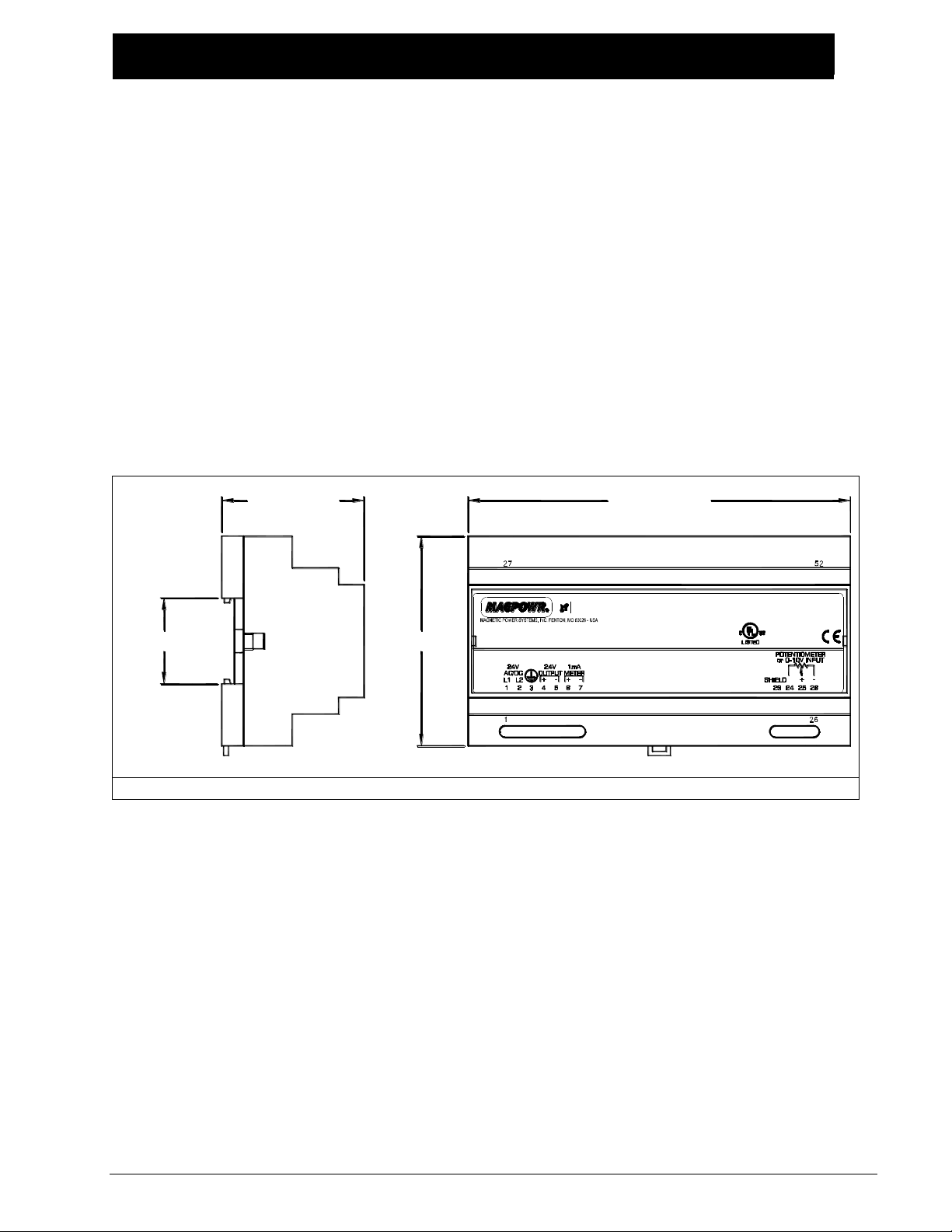
Enclosure ................................................................................................................. 3-1
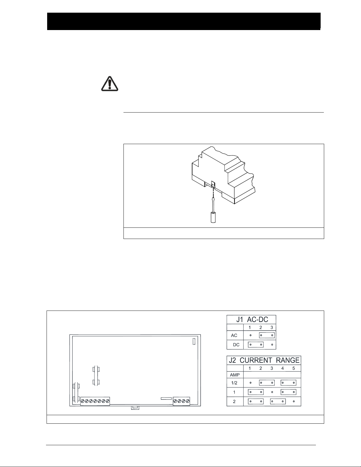
Power selection and current range settings ............................................................. 3-2
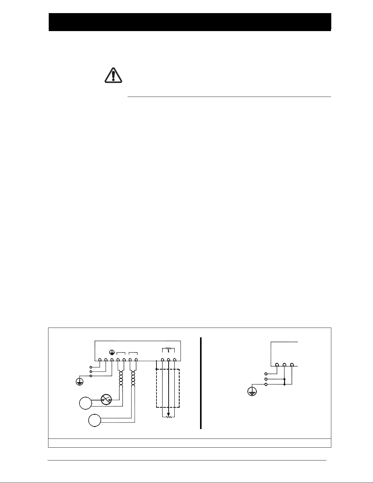
connections ............................................................................................................. 3-3
MAINTENANCE......................................................................................4-1
TROUBLESHOOTING ..............................................................................5-1
SPECIFICATIONS ....................................................................................6-1
SERVICE AND REPLACEMENT PARTS........................................................7-1

1–1
INTRODUCTION
www.maxcessintl.com MAGPOWR PS-24 Power Supply MI 850A302 1 D
About these
operating
instructions
All of the information herein is the exclusive proprietary
property of Maxcess International, and is disclosed with the
understanding that it will be retained in confidence and will
neither be duplicated nor copied in whole or in part nor be used
for any purpose other than for which disclosed.
Copyright 2004, all rights reserved.
Periodically there will be updates to this manual. The latest
version is available at
www.maxcessintl.com
or by calling
405.755.1600.
Language
These are the original instructions, written in English.

1–2
INTRODUCTION
www.maxcessintl.com MAGPOWR PS-24 Power Supply MI 850A302 1 D
Product overview
The MAGPOWR Model PS-24 is a controllable current regulator
for 24 VDC magnetic particle clutches and brakes. The PS-24
also provides a small amount of reverse current to maximize the
torque range of the clutch / brake.
The PS-24 may be powered from either 24 VAC or 24 VDC.
See Section 3-1.
The Model PS-24 has three jumper selectable current ranges.
Maximum outputs for the individual ranges are 0.5, 1.0 and 2.0
ADC. The appropriate range is determined by the current rating
of the clutch or brake to be controlled. For best torque control
resolution, the lowest current range providing sufficient current
for maximum operating torque should be selected. When using
24 VDC input power the maximum current output will be
slightly less than the selected range.
The PS-24 accepts either a remote adjustment potentiometer, or
a 0 to 10 VDC analog control signal. An isolation card is
required when the PS-24 is connected to an external non-
isolated control signal.
Connections are provided for an external 1 mADC current
meter. The meter display will indicate output current as a
percentage of the output range selected.
The control circuits are not electrically isolated from the power
circuits. The control circuit negative is connected to the P.E.
connection, that is, control input circuits are not floating.

2–1
SAFETY INSTRUCTIONS
www.maxcessintl.com MAGPOWR PS-24 Power Supply MI 850A302 1 D
Instructions for
use
To ensure safe and problem free installation of this product, it
must be properly transported and stored, professionally
installed, and placed in operation. Proper operation and
maintenance will ensure a long service life of the device. Only
persons who are acquainted with the installation,
commissioning, operation, and maintenance of the system and
who possess the necessary qualifications for their activities may
work on this product.
Note: The safety information may not be comprehensive.
Please note the following:
The content of these operating instructions
Any safety instructions on the device
The machine manufacturer’s specifications
All national, state, and local requirements for installation,
accident prevention and environmental protection
Safety symbols
Information about
safety instructions
The safety instructions and symbols described in this section
are used in these operating instructions. They are used to avoid
possible dangers for users and to prevent material damage.
SIGNAL WORD
Source of danger and its results
Avoiding dangers
The signal word DANGER refers to the danger of death or
serious bodily injuries.
The signal word WARNING refers to the danger of moderate to
severe bodily injuries.
The signal word CAUTION refers to the danger of slight to
moderate bodily injuries or material damage.
The signal word NOTICE refers to the possibility of damage to
equipment.

2–2
SAFETY INSTRUCTIONS
www.maxcessintl.com MAGPOWR PS-24 Power Supply MI 850A302 1 D
Symbols used
The following safety identification symbols are used in these
operating instructions.
WARNING/CAUTION –General danger or important note
Reference to general hazards that may result in bodily injuries
or damage to device or material.
WARNING/CAUTION –Danger due to voltage, electric shock
Reference to danger of injury caused by electric shock due to
voltage.
WARNING/CAUTION –Danger due to hot surfaces
Reference to risk of fire.

2–3
SAFETY INSTRUCTIONS
www.maxcessintl.com MAGPOWR PS-24 Power Supply MI 850A302 1 D
Basic safety
information
Proper use
The PS-24 is intended to power MAGPOWR brakes or clutches.
Indoor operation: see environmental specifications (Section 6-1).
Improper use
Operation outside the technical specifications
Operation in an Ex-area or intrinsically safe area
Operation as a safety component. The PS-24 does not supply
current to the clutch or brake if the power fails.
Outdoor operation
Any other use than the proper use shall be deemed inappropriate.
Installation and commissioning
Any PS-24 which is damaged must not be installed or put into
operation.
Only perform installation, maintenance or repair tasks on the
PS-24 when the machine has been stopped and is secured from
being turned on.
Only perform installation, maintenance or repair tasks on the PS-24
system when there is no electrical power in the system.
The PS-24 must be securely mounted before being placed in
operation.
Only replacement parts obtained from Fife may be used.
No modifications may be made to the PS-24.
Do not place electrical cables under mechanical strain.
WARNING –Death or injury can result from unexpected movement.
Protect against unexpected movement by removing electrical power
from PS-24 and the machine into which the it is being installed.
Maintenance and repair
WARNING –Death or injury can result from unexpected movement.
Protect against unexpected movement by removing electrical power
from the PS-24 system and the machine into which it is installed.
Decommissioning
The PS-24 must be disposed of in accordance with all the applicable
national, state and local regulations.

3–1
INSTALLATION
www.maxcessintl.com MAGPOWR PS-24 Power Supply MI 850A302 1 D
Installation
The PS-24 is intended for installation on a vertical panel with a DIN
35 rail, with the wiring terminals facing down. Figure 1 shows the
enclosure dimensions.
Wiring to and from the PS-24 must be done with double or
reinforced insulation or protective screening which provides
protective separation. All wiring should comply with the essential
requirements of the appropriate standard(s) and is the
responsibility of the installer.
Route input power away from control signal wiring. Connect shields
of shielded cable to the terminals indicated as “SHIELD”. Maximum
exposed shield length and maximum length of wires outside of the
shield is 75 mm [3.0 inches].
Figure 1. Enclosure dimensions
157.0 mm [6.18 in.]
35.2 mm [1.39 in] 85.9 mm [3.38 in.] M O D E L:
C LU T C H -B R AK E P O W E R S U PP LY
PS-24
C o m pa n y
Inte r na ti o nal
A M a xces s
58.4 mm [2.30 in.]

3–2
INSTALLATION
www.maxcessintl.com MAGPOWR PS-24 Power Supply MI 850A302 1 D
Power selections
and current range
settings
WARNING –Death or injury can result from unexpected movement.
Protect against unexpected movement by removing electrical
power from PS-24 and the equipment into which it is installed.
Remove the enclosure top by inserting a flat blade screwdriver
under the retaining tabs in the base (Figure 2).
Figure 2. Enclosure top removal
Set the J1 input voltage selection jumper to either AC or DC
depending on input voltage type. See Figure 3 for J1 input voltage
type setting. Set the current range selection jumpers to the range
appropriate for the clutch/brake connected to the PS-24 (See
Figure 3 for J2 current range settings). The factory setting is 1/2
amp range. Replace the enclosure top.
Figure 3. J1 input power selection / J2 current range settings
J1
J2

3–3
INSTALLATION
www.maxcessintl.com MAGPOWR PS-24 Power Supply MI 850A302 1 D
Electrical
connections
CAUTION –Never place electrical cables under mechanical strain.
Always provide mechanical support of wiring with either clamps
or flexible or rigid conduit.
There are three connections (Figure 4) required for the basic
system:
24 VAC/VDC power
24 VDC output for clutch / brake
1 kΩto 10 kΩpotentiometer
Route input power away from control wiring. The clutch/brake
wires and the remote meter wires should be twisted pair. Run the
signal input wiring in shielded cable. Connect the shield to the
provided terminal marked “SHIELD”. The maximum shield length
and maximum length of wires outside of the shield is 75 mm
[3.0 inches].
When using a 0 to10 VDC input instead of a potentiometer,
connect the negative of the input to terminal 26 and the positive
of the input to terminal 25. The 0 to 10 VDC signal should be
isolated from PE. If not isolated from PE, EMC performance may be
degraded.
The 0 to 1 mADC output and the potentiometer input negative
lead is ground referenced.
The 24 VDC output must be floating with respect to ground.
When using multiple PS-24 units, each one must have its own
power supply.
Alternate wiring for non-isolated
24 VDC supply. EMC performance may be
degraded. Do not use with AC supply.
Figure 4. Electrical connections for PS-24
REMOTE POTENTIOMETER
1K TO 10K
L1 OUTPUT METER
L2 + -
24V 1mA
POTENTIOMETER
or 0-10V INPUT
SHIELD + -
1 2 3 4 5 6 7 23
AC/DC
24V
CW
-+ 24 25 26
ALLOWED IN
(OPTIONAL)
CLUTCH/
BRAKE
METER
REMOTE
0-1 mA DC
D.C. OUTPUT
24 VAC, 50/60 Hz
or
SWITCH NOT
24 VDC
ISOLATED
ONLY
1 32
24 VDC

4–1
MAINTENANCE
www.maxcessintl.com MAGPOWR PS-24 Power Supply MI 850A302 1 D
Maintenance
To reduce the risk of fire, replace only with the same type fuses as
specified in Section 6-1.
WARNING –Death or injury can result from unexpected movement.
Protect against unexpected movement by removing electrical
power from PS-24 and the equipment into which it is installed.
The only maintenance that may be required on the PS-24 is fuse
replacement. Replacement of the fuse(s) requires first removing
input power, and then opening the enclosure.
The enclosure may be opened by inserting a flat blade screwdriver
under the retaining tabs in the base (See Figure 2).
The enclosure must be re-installed to maintain the IP rating.

5–1
TROUBLESHOOTING
www.maxcessintl.com MAGPOWR PS-24 Power Supply MI 850A302 1 D
Troubleshooting
Symptom
Possible Cause
Solution or Diagnostic
No clutch/brake output
No input power
Verify incoming power is correct
voltage and frequency.
J1 selection wrong
Verify that J1 is set to AC or DC to
match the type of power input.
Fuses blown
Clutch/brake wires shorted together or
shorted to ground.
Clutch / brake wires
open circuit
Disconnect clutch/brake wires at the
PS-24 and check for proper
clutch / brake resistance between the
wires.
Remote potentiometer
or external power
supply not wired
correctly, or shorted
together
Voltage between terminal 24 and 26
should be 10 VDC.
Voltage between terminal 25 and 26
should vary from 0 to 10 VDC as the
potentiometer or external 0 to10 VDC
power supply is moved through its
range of travel.
Remote meter not
working
Incorrect type of meter
Meter should be a current meter with
1 mADC full scale and no more than
100 ohm resistance.
Meter wires shorted or
open
Disconnect meter wiring at the PS-24
and check for proper meter resistance
between the wires.

6–1
SPECIFICATIONS
www.maxcessintl.com MAGPOWR PS-24 Power Supply MI 850A302 1 D
Specifications
Supply voltage
24 VDC, 2.1 amp maximum, 49 VA with clutch or brake coil
24 VAC, ±10%, 50/60 Hz, 2.1 amp maximum, sinusoidal,
49 VA with clutch or brake coil
Fuses:
F1
2.5 amp
Littelfuse Part No. 21602.5 or
Wickmann Part No. 19194-058-FS
F2
5.0 amp
Littelfuse Part No. 216005 or
WIckmann Part No. 19194-063-FS
Enclosure:
IP20
Climatic class:
3K3 (EN60721)
Temperature range
Operating:
0º C to 50º C
Storage:
-30º C to 80º C
Relative humidity:
5% to 85%
Pollution degree:
2 (IEC664-1)
Altitude:
0 to 2000 m
Compatible residual
current device types:
A or B (IEC755)
Worst case fault current:
2.5 amp
Inputs
Signal:
Potentiometer: 1 kΩ to 10 kΩ, ¼ watt minimum, or
Voltage: 0 to 10 VDC, 100 kohm input impedance
Outputs
Clutch/brake
Voltage:
-1.2 to 24 VDC, duty cycle/phase controlled
Current:
Adjustable in three ranges:
-0.016 to 0.5 ADC
-0.032 to 1.0 ADC
-0.064 to 2.0 ADC
Regulation:
<1% of range
Current drift:
0.024%
Meter signal:
0 to 1 mADC, ±3% into 100 ohm maximum
Potentiometer:
10 VDC ±3%, 10 mADC maximum

7–1
SERVICE
Service requests
and replacement
parts
To request service or to get replacement parts, contact
Maxcess:
Maxcess Oklahoma
222 West Memorial Rd.
Oklahoma City, OK, 73114, USA
Phone: 1.405.755.1600
Fax: 1.405.755.8425
Web: www.maxcessintl.com
When ordering replacement parts, please indicate, where
possible, part number, drawing number and model description.
If it is necessary to return this product for service, care must be
taken to properly package the unit to prevent damage during
shipment. If possible, use the original shpping containers.
AMERICAS
Tel +1.405.755.1600
Fax +1.405.755.8425
sales@maxcessintl.com
www.maxcessintl.com
EUROPE, MIDDLE EAST
AND AFRICA
Tel +49.6195.7002.0
Fax +49.6195.7002.933
www.maxcess.eu
INDIA
Tel +91.22.27602633
Fax +91.22.27602634
india@maxcessintl.com
www.maxcess.in
JAPAN
Tel +81.43.421.1622
Fax +81.43.421.2895
japan@maxcessintl.com
www.maxcess.jp
KOREA, TAIWAN,
AND SE ASIA
asia@maxcessintl.com
www.maxcess.asia
© 2018 Maxcess
Table of contents
Other Maxcess Power Supply manuals