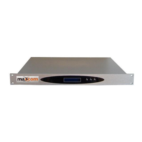
Maxcom MX1000R Series User manual

M
MX
X1
10
00
00
0R
R
S
Se
er
ri
ie
es
s
A
AG
GC
C
F
Fo
or
rw
wa
ar
rd
d
P
Pa
at
th
h
O
Op
pt
ti
ic
ca
al
l
R
Re
ec
ce
ei
iv
ve
er
r
G
Ge
en
ne
er
ra
al
l
U
Us
se
er
r
M
Ma
an
nu
ua
al
l-
-S
Sp
pe
ec
c
S
Sh
he
ee
et
t
PRODUCT DESCRIPTION
The MX1000R2 and MX1000-36 CATV Fiber Optic receivers are designed for high reliability with
optical AGC, high level RF output, ease of use, easy to read LED indicators, and is suitable for
high-level applications.
FEATURES AND BENEFITS
•Optical AGC
•Wide adjustable Output level and slope range
•Operating parameters controlled by microprocessor and indicated on display screen
•Dual power supply provides for full-automatic backup switching
•Chassis temperature is auto controlled
•Advanced Network Management functions
•Intuitional RF output level display
•*Optional Dual Input Switch with Auto Detect for Redundancy

PRODUCT SUMMARY
The MX1000R is a one way forward path optical receiver.
Users may adjust RF output level, slope, and RF operating mode through the front panel controls.
Users may also monitor the devices operating status through the LCD screen or with optional
SNMP.
RECEIVER CONTROLS, INDICATORS, AND ALARMS
This section of the manual will give an overview of the available menus in the MX1000R series
optic receiver and their descriptions. All instructions refer to the representation of the front panel
shown in the diagram below. The user scrolls through the menus using the push button found on
the front panel.
Operation of the panel
1.1.1 Open menu
A. Plug into AC110V power supply or -48 VDC
B. Turn on power switch on the rear panel (AC versions)
Receiver enters a self-diagnostic mode, after checking it begins operating status, and
will display “Forward optic receiver”.
RX1 Status lamp Red (input optical alarm)
RX2 Status lamp Red (backup input optic alarm) (MX1000R lamp is
not illuminated) (*2nd input optional)
ALARM Status lamp Green (RF output alarm)
POWER1 Status lamp Green (power 1 alarm)
POWER2 Status lamp Green (power 2 alarm)

1.1.2 Start-up main menu
Press “any button”button to display below menu in sequence.
MODEL
Read-only menu, indicates the model of this device
S/N
Read-only menu, indicates the serial-number
INPUT1
Read-only menu, indicates the input optical power
INPUT2 (if equipped with dual input option)
Read-only menu, indicates the input optical power
RF MODE AGC
Adjustable list, display the operating mode, user may change the operating
mode of the first stage RF attenuator to AGC (optic automatic gain control) or
MGC (Manual gain control mode) by this menu. Suggest using AGC mode.
MGC
Adjustable list, only active when RF MODE is set to MGC
ATT/RF Adjust
Adjustable list, display the output level (second stage attenuation), each single
step is 1dB
SLOPE ADJ
Adjustable list, display the slope of output signal, each single step is 1dB
Channel NUMBER
Adjustable list, display the number of channels of transmitted signal, the default
is 59, this menu is used for calibrating level display
RF IN 1
Read-only menu, indicates the input signal’s level
RF IN 2 (if equipped)
Read-only menu, indicates the input signal’s level
RF OUT
Read-only menu, indicates the output signal’s level internally
POWER1
Read-only menu, indicates the voltage of hot plug power supply 1 is +24V

POWER2
Read-only menu, indicates the voltage of hot plug power supply 2 is +24V
LCD Contrast Control
Adjustable list, displays the LCD contrast level adjustments
Menu Options if unit has SNMP Option:
IP
Adjustable list, displays the IP address of SNMP
Subnet
Adjustable list, displays the address of sub-net mask
Gateway
Adjustable list, displays the getaway address
Trap1
Adjustable list, displays the trap1 address
Trap2
Adjustable list, displays the trap1 address
1.1.3 Menu assistant manual
Press “UP”or “DOWN”button to select the menu that you wish to modify, press
“RIGHT”button to enter modify status, then press “RIGHT”or “LEFT”button to shift
the key to the position that needs to modified, press the “UP”or “DOWN”button to
change the value, after making change, press the “RIGHT”button to save. Press
“LEFT”button to exit or cancel this setting.
Ex: modify IP: 192.168.000.015, If you need change the 5 to 6, press “DOWN”
button to select IP menu, press “RIGHT”button to enter modify status, then press
“RIGHT”button to shift the key to 5 this position, and then press “UP”or “DOWN”
button amend current value, press “RIGHT”button to shift right to save and exit.
Press “LEFT”button to shift left to cancel and exit.

RS232 USER INSTRUCTIONS
Connect the device to a PC by using an RJ45 data cable, use your PC’s serial port assistant software to see the
working parameter of this device
Control command: READ
Baud rate: 9600
Data bit: 8
Stop bit: 1
Check bit: NONE
Control flow: NONE
NOTES
1. Input optical Power: For optimal performance, the received power should be between -7~+2 dBm. Receiver will
operate as low as -12 dBm Input power, however CNR will deteriorate as input power decreases. If input power is too
high, it will cause CTB and CSO deterioration. When received power is >3dBm (2mW), it may potentially damage the
optical receiver module.
2. RF output level: optical receiver’s RF output level is related to receive power and optical receiver’s RF drive level
(the modulation coefficient). Typically, as receive power increases or decreases by 1 dB, optical receiver’s RF output
level would increase or decrease 2 dB (1:2). If the Optical receiver’s RF drive level increases or decreases 1 dB, the
optical receiver’s RF output level would increase or decrease 1 dB (1:1).
3. CTB and CSO: RF output level too high will cause the CTB and CSO index to deteriorate. Shall output level
increase 1dB, and CTB would deteriorate 2dB, CSO would deteriorate 1.5dB. When adjusting optical receiver’s RF
output level, you should ensure the distortion index CTB≤-65dB, CSO≤-60dB.
ERROR AND REMEDY
No RF output
Check the power supply of the unit to determine whether it is normal.
Insert optical connector, if the RX-Low is showing a red light, or no optical power, you should use an optical
power meter to measure the optical power of the optical cable output connector. If optical power is normal, it
may not be seated well into the optical connector, (this unit adopts SC/APC), or optical receiver module may be
damaged, if damage is suspected, you should contact Maxcom and return for factory maintenance.
RF output level too low(<20dBmV)
Check received optical power to determine if too low. (<-12dBm)
RF output level too high causing the distortion index to be deteriorated
Check received optical power to determine if too high, such as >3dBm you should install an optical attenuator.
Check the head-end optical receiver’s RF drive level whether too high. Optical receiver’s RF drive level
determines the modulation, it also determines the system index (CNR, CTB, CSO). Designing should meet
optical receiver manufacture requirement.
If received optical power and optical receiver RF drive level are all normal, optical receiver RF output power
may be adjusted through ATT1.

Performance
MX1000R2 and MX1000-36
Optical feature
Wavelength (λ)
(nm)
Agnostic 1290-1630, Typical 1310/1550
Input power
(dBm)
-12~+2
Operating mode
Optical AGC (when using the MGC function, AGC will not
be operational)
Return wave loss
(dB)
≥55
Optical connector
SC/APC
RF feature
Bandwidth
(MHz)
45~1000
Output level
(dBmV)
MX1000R2=53dBmV / MX1000R-36=36dBmV
Flatness
(dB)
≤±0.5
Output level adjustable
(dB)
0~20MGC (ADJ)
Output level adjustable
(dB)
0~20(ATT)
Output slope adjustable
(dB)
0~15(SLOPE)
Return loss
(dB)
≥16(750MHz)
Output impedance
(Ω)
75
Link feature
Test channel
ATSC-D/79CH
CNR
(dB)
≥52(10Km fiber,-1dBm receive)
CTB
(dB)
≤-70
CSO
(dB)
≤-63
General feature
Network management
interface option
RJ45, R232(supports IE & SNMP)
Power supply
(V)
110VAC (-48VDC option)
Power consumption
(W)
≤50 (single PS operation)
Work temp.
(*F)
-23~149 (Unit temp. controlled automatically)
Storage temp.
(*F)
-40~185
Relative humidity
(%)
5~95
Size (W)x(D)x(H)
(inch)
14.5×17.25×1.75
877-330-5333
www.maxcomcorp.com
This manual suits for next models
2
Table of contents
Other Maxcom Receiver manuals
Popular Receiver manuals by other brands
SCHNERZINGER
SCHNERZINGER GIGA PROTECTOR quick start guide

SHENZHEN FLYING INDUSTRY DEVELOPMENT
SHENZHEN FLYING INDUSTRY DEVELOPMENT S1PUW-AC-ANT3 manual
Knoll
Knoll IR250 installation instructions
Denon
Denon AVR 3802 Service manual

Panasonic
Panasonic RF-2400D owner's manual

Hanwha Techwin
Hanwha Techwin SBP-329HM quick start guide
