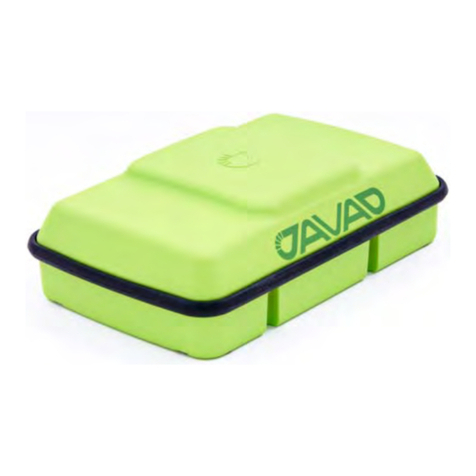
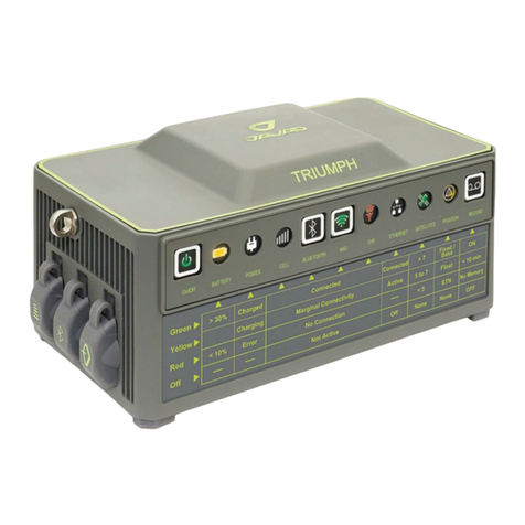
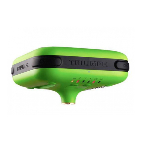
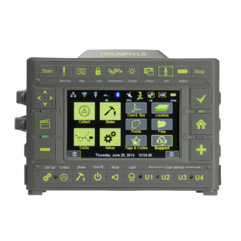
Javad TRIUMPH-LS User manual

USERS GUIDE TO THE TRIUMPH-LS
E
Version 20160121

www.javad.com
2Table of Contents
Table of Contents.............................................................................2
Introduction............................................................................... 4
What’s in the box? ...........................................................................4
Conventions.......................................................................................5
Charging the TRIUMPHLS ..........................................................6
Monitoring the TRIUMPHLS ......................................................6
Data Storage......................................................................................7
Mobile Telecommunications ......................................................7
WARNINGS! ........................................................................................8
Sun screens........................................................................................8
Attaching an external UHF antenna .........................................9
Timing............................................................................................... 10
User Dened Buttons.................................................................. 10
Interference .................................................................................... 11
Print Screen..................................................................................... 12
Locks.................................................................................................. 13
Mute .................................................................................................. 13
Record Voice................................................................................... 13
Calculator......................................................................................... 14
Flashlight ......................................................................................... 14
Language......................................................................................... 14
Calendar........................................................................................... 15
Camera ............................................................................................. 15
GNSS Interference ........................................................................ 16
Field Set Up .............................................................................. 18
Setting Up the Radio ................................................................... 18
Setting Up the RTK Base............................................................. 21
Antenna Heights........................................................................... 21
Internal Antenna Osets............................................................ 22
Set Up the RTK Rover................................................................... 23
Connect With 3G ...................................................................... 25
SIM Card Conguration .............................................................. 25
Collect....................................................................................... 28
Stake Out ................................................................................. 40
Stake Out Points............................................................................ 41
GUIDE Command:......................................................................... 47
Staking Lines and Arcs................................................................ 51
Stake Out Alignments ............................................................. 60
Tutorial — Creating an Alignment......................................... 62
Creating Horizontal Alignment ............................................... 63
Creating Vertical Alignment...................................................... 71
Dening Cross-Sections ............................................................. 76
Entering Oset Points................................................................. 79
Modifying the Alignment .......................................................... 80
Staking.............................................................................................. 81
Stake Settings ................................................................................ 81
Stake Modes ................................................................................... 87
Using ShapeTags and Codes ................................................... 92
Data Structure................................................................................ 93
Dening ShapeTags & Codes.................................................... 94
Favorite ShapeTags & Codes..................................................... 94
Using ShapeTags........................................................................... 95
Of ShapeTags and Codes .........................................................102
Coordinate Systems...............................................................106
Coordinate System Basics........................................................106
Building Coordinate Systems .................................................108
Unknown Coordinate Systems ..............................................111
Inuences in CoGo .....................................................................113
Surfaces..........................................................................................117
Using CoGo Function............................................................. 118
Localization............................................................................126
Single Point Localization (Known)........................................126
Multiple Point Localization (Known)....................................135
Single Point Localization (Unknown) ..................................138
Multiple Point Localization (Unknown) ..............................143
Terms and Concepts ..............................................................150
Project.............................................................................................150
Page.................................................................................................150
ShapeTags ....................................................................................151
Codes ..............................................................................................151
RTK Positioning and Verication ...........................................151
Ellipsoids .......................................................................................152
Geoids ............................................................................................152
Transformations .........................................................................152
Projections ...................................................................................153
Localization ..................................................................................153
Auto Naming and Sequencing .............................................153
Collect and Stake .......................................................................153
Setup, Proles and Projects ....................................................153
Compass and Levels .................................................................154
Trouble Shooting................................................................... 155
Forced Update .............................................................................156
Table of Contents

www.javad.com
3
Table of Contents
Specications.........................................................................157
Ancillaries............................................................................... 159
TRIUMPH-2 + Charging Kit......................................................159
12v Battery + Charging Kit ......................................................160
HPT401BT + Charging Kit ........................................................161
Accessories............................................................................. 162
Appendices ............................................................................163
Appendix A - Blinking LEDs ....................................................163
Appendix B - NGS AntCal Data ..............................................165

www.javad.com
4Introduction
Introduction
Congratulations and thank you
for purchasing the TRIUMPH
LS, the next generation and
revolutionary innovation in high
precision GNSS surveying from
Javad GNSS. The TRIUMPHLS
contains the most advanced
set of GNSS hardware and
engineered technologies with the TRIUMPH 2 chip at the
heart of it all. Refer to this USERS GUIDE while familiarizing
yourself with the TRIUMPHLS and be sure to check for
digital updates to this document on the website.
What’s in the box?
Item Check List
Before starting, check that all of
the following items have been
included with your TRIUMPHLS.
If anything is missing, contact
your dealer as soon as possible.
Depending on the options that you’ve previously congured
with your purchase, your RTK kit may contain either one, or
the other of the two antennas listed here:
UHF antenna 400-470 MHz, 2.5dB, RT Angle, SMA
(optional, if UHF module is
installed)
SMA-TNC Adapter
USB Cable, A/microB
1/4” to 5/8” Adapter
AC Power CableExt Power/Charger
Power Cable AC Power Adapter*
* Plug shown is for USA
Charging kit
(shown assembled)
8GB microSD
(w/ adapter)
Tweezers
TRIUMPHLS
Antenna 868-928 MHz, 5dBi, Swivel, SMA (optional, if
FH915 module is installed)
OR

WARNINGS!
!
www.javad.com
5
Introduction
Conventions
This manual uses the following icons, symbols and styles:
Sidebar notations
Cautionary alerts to prevent damage
to equipment or loss of data
Supplemental information
www.javad.com Indicates an active link in the PDF
The Quick Start Guide to the TRIUMPHLS should be
read and studied before reading this User Guide to the
TRIUMPHLS. This manual is intended to cover topics not
covered in the Quick Start Guide to the TRIUMPHLS.
This manual is also being rapidly released for new and
existing RTK surveyors that have purchased the TRIUMPH
LS eager to get up to speed and at work in the eld.
Accordingly, it is being released in stages of development
as new features get added and others further rened.
More detailed information on many subjects pertaining to
the use of the TRIUMPHLS can be found in the back of this
guide including trouble shooting and where to nd help.
Localization
(p. 126)Active Cross-reference link in the PDF
See (p. 5) TCP Client Branched reference

www.javad.com
6Introduction
Battery
Pack-1
Battery
Pack-2
When the TRIUMPHLS is powered o and is being charged,
the top (2) LEDs indicate the state of the (2) charged battery
packs and the bottom (2) LEDs indicate the rate of charge. If
the bottom LEDs are blinking yellow or red, it indicates that
temperatures are over 40° C and that charging will resume once
cooled. A complete charge takes about 5 hours when LS is cool.
External voltage; when connected
Internal delivered voltage to all modules
Power consumption - Watts
Battery Pack-1 voltage
Battery Pack-2 voltage
Battery Pack-1 discharge - Ampere
Battery Pack-2 discharge - Ampere
Estimated remaining battery power or
charging icon
Communications module temperature - ° C
Battery Pack-1 temperature - ° C
Battery Pack-2 temperature - ° C
GNSS module temperature 2 - ° C
Tap on numerical boxes to show / hide graphs
Check for Instantaneous, Minimum, Maximum and Average graphs
BATTERY STATS
Charging the TRIUMPH-LS
When the TRIUMPHLS is turned o and charging, the four
LEDs will keep you apprised of its charging progress for
both of the individual battery packs as illustrated below.
As noted and shown below, all (4) green LEDs rst appear
at 90%. Interrupting the charging and then resuming will
have no eect until the discharged state is less than 8 volts.
To reach maximum charge, allow an additional 20 minutes
once all green is seen.
Monitoring the Temperatures and
Batteries
When the TRIUMPHLS is turned on and
not charging, the upper right and lower
left LEDs give you a quick indication as to
the status of the two battery packs. For
more detailed information regarding the
status of the two battery packs as well as
other internal conditions and behaviors during the previous
30 hours, tap on the battery icon or press the Battery
hardware key.
OS module temperature - ° C
GNSS module temperature 1 - ° C
Charged state: almost empty
Rate of charge: full speed
Charged state: half charged
Rate of charge: full speed
Charged state: half charged
half speed : Rate : full speed
Half speed used to help get temp under 40° C
Charged state: fully charged
Rate of charge: stopped
Green light will rst appear at about 90% complete
Power and temps for the last 30 hours

www.javad.com
7
Introduction
Align the card exactly as it is
shown on the rubber port cover
Insert the card with the leading
edge exactly as shown on the
rubber port cover
Fully insert the card into the
recess
These are Push-Push style card
slots; to remove the card, fully
insert the card again
microSD Card Installation SIM
Use the provided high-speed microSD
card. Replace with Class 10 or better
While handling, take care not to damage
the circuitry printed on the underside of
the card
Use the provided tweezers to
install and remove these tiny
devices and to help mitigate
oily ngerprints on the contacts
Data Storage
In addition to the internal solid state data storage on
the TRIUMPHLS, you will also want to use the provided
microSD card as a backup for your eld data. Updates to the
system will automatically use the microSD card as a backup
if present.
Mobile Telecommunications
If you work in areas with good cell coverage that also
happen to have Real Time Network (RTN) services from
area base stations, you may wish to purchase a data plan
through your local telecommunications provider. Take care
to properly orient the SIM card as it will only work when it’s
been oriented as shown below.

www.javad.com
8Introduction
WARNINGS!
Some warnings that are displayed may
be expected; for example, in the oce
with the TRIUMPHLS powered on and
near your computer you may receive a
warning about
High Interference!, or when you
rst receive your instrument,
there may be a warning that
level and compass calibrations
are necessary. Pay attention to the messages, even if they’re
expected. Did moving the receiver away from the computer
eliminate the High Interference! warning?
The TRIUMPHLS is a remarkably sensitive instrument to
your invisible environment and can help you stay alert to
problems as soon as they arise. Listen to it.
Sun screens
Sun screens were developed to improve
screen visibility when in very strong direct
sunlight. These alternative high contrast
screens are available anytime with a push
of a button.
Not every screen has three alter-
nate contrast settings though you’ll
still need to cycle through them
three times to return to the rst
screen setting. The Home screen is
such an example.
Sun Screen3Sun Screen2Sun Screen1

www.javad.com
9
Introduction
reception of your base station’s corrections by the rover
can be enhanced using an external UHF antenna. Begin by
attaching the external antenna. In this image, we see the
2.5 dB gain antenna attached to the TRIUMPHLS.
For the purposes of this discussion it is assumed that you
have already attached the external UHF antenna, are in
the eld, the LS is powered on, that it’s setup as the RTK
rover, the RTK base is on and the UHF radio is broadcasting
corrections.
Even when the external UHF antenna is attached, the default
internal UHF antenna will be used until you congure the LS
to behave otherwise. From the Home screen tap on the UHF
icon to bring up the UHF status screen. Notice the Received
Signal Strength Indicator’s (RSSI) value before proceeding
to tap Conguration, select External Antenna and tap OK.
Anytime the UHF communications are interrupted; such as
in this example, it will take a few seconds up to a minute or
so for them to be reestablished.
Attaching an External
Radio Antenna
When purchased with an internal UHF or FH915
radio, the TRIUMPHLS comes with an external
radio antenna.
Maintaining a Link
Quality (LQ) at or near
100% is crucial for
good performance
with the RTK system.
When doing RTK
surveying, the
The Correction Status button shown in the Stake and Collect
Action screens. When green, corrections are being received.
The bars above the icon graphically represent the RSSI while
the link quality is displayed below the icon. Tap to open the
UHF Status screen.
The UHF Status Screen
The UHF Conguration Screen

www.javad.com
10 Introduction
Timing
Tap on this icon to bring up
the dialog for setting how
time gets displayed in J-Field.
Alternatively, you can bring
up these settings by tapping
on the date and time that is displayed at the bottom of the
Home screens.
Time display is
an example of a
global setting. The
default global
setting is UTC,
but once you’ve
tapped on the
Local Time Zone
eld, set it to your
local time; e.g., UTC-4 for Eastern Daylight, J-Field will recall
that setting regardless of your Setup or Project.
Aside from knowing at a glance what time of day it is,
many les that J-Field writes are time-stamped including
screenshots, photos, and audio les which can be very
helpful during the job and well afterwards.
You can also schedule audible alarms for yourself, but don’t
forget to turn the sounds back on if you’ve set the volume
on mute.
It is also possible to schedule your survey to begin at a xed
moment in time; for example, this would be handy if you’re
coordinating multiple static sessions across a large area and
wanted them to all begin collecting data at the same time.
User Dened Buttons
The U1 through U4 User Dened Buttons can be assigned
from Setup with the Assign U1-U4 button:
Assign Action U1 Screen - Available Options

www.javad.com
11
Introduction
Interference
There are two separate
spectrum analyzers in the
TRIUMPHLS. The following
brief discussion will focus
on the analyzer that scans
all GNSS bands. The other scanner that will be discussed
elsewhere in this manual deals with UHF bands.
We live in an increasingly noisy environment and without
special equipment, this type of noise; electromagnetic
interference, can largely go undetected - even when you’re
getting xed positions! The sophisticated hardware and
software contained in your TRIUMPHLS is not only capable
of detecting, documenting and reporting the interfering
signals across all of the GNSS bands, it is designed to mitigate
their debilitating eects up to about 20 dB in strength. If
the interference is too high, however, no mitigation eort
can improve the receiver’s performance when in such noisy
places.
For the most part, the surveyor need not worry about
interference with satellite signals as the TRIUMPHLS is
doing its duty for you, but there may be instances when
your results begin falling beyond normal
expectations. Being able to identify
those physical locations as well as the
magnitude of such interferences will aid
tremendously in your evaluation of the
quality of the data that you’re collecting
and the health of the receiver. When

www.javad.com
12 Introduction
such data is collected across large regions from many
users, it could go a long way towards ensuring a cleaner
environment and the safeguarding of our GNSS bands.
To lter its own harmonics which are generated from internal
circuitries, individually each TRIUMPHLS’sInternal GNSS
antenna is calibrated inside a very quiet place; an anechoic
chamber. The unique calibration prole for your receiver is
also stored on the Javad GNSS server as backup. Should you
ever need to, your receiver’s internal antenna calibration
prole can be restored using an Internet connection.
Print Screen
Screen captures are easily facilitated
with press of a single key devoted to this
purpose allowing you to conveniently
document your activity whenever you
want. These screen captures provide and
preserve a wealth of information for later reference and for
sharing with others.
To enable easy retrieval, J-Field helps you keep track of
screen shots by rst, a clear naming policy. Each screen’s
3-character prex is the name of the receiver followed by
the name of that screen and nally the sux is its date
stamp.
File storage is also handled very logically with screenshot
images stored under the parent folder; ScreenShots and
then grouped by day.
Bumpy blue line is an example of interference found on GPS L5
and which the TRIUMPHLS has mitigated
Black line shows the spectrum scan of the frequency of GPS L5
Blue line shows the voltage required to mitigate interference

www.javad.com
13
Introduction
Record Voice
Save time in the eld
describing the feature with
the voice recorder with just
a tap from Home screen.
Alternatively, instruct J-Field
to automatically begin recording immediately with each
location or just on select selected occasions from one of the
many user congured white boxes on the Action screen.
You can immediately play back the audio notes with a
couple of taps. From Home screen, Files, then if collected
with points at the same time, tap the top row Audio Files to
pick. You may want to mute your TRIUMPHLS if you turn
on auto record.
Mute
The TRIUMPHLS makes various sounds
all intended to keep you apprised as to
the status of many dierent things and to
help you interact with it.
There may be occasions when the noises are unwanted for
example, long unattended static sessions or when making
an audio note to self.
One thing to be mindful of is the relationship of the Mute
setting (on or o) with a given General Group prole. In
other words, the Mute button is not a global setting. It is
specic to that particular prole and can be accordingly
recalled anytime that the prole gets recalled.
Locks
Prevent inadvertent taps and
key presses use this feature
to dene when and how they
get locked.

www.javad.com
14 Introduction
Flashlight
The TRIUMPHLS has a fantastic
built-in LED ashlight on its
bottom surface.
Press the Light
key any time that
the TRIUMPHLS
is turned on in
operation.
Note that the ashlight will only
work when J-Field is up and
running.
Language
The TRIUMPHLS has largely
been developed for English
speaking surveyors; however,
plans call for J-Field to be
translated into other languages.
Calculator
Access J-Field‘s Calculator from
Home screen featuring trig and
log functions. The calculator
also is able to quickly calculate
the perimeter and area for two
simple gures, a circle and a triangle. The triangle routine
has the user enter lengths of three sides. Circumference and
area of circles are determined by the user’s entry of a radius
value.
The operands and results can both be seen in the top row of
yellow boxes. Tapping on one of them will allow its value to
be stored in memory.

www.javad.com
15
Introduction
Calendar
Project les on the TRIUMPH
LS are represented in a
chronological overview using
a scrollable calendar.
You may elect to utilize the default Project naming schema
out of ease of use and convenience and then later, rename
it to your specic job ling system. Other aspects of the
project can be examined once you’ve chosen and opened
an existing project.
Camera
To activate either camera;
forward or downward, tap
on this icon found on Home
screen to take photographs
using one of the two cameras
found on the TRIUMPHLS. Alternatively, you can congure
one of the User Dened Boxes available for the user’s
convenience on the Stake or Collect Action screens or via a
user dened key; e.g., U1.
Downward facing camera is near the
edge closest to the display screen
Forward facing camera is near the
bottom edge between the SIM ports
File storage is handled logically with images stored under
the parent folder; photos and then grouped by day.

www.javad.com
16 Introduction
GNSS Interference
The D-SNR screen which tells you at a glance the general
status of satellite signals in the (4) GNSS Bands used in RTK
solutions
Blue shows nominal GNSS signal strength interference less
than -3 db of the expected signal strength. In this example,
the setting was in a fairly open urban area with mostly open
sky above but with buildings, trees and overhead utilities
within the surrounding immediate area.
Green values indicate an area with interference greater
than -3 db up to -6 db.
Red values indicate an area with interference greater than
-6 db and though this interference level is high and will
often be accompanied with the warning LED being lit. Its
still possible that you may be able to obtain positions in
such dicult environments; however, you’ll likely need to
remain in that location for longer periods of time.

www.javad.com
17
Introduction

www.javad.com
18 Introduction
Find your control point
Before you set up your radio,
nd your existing control or
decide where your control
station will be. For this
discussion, it is presumed
that you have previously
done your recon, have found
the optimal location for your
RTK Base; i.e., as much sky
as possible, as your base’s
corrections will otherwise
be curtailed if it’s unable to receive signals from the same
Space Vehicles (SVs)that your RTK Rover is able receive.
Ideally, your base should be able to see all healthy SVs.
Set up your radio
Knowing where your RTK base is going to be set up to
maximize satellite reception is the rst step in setting up
your radio.
Other criteria for your radio’s location will be predicated
on 1) mitigating the electromagnetic eects of the radio’s
transmissions on the GNSS receiver, 2) the practicable range
of the Bluetooth connection between the RTK base and
the radio and lastly 3) the higher the antenna, the further
the line of sight distances will be allowed which is one
element eecting the range of the rover while still receiving
corrections.
Field Setup
Setting Up the UHF Radio

www.javad.com
19
Introduction
With regard to the rst item, I asked Javad how close is too
close when it comes to setting up the radio and here is his
response:
Hello Kelly,
There is no hard rule. The eect depends on the power of
the transmitter. Vertical or horizontal separation is the
same. The further you are the eect is less. For 1 watt
stay away a few feet. For 45 watt, stay away 20 feet. The
further the better.
Regards,
Javad
In regards to the second point, I asked Vladimir Zhukov
this question: “What is the most practicable range of the
communication between the T2 and the HPT404BT (shown in
this example) aorded through Bluetooth ? “ and his answer:
Hi Kelly,
Up to 50 ft (~15 m) is the practicable range of the
communication between TRIUMPH-2 and HPT401BT/
HPT404BT.
Actually in the eld they keep reliable connection up to
130 ft (~40 m).
So, > 130 ft is too far.
Regards,
Vlad
The last bit, the height or elevation of the antenna has
two things relevant for you to consider; 1) power and 2)
viewshed. If you have the base RTK kit that comes with (2)
6’ SAE extension cords and the battery kit power cable , this
comfortably adds another 5’ or so plus the 1’ pigtail. That’s
about a maximum of 18’ between the 12-volt battery and
the radio that’s permissible.
The viewshed may take some study beforehand. An
excellent program that may already be in the surveyor’s tool
kit (or should be) is Global Mapper which allows the user
to easily determine line of sight from your DTM, LiDAR, or
other elevation data; viewshed even has its own icon! (See
Appendix D for an example).
Finally, if you don’t have an FCC license for your radio,
you really need to read Mark Silver’s excellent article
that appeared in the January 2014 issue of The American
Surveyor: “Sailing with the Pirate Surveyors,” which you can
read here: http://www.amerisurv.com/PDF/TheAmericanSurveyor_
Silver-PirateSurveyors_Jan2014.pdf
Once the radio is all setup - and make sure the antenna is
connected to the radio - turn on the radio by plugging it
into the battery cable if you’re using the HPT404BT or press
the power button on the radio if you’re using the HPT401BT.
Refer to Appendix A (p. 163) for an explanation of the blinking
LED lights on the radio.

www.javad.com
20 Introduction
If there is no data for transmission, for example when
charging the HPT401BT’s attached battery, the antenna
need not be on the HPT401BT; however, if the TRIUMPH2
was on and nearby, its Bluetooth connection will continue
to send transmission of corrections, so it’s safest to keep the
antenna connected to the radio.
Shown in the photo on the left, is the HPT401BT with its
Standard Mounting bracket that comes with the radio.
Shown in the photo below, is the HPT404BT with its
Standard Mounting bracket that comes with that radio.
Both brackets conveniently clip onto the tripod leg clamp
assembly.
1-watt radio
HPT401BT
with standard
mounting bracket
attached clipped onto
the tripod leg.
This radio has an
integral battery and no
other power source is
needed in the eld for
the HPT401BT.
UHF Antenna
Cable TNC/Pole Mount,
12 ft., Over-M
(14-578117-06)
standard 5/8”x 11
threads
Use whatever gear
you have on hand to
get the antenna up in
the air. Shown here is
a half section of GPS
pole mounted on a
trirach adaper
MAKE
SURE THE
ANTENNA IS ON
THE RADIO BE-
FORE POWERING
THE RADIO!!!
!
Standard bracket
Other manuals for TRIUMPH-LS
4
Table of contents
Other Javad Receiver manuals

Javad
Javad TRIUMPH-VS User manual

Javad
Javad Beacon User manual

Javad
Javad TRIUMPH-2 User manual

Javad
Javad TRIUMPH-1M User manual

Javad
Javad DELTA User manual

Javad
Javad SIGMA Quick guide

Javad
Javad TRIUMPH-3 Guide

Javad
Javad TRIUMPH-2 Guide

Javad
Javad TRIUMPH-1M User manual

Javad
Javad TRIUMPH-1 Quick guide

Javad
Javad TRIUMPH-VS User manual

Javad
Javad TRIUMPH-LS User manual

Javad
Javad ALPHA User manual

Javad
Javad GISmore User manual

Javad
Javad TRIUMPH-1M User manual

Javad
Javad TRIUMPH-3 User manual

Javad
Javad TRIUMPH-1 Quick guide

Javad
Javad UHFSSRx User manual

Javad
Javad TriPad User manual

Javad
Javad DELTA-3 User manual