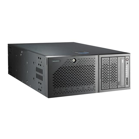
MAXDATA PLATINUM 5200 User manual

1MAXDATA PLATINUM 5200 Server Chassis
MAXDATA PLATINUM 5200 Server
Chassis
User’s Manual

2 3MAXDATA PLATINUM 5200 Server Chassis

2 3MAXDATA PLATINUM 5200 Server Chassis
Contents
1 Chassis Description ......................................................................................... 7
Kit Contents ............................................................................................................................. 7
Feature Summary .................................................................................................................... 7
Chassis Front View .................................................................................................................. 8
Front Panel Controls and Indicators .................................................................................... 9
Chassis Rear View ................................................................................................................. 11
Chassis Side View ................................................................................................................. 12
Peripherals ............................................................................................................................. 12
5.25-inch Removable Media Drive Bays ........................................................................... 12
5.25-inch Hard Drive Bays................................................................................................. 12
3.5-inch Hot-Swap Drive Bay ............................................................................................ 12
Power Supply......................................................................................................................... 13
Checking the Power Cords .................................................................................................... 14
Chassis Security .................................................................................................................... 14
Monitoring ............................................................................................................................. 14
Mechanical Locks .................................................................................................................. 15
2 Setting Up the Chassis .................................................................................17
Install the Chassis Feet (Pedestal Mode)............................................................................... 17
Install into a Rack (Rack Mode).............................................................................................. 18
3 Maintaining Your Server...............................................................................21
Tools and Supplies Needed ................................................................................................... 21
Safety: Before You Remove the Access Cover ..................................................................... 21
Warnings and Cautions.......................................................................................................... 21
Replacing Fans....................................................................................................................... 22
Replacing a Front System Fan .......................................................................................... 22
Replacing a Rear System Fan ........................................................................................... 23
Replacing the Power Supply.................................................................................................. 23
Hot-Swapping a Power Supply .............................................................................................. 24
4 Technical Reference ......................................................................................25
Power Supply Specifications.................................................................................................. 25
Input Voltages........................................................................................................................ 25
650 watt 2+1 power supply .............................................................................................. 25
Output Voltages..................................................................................................................... 25
System Environmental Specifications.................................................................................... 25
5 Product Regulatory Compliance Information ............................................. 27
Product Safety ....................................................................................................................... 27
Electromagnetic Compatibility (EMC) - Emissions................................................................. 27
Electromagnetic Compatibility - Immunity............................................................................. 27
Power Line Harmonics / Voltage Flicker ................................................................................ 27
Regional EMC Compliance Information................................................................................. 28

4 Contents
5MAXDATA PLATINUM 5200 Server Chassis
6 Important Safety Information ...................................................................... 29
Important Safety Information................................................................................................. 29
Intended Application Uses..................................................................................................... 29
Safety Instructions and Information....................................................................................... 29
Checking the Power Cords .................................................................................................... 29
Earth Grounded Socket-Outlets............................................................................................. 30
Before You Remove the Access Cover ................................................................................. 30
Fans ....................................................................................................................................... 30
Electrostatic Discharge (ESD) ................................................................................................ 30
Cooling and Airflow................................................................................................................ 31
Lifting and Moving ................................................................................................................. 31
Equipment Rack Precautions................................................................................................. 31
Anchor the Equipment Rack ............................................................................................. 31
Main AC Power Disconnect .............................................................................................. 31
Grounding the Rack Installation ........................................................................................ 31
Over Current Protection .................................................................................................... 31
Temperature Limits........................................................................................................... 31
Ventilation Considerations................................................................................................. 31
Backup Battery.................................................................................................................. 32

4 Contents
5MAXDATA PLATINUM 5200 Server Chassis
Figures
1. Screw Description .............................................................................................................. 7
2. Front View .......................................................................................................................... 8
3. Pedestal Controls and Indicators........................................................................................ 9
4. Rack Controls and Indicators.............................................................................................. 9
5. Rear View ......................................................................................................................... 11
6. Chassis Side View ............................................................................................................ 12
7. Power Supply ................................................................................................................... 13
8. Mechanical Locks............................................................................................................. 15
9. Installing the Chassis Feet ............................................................................................... 17
10. Attaching the Rail to the Chassis ..................................................................................... 18
11. Rails Installed in a Rack .................................................................................................... 18
12. Installing the Server into a Rack ....................................................................................... 19
13. Replacing a Front System Fan.......................................................................................... 22
14. Replacing a Rear System Fan........................................................................................... 23
15. Hot-Swapping a Power Supply......................................................................................... 24
Tables
1. Feature Summary............................................................................................................... 7
2. LED Description ............................................................................................................... 10
3. Redundancy LED Description........................................................................................... 13
4. Power Module LED Description....................................................................................... 14
5. Power Supply System Output Capability ......................................................................... 25
5. Environmental Specications ........................................................................................... 25
6. Product Regulatory Compliance Markings ....................................................................... 28
7. Regional EMC Compliance Information ........................................................................... 28
8. Safety Symbols ................................................................................................................ 29

6 Contents 7MAXDATA PLATINUM 5200 Server Chassis

6 Contents 7MAXDATA PLATINUM 5200 Server Chassis
1 Chassis Description
Kit Contents
The chassis subassembly kit includes a documentation CD-ROM that contains this Product
Guide; one power cord; and a box that includes four 5.25-inch external drive rails, a padlock
loop for securing the chassis, and four different types of mounting screws.
Figure 1. Screw Description
A. Flat head 6-32 x 5mm [.200] C. Hex head 6-32 x 6mm [.256]
B. Flat head M3 x 5mm [.200] D. Round head M4 x 8mm [.315]
Feature Summary
Table 1. Feature Summary
Feature Description
Drive Bays One 3.5-inch diskette drive bay, accessible from front.
Two 5.25-inch wide bays that are externally accessible, designed to hold half-height stan-
dard removable media devices; two of the bays can be converted into a single full-height
bay.
Two 5.25-inch wide bays that are not externally accessible, designed to hold half-height
IDE drives.
A hot-swap bay for 3.5-inch hard disk drives: space for up to five 1-inch high, SCA2 hard
drives.
Expansion slot
covers
Up to seven expansion slots can be used; every slot that does not have an add-in board
installed must have a slot cover installed.
Power supply 650 watt hot-swap redundant 2+1 PFC power supply.
Cooling Five hot-swap system fans: three inside the chassis and two on the rear.
Two power supply fans.

8 Chassis Description
9MAXDATA PLATINUM 5200 Server Chassis
Chassis Front View
Figure 2. Front View
A. Front panel controls and indicators
B. 5.25-inch removable media drive bays
C. Security lock (pedestal configuration)
D. Hot-swap drive carriers
E. Internal drive bays
F. Chassis intrusion switch
G. Diskette drive bay location
H. USB port
I. Front hot-swap system fan access door
J. Rear hot-swap system fans

8 Chassis Description
9MAXDATA PLATINUM 5200 Server Chassis
Front Panel Controls and Indicators
Figure 3. Pedestal Controls and Indicators
A. Hard drive activity LED EReset button
B. Power button F. LAN #2 activity LED
C. Sleep button G. Status LED
D. LAN #1 activity LED H. Power/Sleep LED
Figure 4. Rack Controls and Indicators
A. Hard drive activity LED F. ID button
B. Power button G. ID LED
C. Sleep button H. LAN #2 activity LED
D. LAN #1 activity LED I. Status LED
E. Reset button J. Power/sleep LED

10 Chassis Description
11MAXDATA PLATINUM 5200 Server Chassis
Table 2. LED Description
LED Name Color Condition Description
Hard drive activity Green BLINK Hard drive activity
Amber ON Fault
OFF No activity
LAN#1 activity Green ON Linked
Green BLINK LAN activity
OFF Disconnected
LAN#2-Link/Act Green ON Linked
Green BLINK LAN activity
OFF Disconnected
Status LED Green ON System ready
Green BLINK Processor or memory disabled
Amber ON Temperature or voltage critical fault; CPU/Terminator mis-
sing
Amber BLINK Power fault; Fan fault; Temperature or voltage non-critical
fault
OFF Fatal error during POST
Power/Sleep LED Green ON Power on
Amber ON Sleep (S1)
OFF Power off or Sleep (S4)
ID LED
(rack only)
Blue On Server identification; Toggled by ID button or software (rack-
mount system only)
OFF Server identification; Toggled by ID button or software (rack-
mount system only)

10 Chassis Description
11MAXDATA PLATINUM 5200 Server Chassis
Chassis Rear View
Figure 5. Rear View
A. AC input power connectors
B. Rear System Fans
C. ICMB or external SCSI connector knockout
D. Optional serial port*
E. Expansion slot covers
F. I/O ports*
G. Power supply module status LED (Green LED means proper operation)*
H. AC module Power Good LEDs (AC1, AC2, ACR; lit means proper operation)
I. Power supply modules
* Items shown may different in your chassis.

12 Chassis Description
13MAXDATA PLATINUM 5200 Server Chassis
Chassis Side View
Figure 6. Chassis Side View
A. 5.25-inch removable media drive bays
B. Diskette drive*
C. 5.25-inch hard drive bays
D. Hot-swap fan 5
E. Hot-swap fan 4
F. Hot-swap fan 3
G. PCI Area Duct
H. Processor Area Duct
I. Hot-swap fan 2
J. Hot-swap fan 1
K. Power supply
* Items shown may different in your chassis.
Peripherals
5.25-inch Removable Media Drive Bays
The upper bays are designed for removable media peripherals. You can install up to two
half-height peripherals or one full height peripheral. For proper cooling, the lowest position
must remain open.
5.25-inch Hard Drive Bays
The lower two drive bays are designed for hard drives.
3.5-inch Hot-Swap Drive Bay
The hot-swap drive bay supports up to ve 3.5-inch SCA LVDS hard drives. Five carriers
are included with the system. If no drive is installed in a carrier, a plastic air bafe must be
installed to ensure proper hard drive cooling.
The hot-swap drive bay accepts 1-inch hard drives that consume up to 18 watts of power.
Drives must be specied to operate at a maximum ambient temperature of 50º C. An optional
second Hot-Swap Drive Bay is available.

12 Chassis Description
13MAXDATA PLATINUM 5200 Server Chassis
Power Supply
The 650 watt, dual-line cord, 2+1 redundant power supply is auto ranging for either 100-120
VAC or 200-240 VAC.
The MAXDATA PLATINUM 5200 Server Chassis Hot-Swap, Redundant Power ships with
two power modules and a blank filler installed. A third power module (includes a second
power cable) can be ordered as an accessory .
NOTE
A redundant power configuration requires installation of three power modules and two
power cords.
Figure 7. Power Supply
A. Redundancy LEDs
B. Power Supply Module LEDs
C. AC Power Cord 1
D. AC Power Cord 2
Table 3. Redundancy LED Description
LED Name Color Condition Description
AC1 Green ON AC Power Cord 1 (AC1) active and modules 1 & 3 active
OFF No AC power to AC Power Cord 1
AC2 Green ON AC Power Cord 2 (AC2) active and modules 2 & 3 active
OFF No AC power to AC Power Cord 2
ACR Green ON Redundant Power active: all 3 modules active; both power
cords active
OFF Redundant Power not active

14 Chassis Description
15MAXDATA PLATINUM 5200 Server Chassis
Table 4. Power Module LED Description
LED Name Color Condition Description
Power Module
LED
Green ON Power supply DC outputs ON and OK
Green BLINK AC power present/Only Standby outputs ON
Amber ON Indicates one of these conditions:
• No AC power to this power supply module
• Power supply failure (includes over voltage, over temperature)
• Module current limit exceeded
Check Server Management Software to diagnose problem
OFF No AC Power to System
Checking the Power Cords
WARNING
Do not attempt to modify or use the supplied AC power cords if they are not the exact type
required.
The power supply cords are the main disconnect device to mains (AC power). The socket
outlet shall be installed near the equipment and shall be readily accessible.
If a power cord supplied with the chassis is not compatible with the AC wall outlet in your
region, get one that meets the following criteria:
• The cord must be rated for the available AC voltage and have a current rating that is at
least 125% of the current rating of the server.
• The connector that plugs into the wall outlet must be a grounding-type male plug
designed for use in your region. It must have certification marks showing certification
by an agency acceptable in your region.
• The connector that plugs into the AC receptacle on the power supply must be an IEC
320, sheet C13, type female connector.
• In Europe, the cord must be less than 4.5 meters (14.76 feet) long, and it must be flexible
<HAR> (harmonized) or VDE certified cordage to comply with the chassis’ safety certi-
fications.
Chassis Security
To help prevent unauthorized entry or use of the server, the chassis includes two chassis
intrusion switches that can be monitored by Server Management software, a padlock loop
at the rear of the chassis, and a front bezel door lock (pedestal only).
Monitoring
Two chassis intrusion switches are preinstalled. When the access cover is removed or the
front bezel door is opened, the switch transmits a signal to the BMC on the server board.
Server management software can be programmed to respond to an intrusion by powering
down or by locking the keyboard, for example.

14 Chassis Description
15MAXDATA PLATINUM 5200 Server Chassis
Mechanical Locks
A padlock loop on the rear of the chassis access cover can be used to prevent access to the
inside of the chassis. A variety of lock sizes can be accommodated by the .270 inch (7 mm)
diameter loop. The front bezel has a two-position lock to prevent access to the hard drives
and the interior of the chassis.
Figure 8. Mechanical Locks
A. Front bezel locked
B. Front bezel unlocked

16 Chassis Description 17MAXDATA PLATINUM 5200 Server Chassis

16 Chassis Description 17MAXDATA PLATINUM 5200 Server Chassis
2 Setting Up the Chassis
Install the Chassis Feet (Pedestal Mode)
If you are installing this server into a rack system, skip these steps and read the instructions
that came with your rack kit.
1. Move the chassis to the edge of your workbench.
2. Use four screws to attach each foot to the chassis. The holes in the feet will line up with
only one set of holes in the chassis. On the front foot, the middle hole should be towards
the front of the chassis. Hole locations for the front foot are marked “F” and “1,2”. On the
back foot, the middle hole should be towards the back of the chassis. Hole locations for the
rear foot are marked “F”.
3. You are now ready to attach a monitor, keyboard, and mouse to your server, and turn it on.
Figure 9. Installing the Chassis Feet
A. Screw hole
B. Chassis foot
C. Workbench
D. Screw (M4 round head)
D
�

18 Setting up the chassis
19MAXDATA PLATINUM 5200 Server Chassis
Install into a Rack (Rack Mode)
NOTE
Your chassis is designed to be compatible with the EIA-310-d rack standard. Be sure to
select a rack cabinet enclosure that is EIA-310-d compliant.
1. Fully extend the rails.
2. Remove the smallest and inner-most rail.
3. Position the rail.
4. Insert and tighten four screws.
Figure 10. Attaching the Rail to the Chassis
5. Install the rest of the rail in your rack.
Figure 11. Rails Installed in a Rack
A. Rack
B. Rail Assembly
C. Mounting Holes

18 Setting up the chassis
19MAXDATA PLATINUM 5200 Server Chassis
NOTE
Your rack may vary from the illustration. Refer to your rack documentation for information
specific to your rack.
6. Hold the chassis so the rails on the chassis engage the rails in your rack. You will need
someone to help you at this point.
7. Disengage the locking tab on each rail and slide the server into the rack.
Figure 12. Installing the Server into a Rack

20 Setting up the chassis 21MAXDATA PLATINUM 5200 Server Chassis
Table of contents
Popular Chassis manuals by other brands

National Instruments
National Instruments cDAQ 9188XT quick start

F5
F5 ARX 1000 Replacement

National Instruments
National Instruments CompactRIO cRIO-FRC Operating instructions and specifications

Juniper
Juniper PTX10008 quick start guide

InWin
InWin Cobra IW-RS212-07 user manual

Planet
Planet WMC-1600R user manual