MaxFlight MT3000 ELECTRIC User manual

1
MaxFlight
MT3000
“ELECTRIC”
Monster Truck Manual

2
MT3000 Monster Truck Directory
Section I: Operations Page8
CHAPTER 1: INTRODUCTION
1-1 Introduction to the electric MT3000 Page 9
1-2 Overview of the MT3000 Page 9
1-3 Overview of the Ride Selection System Page 9
1-4 Specific Ride Information Page 10
1-5 Ride Restrictions Page 10
1-6 Safety Page 10
CHAPTER 2: OPERATION
2-1 Description of Motion Page 11
2-2 System Startup Procedures Page 12
2-3 Game Start Procedures Page 12
2-4 Operation Control Icons Page 13
2-5 Game Over Page 13
2-6 Description of Customer Restraint System Page 13
2-7 Height and Weight Page 13
2-8 Game Selection Page 14
2-9 Customer Packets Page 14
2-10 Recommended Passenger Loading Procedures Page 14
2-11 System Shutdown Page 14
2-12 Emergency Stop Procedures Page 14
2-13 Power Interrupt and Re-Start Procedures Page 16
2-14 Ride and Facility Evacuation Procedure Page 16
2-15 Ride Termination Conditions Page 16
2-16 Daily Inspection Checklist Description Page 17

3
CHAPTER 3: SUGGESTED POSTINGS
This chapter contains notices that we suggest be placed near the unit to promote the safety of
patrons as well as operators and to ensure proper operation of the ride.
Introduction Page 17
Emergency Procedure Page 18
Emergency Raise Procedure Page 19
PatronNotice Page20
Daily Inspection Checklist Page 21
Site Configuration Requirements Page 22
Section II: Technical Page24
TABLE OF CONTENTS Technical
CHAPTER 1: GENERAL THEORY OF OPERATION
1-1 Introduction Page 24
1-2 Electrical Page 24
1-3 Mechanical Page 27
1-4 Computer System Page 27
1-5 What Causes the Unit To Page 28
1-6 Operating Limitations Page 30
CHAPTER 2: ELECTRICAL
2-1 Electrical System Page 30
2-2 Motion Platform Axis Page 32
2-3 Initial Wiring Confidence Test Page 33
2-4 Manual Control of Inverter Drives Page 34
2-5 Encoder Wiring Page 35
2-6 Mitsubishi Inverter Information Page 36
2-7 Inverter Replacement Page 37
2-8 Setting Inverter Parameters Page 37
2-9 Checking Inverter Alarm Stops Page 39
2-10 Frequency Control Parameters (Accessing) Page 39
2-11 Auto Tune of Inverter Circuits Page 43

4
CHAPTER 3: MECHANICAL
3-1 Mechanical System Page 44
3-2 Lift Component Installation Procedures Page 45
CHAPTER 4: COMPUTER SYSTEM/INTERFACE
4-1 Introduction Page 49
4-2 Hitachi Projector Settings Page 49
4-3 Layout Page 50
4-4 Troubleshooting Page 50
Pictures of Diagnostic Screens
Accessing Frequ. Control Part Numbers
Frequency Inverter Program Window
Auto Tune Program Window
OperatorPanel
OperatorPanel(RH)
Alert Window
Platform Motion Control Window
Motion Platform Window (Com)
New Player Window
Select Game Window
Select Level Window
Configuration Status Window
Devices (Config)
Devices 2 (Config)
Steering/Throttle (User Joystick 0)
Joystick Initial Setup Window
User Joystick Axes
User Joystick Sliders
Joystick Buttons
Address (Site)
EDS
Path Game Logs and Alert Logs
IODrivers
Direct Sound
Lock
Voodoo SST Video Properties

5
Voodoo Properties 1
Voodoo Properties 2
New Program/Platform motion Window
New Test Client and Switch Test window
Current Software window
Regedit32 windows
Software HKEY Local Machine (MF Motion Area)
LiftmotionEditor
Counterweight motion Editor
Pitch motion Editor
Pitch filter 1
Pitch filter 2 &3
Roll motion Editor
Roll filter 1 &2
Roll filter 3
CHAPTER 5: MAINTENANCE AND TROUBLESHOOTING
5-1 Required Daily Inspections Page 71
5-2 Weekly Maintenance Page 72
5-3 Inverter Maintenance Page 73
5-4 Extended Periods of non Use Page 74
5-5 Harsh Environmental Conditions Page 74
5-6 Cleaning of Cockpit and Consoles Page 75
5-7 Troubleshooting Page 75
5-7A Power Problems Page 75
5-7B No Computer Power Page 75
5-7C Cockpit Power Page 76
5-8 Video Problems Page 76
5-9 Audio Problems Page 77
5-10 If Unit Does Not Raise Page 77
5-11 Unit Does Not Counterbalance Page 78
5-12 Platform Lowered Sensor Page 78
5-13 Fails to raise level in pitch or roll Page 79
5-14 Occupant Safety Switch Page 79
5-15 Unit Stops Motion Page 79
5-16 No Roll or Pitch Movement when at the Top Page 79

6
5-17 Up Sensor Faults Page 79
5-18 Maintenance Warnings and Cautions Page 79
5-19 Maintenance and testing of Motors Page 80
5-20 Setup and Calibration of Joystick/CIB-1000 Page 80
5-21 Creating and configuring the Artificial Intel. (AI)
Joystick Devices Page 81
CHAPTER 6: Time Replacement Items
6-1 Introduction Page 82
6-2 Relays Page 84
6-3 Projector Bulbs Page 84
6-4 Non Destructive Testing Procedures Page 84
Attachment. 1Weekly Inspection Checklist Page 87
2 Cable Numbering and Routing Page 88
3 Electrical Circuits List Page 91
4 Hitachi Projector Settings Page 92
Part of Document Package
I: Mitsubishi Transistorized Inverter Manual
II: Hitachi Projector Manual
III: Sumitomo Motor and Gear Box Manual
IV: Warranty Cards for all Items
Section III: Installation Page94
TABLE OF CONTENTS INSTALL
CHAPTER 1: SET UP
1-1 Field Torque Procedure (Turn-of-the-Nut) Page 95
1-2 Assembly Instructions Page 95
ASSEMBLY DRAWINGS (SEE ”DRAWINGS FILE” )
DET-01 Power Box Page 100
DET-02A Right side Electrical Page 100
DET-02B Left Side Electrical Page 101
DET-04 Encoder Placement Page 101

7
DET-05 Platform Front Support Page 102
DET-06 Floor Plan\Accessories Page 102
DET-07 TV and Cabinetry Page 103
DET-08 Squaring the Ride Page 103
DET-09 Cabinetry Page 104
DET-010 Tail Cover and Stand Page 104
DET-011 Tail Closure/Pitch Motor Page 105
DET-013 Platform/Front Stand Page 105
DET-014 A frame Assy. Page 106
DET-015 Side A frame ABS Page 106
DET-016 Pitch shaft placement Page 107
DET-017 Pitch shaft Installation Page 107
DET-018 Safety Wiring Page 108
DET-022 Power Box Serial Interface Page 108
DET-035 CPU Card Layout Page 109
DET-036 CPU Card Layout MT,FS Page 109
DET-037 Mother Board Layout Page 110
DET-038 Lube Requirements Page 110
DET-039 MT Layout and spacing Page 111
DET-040 Lower Cockpit Fiberglass Page 111
DET-041 Lower ear ABS Page 112
DET-042 Upper rear ABS Page 112
DET-043A Lift Jack Clutch/Tower Page 113
DET-044 Pitch Rings Installation Page 113
DET-045 Roll Hub and Gear Box Page 114
DET-046 Cockpit Power Strip Page 114
DET-048 Lift cross drive system Page 115
DET-049 Cable routing to center Page 115
DET-050 Motion Control Card Jumpers settings Page 116
DET-051 MT,FS Command Console Layout Page 116
APPENDIX B: INSTALLATION & PERFORMANCE TESTING CHECKLIST
Page 117
Section IV: Drawings Start at Page 122
A.Electrical
B. Mechanical

8
MaxFlight
MT3000
“ELECTRIC”
Operators Manual

9
CHAPTER 1 – INTRODUCTION
1-1 Introduction to the MT3000
Welcome!! And thank you on your purchase of the MT3000 Monster Truck Simulator. The MT3000 is
the only full motion interactive networked experience of it’s kind. This is a dual seat monster truck
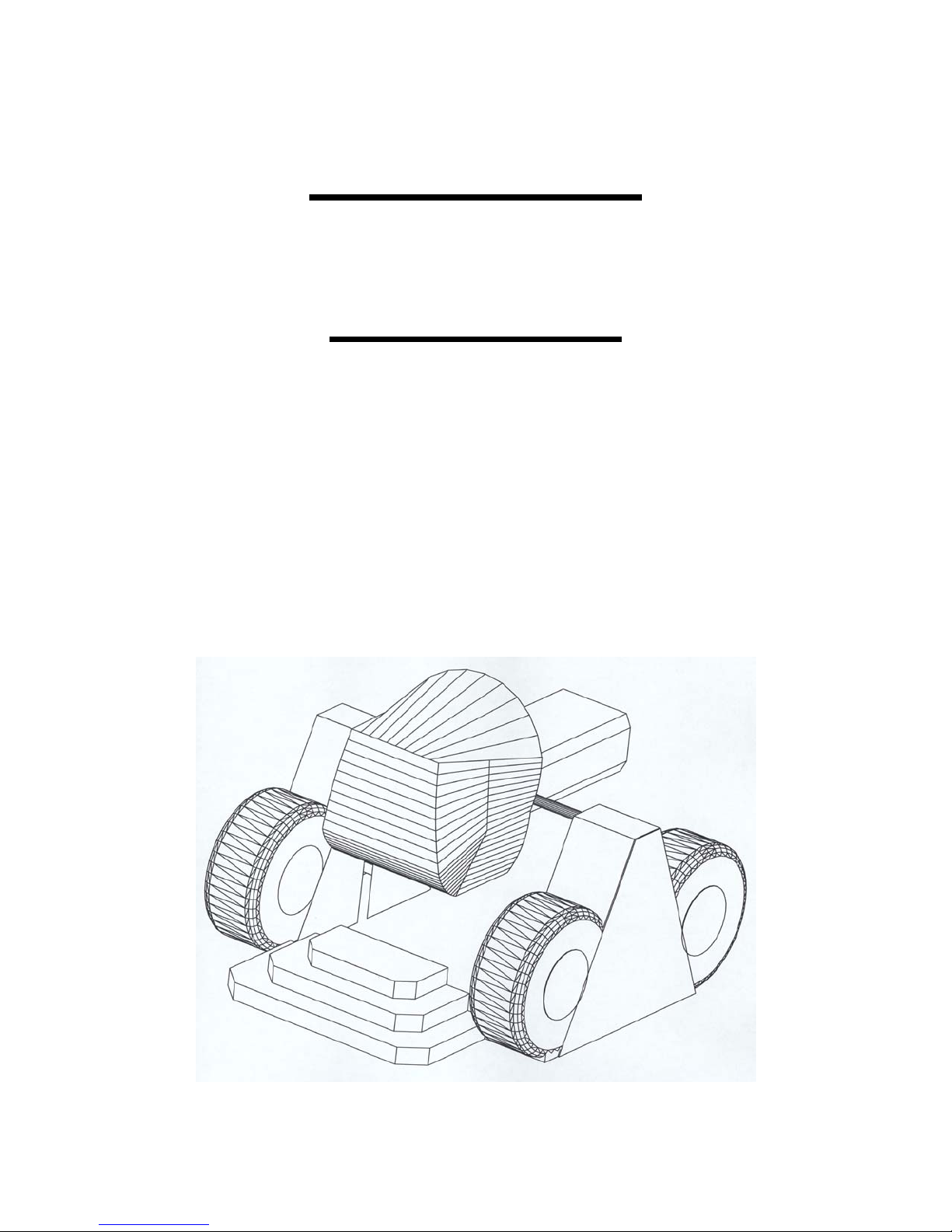
simulator based on a virtual reality environment with a full 360 degree, 2 axis motion platform. The
experience time can be varied according to patron demand while the standard time set is 6 minutes. You
can select from two track layouts thus making your ride as unique as possible.
1-2 Overview of the MT3000
The MT3000 is a computer driven monster truck simulator that provides a realistic monster truck driving
track.
1-3 Overview of the Ride Selection System
The customer can select their own track layout. There are two specific tracks that the
simulator can run on and they are: Monster truck arena, a series of jumps and bumps in a
confined space and the island road race, a open space environment with all the pitfalls of
real cross country driving. Whenever the terrain warrants a motion of the monster truck
it will emulate it to a degree of two motion flips. The (2) passenger cockpit is equipped
with a huge 58” projection screen and a pulse pounding surround sound system. Once
the cockpit is closed and locked, the passengers embark on a six minute (variable by
operator) default driving experience without the hassle of city traffic. A ride they will
never forget.
1-4 Specific Ride Information
This section has been included in your manual to give you specific and detailed information about the
MT3000 Monster Truck Simulator. This information complies with the ASTM 698-94 standard (American
Society for Testing and Materials) which governs Physical Information to be provided for Amusement
Rides and Devices.
Ride Speed: Pitch Axis - 90 Degrees per second (15RPM)
Roll Axis - 90 Degrees per second (15 RPM)
Direction of Travel: Pitch – 360 Degrees
Roll – 360 Degrees
Vertical axis (Y-axis)
Maximum passenger capacity by weight per passenger position: 250 lbs.
Maximum passenger capacity by weight per the total device: 500 lbs.
Maximum passenger capacity by number per the total device: 2
Duration of passenger exposure: Up to six minutes
Passenger weight distribution: Maximum Unbalance – 100 lbs.
Environmental restrictions: Stable Environment – Temperatures less than 80°F,
Humidity less than 60%

10
Recommended passenger restrictions: Minimum Height – 48”
Mechanical power requirements: The pitch movement is powered by a 5 HP electric
motor.
The roll movement is powered by a 3.0 HP electric
motor.
The lift movement is powered by a 3 HP electric
motor.
Static information: Height:7’ 9” (approx.)
Width: 12’ 8” (approx.)
Length: 15’ (approx.)
Weight: 4800 lbs.
Dynamic information:Height:12’ 10” (approx.)
Width: 12’ 8” (approx.)
Length: 15’ (approx.)
Weight: 5300 lbs. maximum
Fastener schedule: Refer to the MaxFlight MT3000 Installation Manual
Maximum static load distribution per footing: NS – based on static weight distributed by
(4) 8” x 16” feet and
(2) 4” x 14” feet
INA = Information Not Available N/A = Not Applicable UNK = Unknown NS =
Not Specified
1-5 Ride Restrictions
There are certain conditions that the machines should not be operated under. These conditions are
described below.
1-5A Intoxication
If a patron is under the influence of any drugs or alcohol they should not be allowed to utilize the
equipment. If a question arises have a manager speak to the patron.
1-5B Heart Conditions
Any heart or other similar condition would preclude a passenger from riding the simulator.
1-5C Pregnancy
It is not recommended that women who are pregnant ride the simulator.
1-5D Weight and Height Restrictions
The patrons must be at least 48” (1.22 m) tall and total weight is not to exceed 500 lb. (226.8 kg) with no
more than a 100 lb. (45.36 kg) difference between the passengers. All patrons must be capable of sitting
normally in the seat and be capable of using all the restraint devices available and mandatory. If this
is not possible the patron cannot ride.
1-5E Impairments
We recommend that patrons with the following impairments/conditions do not ride the VR2002 Cyber
Coaster:

11
♦ Head, neck, heart or back problems
♦ Recent operations
♦ High blood pressure
♦ Motion sickness
♦ Women who are pregnant
♦ Epileptic patrons; due to the special strobe and lighting effects that are
known to trigger seizures
♦ Intoxicated patrons
♦ Claustrophobia
1-6 Safety
Due to the nature of the MT3000 there are several safety precautions that must be observed in order to
ensure the safety of both the patrons and the operators during operation of the experience.
1-6A Ensure that the cockpit has completed movement prior to continuing with any
other procedures.
1-6B NOTE: Ensure that during the time of operation, all persons must stay clear of
the simulator in order to prevent injuries.
1-6C Ensure that the operating personnel do not operate the simulator with any of the
cover plates removed.
1-6D Ensure that only authorized personnel open the power distribution box for any
reason.
1-6E Ensure that patrons pass the height and weight requirements to ride the simulator.
1-6F Queue Line Safety
The queue line must be kept orderly. The patrons must remain behind the established
barriers while waiting their turn to ride. The queue line should also be used to familiarize
patrons with the operation of the Occupant Panic Switch (OPS) Button.
1-6G Loading/Unloading Safety
During the loading and unloading of patrons, the operator must ensure that the simulator
has come to a complete stop prior to opening the cockpit. The operator is required to
assist the patrons to negotiate the steps and cockpit.
1-6H During the operation of the simulator, the operator must stay within the proximity
of their assigned units. Operators must watch for such things as equipment failure, abuse
of the simulator and customers who wish to terminate game play.
1-6I During the operation of the ride, the operator(s) should be posted at the control
console where the computer screen, mouse and unit will be in his/her direct line of sight

12
CHAPTER 2 – OPERATION
2-1 Description of Motion During Operation
There are three basic axes of motion that the simulator travels on, Pitch, Roll and vertical lift into the game
position.
2-1A The Pitch Axis
The pitch motor is a 5 HP 208 VAC drive motor. Controlled by the frequency drive inverters. The pitch
axis will rotate the cockpit in either a clockwise or counterclockwise direction. The maximum velocity the
pitch axis will produce is 90 degrees per second.
2-1B The Roll Axis
The roll motor is a 3.0 HP 208 VAC drive motor. Controlled by the frequency drive
inverters. The roll axis will rotate the cockpit in either a clockwise or counterclockwise
direction. The maximum velocity the roll axis will produce is 90 degrees per second.
2-1C The Vertical Lift System
The Lift motor is a 3.0 HP 208 VAC drive motor. Controlled by the frequency drive inverter. The vertical
lift system raises and lowers the main assembly into the load and ride positions.
2-2 System Startup Procedures
The procedures listed below must be followed to ensure the simulator operates in a safe
condition.
1. Turn “ON” the MAIN power strip located in lower right of the command
console.
2. Turn “ON” the UPS, green light on steady.
3. Turn “ON” the pre-amp and main amp if not on.
4. Turn the computer to “ON” and allow the system to boot up to the desktop
window.
5. Turn the Cockpit power “ON” on the power strip located inside left rear A
frame area.
6. Pull out the red “E-Stop” button located on left side of command console, this
closes the power contactor enabling the inverters.
7. Turn TV power to “ON”.
8. Turn remote viewer system “ON” if used.
NOTE: The bird and an alert window will open while the inverters are powering up and
the communication path between the CPU and power box is established. If all is well, the
bird and window will close. If there is a problem, another alert window will come up
stating the problem. Correct all faults before running/starting any other program.
2-2A Description of Control Windows and Icons
A. Desktop Displays
• “Maxzilla” icon- shortcut to the actual program, double clicking it
will initiate the program.

13
• “Mitsubishi Inverter Test” icon- shortcut to the manual test of the
inverters in all axes. This is the icon used for the emergency raise
procedure.
• “Mitsubishi Test” icon- shortcut to the semi-automatic maintenance
test program of the platform.
• ‘Game Log” icon- shortcut to the recorded game log.
• “Start” icon- lower left, initiates system shutdown or other internal
CPU functions.
• “VFD” icon- shortcut to the Inverter Frequency Control Setup and
Test Program.
B. Game Program Windows and Icons
1. Maxzilla Program Window
a. “New Game” opens game setup window
(1) Game Setup Window
(a). Single Player- select if no remote viewer is
used
(b). Multiplayer Host- select if remote viewer is
used
© Multiplayer Client – select only if setting up
remote viewer CPU
(d) “OK” select and go to next window
b. Track Setup Window
(1) Monstertruck Arena – closed circuit arena with
jumps
(2) Island Data Base – open country and mountain trails
(3) “OK” goes to next window
c. Loading Play Area Window – loads selected scenario into
CPU RAM for play
d. New Player” icon – opens truck type and time selection
window
(1) Select Track if change takes @ 2 minutes to load
(2) Select Time - default is 6 minutes, can be changed
as desired
(3) “OK” goes to next window
e. Recover Truck – when pushed brings flipped over truck
upright
f. Back to Track - when pushed returns truck to the trail
g. Top Row Indicators
(1) GAME
STOP – stops selected program
QUIT – shuts selected program down completely,
clears memory

14
2. “Maxflight Base Lift Control” window
a. Raise icon – allows the platform to raise, balance normal
and go to the top.
b. Stop icon – stops motion of the platform at any point.
c. Lower icon – allows the platform to lower to the steps level
normal.
2-3 Description of Passenger Restraint System
There are two restraint systems employed for passenger comfort and safety, a primary
and a secondary.
2-3A Primary Restraint
The primary restraint system is similar to an Airline safety belt. It simply pulls around
the passenger and plugs into the receptacle. It is then tightened with the pulling of the
strap.
2-3B Secondary Restraint
The secondary restraint system consists of a molded structural steel bar shaped to fit the
passenger. The bars are covered with padding and vinyl covers for passenger comfort.
Once lowered into place, the passengers cannot release themselves, preventing
inadvertent discharge. To operate, lower the harness to the patrons comfort, then check it
for security and that it is locked.
2-4 Height and Weight
Maximum total weight for the ride is 500 lbs. (226.8 kg) with no more than a 100 lb. (45.4 kg)
difference between the passengers.
Minimum height requirement for the ride is 48 in. (1.22 m)
2-5 Game Selection
Patrons should be encouraged to make their game selections while waiting in the queue line.
2-6 Customer Pockets
The attendant must ask each patron if they have any objects in their pockets that could
come out during the ride. If so, remove and place the items in a secure container for the
duration of the ride. Be sure to remind patrons at the end of their ride to retrieve their
possessions.
2-7 Recommended Passenger Loading Procedures
Assist the passenger into the cockpit and tell them to put on the primary restraint (the
seatbelt). Lower the restraint harness until it is snug against the waist and chest. Render
any assistance or instructions required. This is a good time to give the patrons
instructions on how to use the Occupant Panic Switch and the controls/operations of the
Steering Wheel, Gas pedal, Brake pedal, and Fwd/Rev Shifter. After it has been
explained, they should be asked if they understand how to use these items. Close the
canopy and secure it with the locking devise.

15
2-8 Game Start Procedures
2-8A Initial Game Startup
1. Double click on “Maxzilla” icon and the program will initiate and open
program window.
2. Click on “NEW GAME” another selection window opens up.
3. Click on SINGLE PLAYER – if remote viewer is not used.
MMULTIPLAYER HOST – if remote viewer is used.
4. Game Setup window opens, select either MONSTERTRUCK
ARENA or ISLAND DATA BASE. Highlight by clicking on
selection the click “OK”
5. CPU loads the game data and opens the “MAXFLIGHT BASE LIFT
CONTROL” window lower right of screen.
6. Select “NEW PLAYER”, select truck type and time. Time default is 6
minutes but can be changed.
7. Select “OK”
8. Raise the platform to the run position. Click RAISE lower right window.
2-8B Raising the Unit
Ensure that power is applied and normal program is loaded. Go to the LIFT CONTROL, click on the
“RAISE” icon. The unit will come up about two (2) inches and stop to balance. Upon completion of
balancing, the unit will continue raising up to the upper limit switches. If the unit does not balance within
one (1) minute, lower the unit and retry.
NOTE: The weight limit is 500 pounds.
2-8C Game Start
Game will start when normally raised to the top after a game is selected. When the platform reaches the
upper limit switches the CPU will enable the program and full motion is enabled.
2-9 Game Over
When the time runs out, the game window timer will be zero, the “LOWER
PLATFORM” icon will highlight. During this time the unit will return to “HOME
POSITION”. Click on the “LOWER” icon and after the unit has lowered onto the
stairway, and movement has stopped, discharge the patrons.
2-10 System Shutdown
At the end of the operating day, follow these procedures to ensure that the simulator is
safely secured for the day.
1. Lower the passenger restraint harness to the down position.
2. Lock the seat belts together.
3. Lower and latch canopy.
4. Press the E-Stop on side of console IN. Removes all motor power and locks
the brakes.
5. Select GAME top left
6. Select STOP
7. Select GAME again

16
8. Select QUIT program is now completely terminated
9. Select START lower left
10. Select SHUTDOWN
11. Select OK
12. After CPU has shut down and monitor is off press Main Power switch on
power strip to OFF
13. Turn the UPS power switch to OFF green light out
14. Turn Cockpit power OFF on power strip.
The system is now secured.
2-11 Emergency Stop Procedures
In the event of an emergency follow the procedures described below for the type of emergency.
2-11A Occupant Panic Switch
During the ride the patrons have the ability to initiate a ride abort by depressing the
Occupant Panic Switch (Labeled “Safety Stop” in the cockpit). When this switch is
depressed the ride will return to the “home” position, the video projector will freeze and
the sound will stop. Once the unit is level, lower the unit by clicking the “lower” icon on
the computer screen. When the unit is completely lowered onto the stairway, open the
cockpit door and ask the riders if they would like to continue. If they do not which to
continue, discharge the passengers following the Passenger Unloading Procedure. If they
wish to continue, close the canopy and secure it with the locking device. Click on the
“raise” icon and once the unit is completely balanced it will raise to top and continue.
2-11B Emergency Termination Procedures
In the event of an emergency not involving the simulator directly, click on the ‘STOP” icon on the screen.
Wait for the unit to level, and then lower the platform as normal. In the event that the unit is not
responding to the commands, use the Red EMERGENCY STOP BUTTON on the side of the Command
Consol to terminate power to the electric motors. The unit will then have to be leveled and lowered
manually as described in section 2-11C. Assist the patrons out of the simulator and direct them to the exit.
2-11C Emergency Stop without Electrical Power
The Red EMERGENCY STOP BUTTON on the side of the Command Consol must be depressed
IMMEDIATELY; this will disable the Electric Motors and set the manual brakes. Level the unit on both
the pitch and roll axis manually as described in section 2-11C. Using the manual BRAKE RELEASE on
the back of the lift motor, slowly lower the unit to the base. Open the canopy and release the restraint
harness and assist patrons from the cockpit.
Fig. 1 Fig. 2
2-11D Emergency Leveling and
Lowering
To level the machine in the pitch axis pull on the
PITCH BREAK RELEASE (Fig. 1) and level the
machine manually. There is a level mounted on
the Roll Motor (Fig. 2) to aid in getting the ride
into the home position. A Second person should
be used when performing this procedure.

17
Fig. 3 Fig. 4
To level the machine in the roll axis
move the manual BREAK RELEASE
LEVER (Fig. 3) towards the Tail
Boom Cover. There is another level
mounted on the back of the seat frame
(Fig. 4) to help find home level in the
Roll axis.
Fig. 5
Once the machine is in the HOME position (level on both pitch and roll
axis) it can be lowered. Using the manual BREAK RELEASE KNOB on
the back of the Lift Motor (Fig. 5), Slowly turn the knob clockwise until
the platform lowers from the elevated position. Adjust lowering speed by
the amount you turn the knob. Releasing of the knob will stop the
lowering.
CAUTION: WHEN LOWERING UNIT MANUALLY, ALLOW UNIT
TO COME TO A SLOW, SMOOTH STOP.
2-12 Power Interruptions and Restart Procedures
Should the power be interrupted, the following procedures should be followed.
2-12A Facility Emergency Lighting
Facility emergency lighting must be configured to allow attendants and patrons enough lighting to safely
exit the ride and area.
2-12B Restart Procedures
Even if the power comes back on, lower the platform to its full down position, using the manual lowering
procedure para. 2-11C. If the power is normal, you can follow the normal Start-up procedures para 2-
2.
2-13 Ride and Facility Evacuation Procedure
Terminate the ride from the PC. Quietly and calmly, have the queue line begin exiting the facility. Lower
the unit(s) open and unbuckle all patrons and assist with the evacuation of the facility. Follow the system
shut down procedure if time permits or at least press the “E-Stop” this removes power to the electric
motors. NOTE: It is most important that the power to the motors is disabled.
2-14 Ride Termination Conditions
1. Any abnormal vibration or abrupt motion changes that would not be considered part of the normal
operation.
2. Any undue movement of either the fiberglass, covering panels, A-frames or any hinges or fabricated
metal that would indicate fatigue, fracture or loose bolts.
3. Any type of electrical problem that would effect continuation of the game and could include electrical
problems within the building that could inadvertently affect the operation of the simulator.
4. Any computer malfunction that would include system lock-up, program termination or any other
condition that would affect game play.

18
5. Any condition with the movement that is abnormal (i.e. the TV set showing a roll where the simulator
remains stationary).
6. Any loose objects that roll around inside the cockpit as these items would damage the patron as well as
the components inside the cockpit.
7. Any signs that the concrete anchors may be loose by allowing the unit to walk or move.
8. Any signs of smoke or sparks which would indicate the potential for fire.
9. Any condition where the passenger was tampering with the system such as pounding on the fiberglass
or undue pressure on the cockpit.
2-15 Operational Restrictions
There are certain conditions that the machines should not be operated under. These conditions are
described below.
2-15A Intoxication
If a patron is under the influence of any drugs or alcohol they should not be allowed to utilize the
equipment.
2-15B Heart Conditions
Any heart or other similar condition would preclude a passenger from riding the simulator.
2-15C Pregnancy
It is not recommended that women who are pregnant ride the simulator.
2-15D Weight and Height Restrictions
The patrons must be at least 48” (1.22 m) tall and total weight is not to exceed 500 lb. (226.8 kg) with no
more than a 100 lb. (45.36 kg) difference between the passengers.
2-15E Electrical Storms
It is up to the discretion of the owner operator to operate during an electrical storm. However, it is NOT
recommended to rely on the internal facility safe guards to protect the equipment. When in doubt, shut
down the system to ensure safety of not only the passengers but also the safety of the system.
2-16 Daily Inspection Checklist Description
The Daily Checklist is to be completed by the first shift attendant operating the MT3000 as well as the
second shift attendant (if applicable) at the beginning of his/her shift. These sheets must be filled out on a
daily basis. DO NOT check off the items in the checklist unless you have performed the required
inspection. This maintenance is required to maintain optimum performance of the MT3000. The master
copy of this checklist can be found at the end of the Operator’s Manual.
CHAPTER 3 – SUGGESTED POSTINGS
This chapter contains notices that we suggest be placed near the unit to promote the
safety of patrons as well as operators and to ensure proper operation of the ride.

19
EMERGENCY PROCEDURE
POSTINGS
Emergency Stop Procedure
The Red Emergency Stop Button, located on the side of the command consol, MUST be depressed
IMMEDIATELY. This will deactivate the Electric Motors. The unit will need to be leveled manually on
both the Pitch and Roll axes. Located on the back of the Lift Motor is the manual brake release knob.
SLOWLY turn the knob clockwise until the unit lowers from the elevated position. Adjust the lowering
speed by the amount you turn the knob. After the ride has lowered, open the canopy, raise the harness
restraints and aide the patrons in exiting if necessary.
Ride and Facility Evacuation Procedure
Terminate Game Play from the host PC.
Quietly and calmly, have the Queue line
begin exiting the facility. Lower the
unit, open the canopy, raise the
harness(s) and unbuckle the patron(s),
then assist with the evacuation of the
facility.

20
NEW EMERGENCY RAISE
PROCEDURES
FOR
ELECTRIC MACHINES
This Emergency Procedure to be used anytime if/when the Motion Platform lowers in a
abnormal way, ie: Contacts the stands, floor or is stuck half way between all the way UP
or DWN.
1. Anytime an abnormal action occurs on the motion platform the operator
MUST immediately depress the E-Stop on the side of the command console.
2. Verify that the E-Stop is depressed.
3. On the Lower Right corner of the Task Bar right click with the mouse on the
icon that contains a checkmark in a green circle. This opens a Properties
window.
4. Click on Emergency Raise, another control window will open up showing a
STOP and RAISE icon.
5. Pull out the E-Stop on side of command console. Verify immediately that
there is no motion on the platform. If there is push E-Stop back in
immediately and then back out, this will reset the brakes on all drive motors.
6. Click on RAISE icon, the unit platform will rise approximately ½ to ¾ of an
inch at a time. It will do so until it contacts the upper limit sensors and stop.
7. When motion platform is all the way UP, DEPRESS E-STOP.
8. Manually level the platform in Pitch and Roll.
9. Lower the platform using the manual lowering procedure, by turning the brake
lever on rear of lift motor clockwise slowly until the platform lowers.
10. Lower all the way. When down on the stands open the cockpit and help
patrons out.
11. Call Maintenance for repair and/or unit testing to certify that this unit is safe
to operate.
Table of contents
Popular Toy manuals by other brands

Eduard
Eduard B-26 Marauder upgrade set manual

Nexa
Nexa Dago red Unlimited Air Racer 4 instruction manual

Craycle Hobby
Craycle Hobby Ranger Sport user guide

Top Flite
Top Flite Focke-Wulf 190 D9 instruction manual

Radica Games
Radica Games 76014 instruction manual

Fisher-Price
Fisher-Price R7146 quick start guide

The Singing Machine
The Singing Machine SMK198 instruction manual

Supertrax
Supertrax Maybach Style Kids Ride on Car Installation and operation instructions

Fisher-Price
Fisher-Price DWC31 owner's manual

Eduard
Eduard Zoom SS396 Assembly instructions

LM model
LM model F-4U Corsair user manual

LEGO
LEGO City 60052 Building instructions