manuals.online logo
Brands
  1. Home
  2. •
  3. Brands
  4. •
  5. MaxiiNet
  6. •
  7. Switch
  8. •
  9. MaxiiNet Vi3405 User manual

MaxiiNet Vi3405 User manual

Application Drawings
Vi3405 5-Port L2 PoE Coax Switch Installation Manual
DO NOT OPEN
RISK OF ELECTRIC SHOCK
CAUTION
CAUTION: TO REDUCE THE RISK OF ELECTRICAL SHOCK,
DO NOT REMOVE COVER. NO USER SERVICEABLE
PARTS INSIDE. REFER SERVICING TO QUALIFIED
SERVICE PERSONNEL.
IP Camera-end Installation
The Smart Choice for Transmission Solutions www.vigitron.com
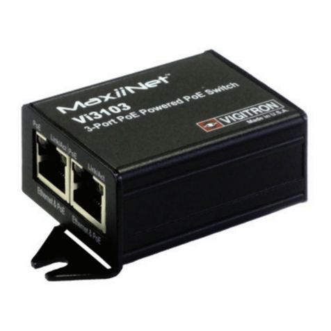
Vigitron’s MaxiiNet™ Vi3405 fixed managed five port extended Coax PoE
switch brings new performance standards to the growing need for high
speed transmission of high speed Ethernet. It eliminates the need for local
power for the cameras connected to its 4 ports at extended distances. The
Vi3405 provides a 100Base-T and an SFP socket for fiber optic uplink.
The Vi3405 is powered locally by the Vi1120 to supply 802.3at to each port,
providing up to 36W (802.3at) to each port. The Vi3405 can operate over
Coax cables at extended distances up to 1,800 feet (548m) when combined
with the Vi2401A or Vi2400A.
With an operating temperature range of -30°C to 75°C, the Vi3405 is the
perfect solution for data and power transmission for warehouses, parking
lots, campuses, casinos, and many more. The Vi3405 is MegaPixel Certified
(MPC™), type tested to network packet performance standards, and major
manufacturer compatibility tested to assure you error free, quality opera-
tions. Fixed managed L2 functions include 802.1p Qos, support of 2k MAC
addressing, learning, aging, and a non-blocking switch fabric.
Installation cost savings, proven performance, and major camera manufac-
turer compatibility all go into making Vigitron’s MaxiiNet™ Vi3405 an ideal
solution for standard distance data and power transmission.
Important Safety Warning
Ethernet Switch/NVR-end Installation
- Read and keep these instructions.
- Heed all warnings.
- Follow all instructions.
- Do not use this apparatus near water.
- Clean only with a dry cloth.
- Install in accordance with the manufacturer’s instructions.
- This installation should be made by a qualified service person and should conform to all local
codes.
- DO NOT bundle UTP or Coax signals in the same conduit as high-voltage wiring.
- To reduce the risk of fire or electrical shock, do not expose these products to rain, moisture,
dripping or splashing.
- No objects filled with liquids, such as vases, shall be placed on Vigitron equipment.
- DO NOT install the unit in a place where the operating ambient temperature exceeds 75°C or
is below - 40°C.
- Make sure that the external power supply output voltage is in the recommended range.
- Do not install near any heat sources such as radiators, heat registers, stoves or other
apparatus (including DVRs) that produce heat.
- Protect the power cord from being walked on or pinched particularly at power source,
convenience receptacles, and the point where they exit from the apparatus.
- Only use attachments/accessories specified by the manufacturer.
- Unplug this apparatus during lightning storms or when unused for long periods of time.
- Refer all servicing to qualified service personnel. Servicing is required when the apparatus
has been damaged in any way, such as when a power supply cord or plug is damaged, liquid
has been spilled, objects have fallen inside the apparatus, the apparatus has been exposed
to rain or moisture, does not operate normally, or has been dropped.
- The main plug is used as the disconnect device and shall remain readily operable.
WARNING! - To reduce the risk of fire or electric shock, do not expose
this apparatus to rain or moisture. This apparatus shall not be exposed to
dripping or splashing and no objects filled with liquids, such as vases shall
be placed on the apparatus.
WARNING! - This apparatus is a Class I product. This product must
be connected to a mains socket outlet thru an AC to DC Power supply.
WARNING! - The mains plug is used as the disconnect device and
shall remain readily operable.
Uplink Connections:
There are 2 ways to connect the Vi3405 Uplink to another network switch or
an NVR, either fiber optics or Standard UTP Ethernet. Only one of these
ports can be active at the time.
a) Standard Ethernet RJ45 connector
- Connect the Uplink RJ45 connector of the Vi3405 to a standard Cat5/6
cable of maximum 328 feet (100m). Connect the other end of the cable to
the Ethernet port of the other network switch.
b) Fiber optics
-If you want to use fiber optics first you need to insert a suitable SFP that
matches your fiber optic cable into the Uplink SFP socket of the Vi3405.
Then connect the fiber optics cable to the SFP. Connect the other end of
SFP to the optical connector of the other network switch.
Power Supply:
-Connect a power supply to the power input of Vi3405. If there is no need
for providing PoE on 4 ports, a 12VDC power supply such as Vi0012 will be
sufficient. If PoE is required at the ports you need to select a 48-57VDC
power supply such as Vi1120 that can provide maximum PoE capacity on
all 4 ports.
Extended Ethernet Ports:
- Connect a standard Cat5, or better, UTP cable of maximum 3,000 feet
(914m) to one of the Ethernet ports. The ports will automatically configure
as 10 or 100BaseT depending on the distance.
- Use an Ethernet and PoE “Extender” such as Vi2401A or Vi2400A at the
camera side.
- Connect one end of the long Coax cable to the BNC connector of Extended
port of “Extender”.
Non-PoE Switch
Connecting Cameras over combination of Coax and Fiber cables
Fiber Optic
Cat 5/6
Coax
Vi3405
Power
Supply
Vi2400A
Vi2400A
Vi2401A
IP Cameras
IP Cameras
IP Cameras
Vi2401A
The Vi3405 can be used to connect remote cameras over a combination of Coax and Fiber cables.
Data
Fiber up to 80Km
Data + PoE
328 ft. (100m)
Data + PoE
328 ft. (100m)
Data + PoE
328 ft. (100m)
Data + PoE
3,000 ft. (914m)
Data + PoE
3,000 ft. (914m)
Data + PoE
3,000 ft. (914m)
Data + PoE
3,000 ft. (914m)
Data + PoE
328 ft. (100m)
Non-PoE Switch
Connecting Cameras over combination of Coax and UTP cables
Vi3405
Power
Supply Vi2400A
Vi2400A
Vi2401A
IP Cameras
IP Cameras
IP Cameras
Vi2401A
The Vi3405 can be used to connect remote cameras over a combination of Coax and UTP cables.
Data
328 ft. (100m)
Data + PoE
328 ft. (100m)
Data + PoE
328 ft. (100m)
Data + PoE
328 ft. (100m)
Data + PoE
3,000 ft. (914m)
Data + PoE
3,000 ft. (914m)
Data + PoE
3,000 ft. (914m)
Data + PoE
3,000 ft. (914m)
Data + PoE
328 ft. (100m)
Maxii
Net
TM
Limited Lifetime Warranty
Vigitron, Inc. warrants that all Vigitron products (“Product”), if used in accordance
with these instructions, will be free of defects in material and workmanship for
lifetime defined as the duration period of time until product end of life is
announcement. After which Vigitron will continue to provide warranty services for a
period of 3 years. Period covering valid warranty will be determined by proof of
purchase in the form of an invoice from an authorized Vigitron dealer.
Warranty will only be provided for as long as the original end user purchaser owns
the product. Warranty is not transferable. At Vigitron's option, defective product will
be repaired, replaced or substituted with a product of equal value. This warranty
does not apply if, in the judgment of Vigitron, Inc., the Product fails due to damage
from shipment, handling, storage, accident, abuse or misuse, or if it has been used
or maintained not conforming to Product manual instructions, has been modified, or
serial number removed or defaced. Repair by anyone other than Vigitron, Inc. or an
approved agent will void this warranty. Vigitron, Inc. shall not under any
circumstances be liable to any person for any incidental, indirect or consequential
damages, including damages resulting from use or malfunction of the product, loss
of profits or revenues or costs of replacement goods. The maximum liability of
Vigitron, Inc. under this warranty is limited to the original purchase price of the
Product only.
Prior to returning any defective Product, the end customer or the reseller from whom
the end customer originally purchased the Product must obtain a Return Materials
Authorization (RMA) number from Vigitron, Inc. All defective Products should be
returned to Vigitron, Inc. with shipping charges prepaid. No collect shipments will be
accepted.
Technical Specifications*
RoHS
Drawings
Status LEDs
© Copyright 2022 Vigitron, Inc.
TEL (+1) 858 - 484 - 5209 • FAX (+1) 858 - 484 - 1205
7810 Trade Street, Suite 100, San Diego, CA 92121, USA • [email protected] • www.vigitron.com
Vi3405_UM
LED Name Color Status Function
OFF Power is OFF
ON Power is ON
OFF No Traffic
FLASHING Traffic
GREEN ON Connection is OK, 10BaseT Mode
ORANGE ON Connection is OK, 100BaseT Mode
OFF No connection
FLASHING Connection is OK with Traffic
Link/Act
(Standard Side)
Power GREEN
Traffic
(Extended Side) YELLOW
10/100 BaseT
(Extended Side)
Ordering Information
YELLOW
Electrical
Ethernet Interface Standard 10/100BaseT
Uplink UTP: 100 Ohm +/- 20%, up to 328 ft. (100m)
Fiber Optics: will depend on the type SFP and Optical cable
Power Source External Power Supply: 57VDC @ up to 120W
Status LEDs Power
Ethernet: Traffic, Link
PoE Active
Connectors Fiber: MSA compliant SFP socket
Ethernet Interface: 1 x RJ45
Ethernet Extended Interface: 4 X BNC
Power: Circular power connector
RFC 2544 TCP/IP Packet Transmission
RFC 768 UDP, 2068 HTTP, 793 TCP
791 IP, 1783 TFTP, 894 IP over Ethernet
PoE Compatibility IEEE 802.3af, IEEE 802.3at
Data Interfaces & RFC 768 UDP, RFC 2068 HTTP
Compliances RFC 793 TCP, RFC 791 IP
RFC 1783 TFTP, RFC 894 IP over Ethernet
RFC 2544 TCP/IP Packet Transmission
IEEE802.3af, 8IEEE02.3at
IEEE Compliances 802.3ab, 802.3z, 802.3af, 802.3at, 802.1p,
802.1Q, 802.1D, 802.1s, 802.3u, 802.3x, 802.3w
Service IPv4 Type of Service (TOS) & Differentiated Services (Diff-Serv)
Compliance IPv6 Traffic Class
Regulatory
Safety CE
Environmental RoHS, WEEE
Environmental
Humidity 0 to 95%, non-condensing
Temperature Operating: -30°C to +75°C
Storage: -40°C to +85°C
Mechanical
Dimensions 1.2x3.75x5.1 in., 3.0x9.5x13 cm (HxWxL)
Weight 0.76 lb (344 g)
Housing Aluminum
Optional Accessories
Vi1120: 57VDC, 120W Power Supply
Vi0017: 48VDC, 40W Power Supply
Vi0012: 12VDC, 12W Power Supply for non-PoE Applications
*Specifications subject to change without notice.
- Connect the IP camera’s RJ45 connector to the 10/100BaseT Ethernet
port of “Extender” using a standard Cat5/6 patch cable of maximum 328
feet (100 m) in length.
- If you want to use local power connect an external 12VDC power supply
such as Vi0012 to the power connector of the “Extender”. An optional power
adapter connector is provided to simplify connection. If no local power
supply is connected the “Extender” will use POE.
After the whole link from the Vi3405, “Extender” and the IP camera is
complete, the link LED on the 10/100 connector should be “ON” to indicate
proper connection between the camera and “Extender”.
IP Camera-end Installation (continued)
12/52-57VDC
Uplink
Link/Activity
SFP
Rear View
3.75"
9.53cm
1.2"
3.0cm
Front View
Vi3405 MaxiiNet 5-Port Extended Coax PoE Switch
Power
1 2 3 4
PoE
Link
Act
10/100
Vi3405 MaxiiNet 5-Port Extended Coax PoE Switch
Power
1 2 3 4
PoE
Link
Act
10/100
Part No. Description
Vi3405
4-Port PoE Layer 2 Network Switch
Related Products
Vi2400A
1-Port Mini Coax Ethernet Extender
Vi2401A
1-Port Coax Ethernet Extender
Vi2400WP Single port IP67 Coax Ethernet Extender
Vi0017
40W 48V DC Power Supply
Vi0012
12W 12V DC Power Supply for non-PoE Applications
Part No. Description

Other MaxiiNet Switch manuals

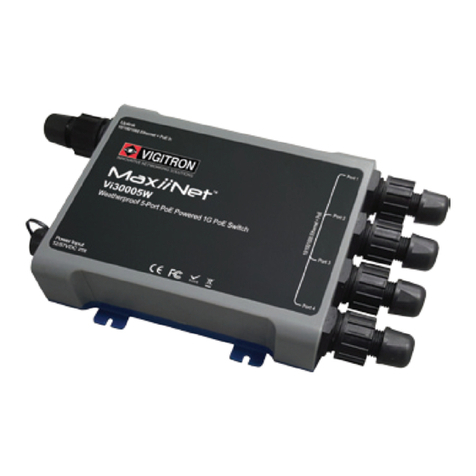
MaxiiNet Vi30005 User manual

MaxiiNet

MaxiiNet Vi30005 User manual

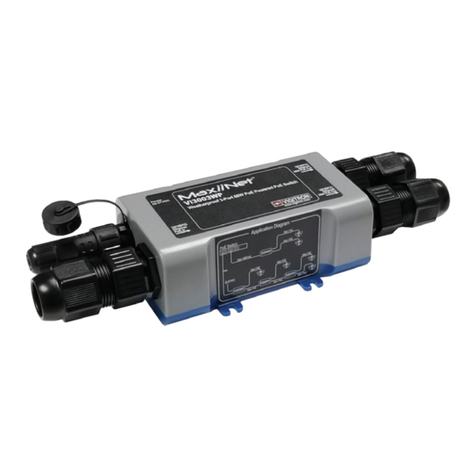
MaxiiNet Vi30005W User manual

MaxiiNet

MaxiiNet Vi30005W User manual

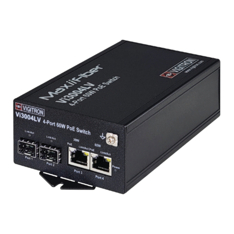
MaxiiNet Vi3004LV User manual

MaxiiNet

MaxiiNet Vi3004LV User manual

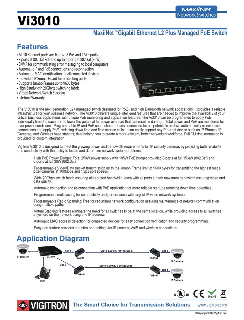
MaxiiNet VI3010 User manual

MaxiiNet

MaxiiNet VI3010 User manual

MaxiiNet Vi30005 User manual

MaxiiNet

MaxiiNet Vi30005 User manual

MaxiiNet Vi3003WP User manual

MaxiiNet

MaxiiNet Vi3003WP User manual

MaxiiNet Vi30103 User manual

MaxiiNet

MaxiiNet Vi30103 User manual

MaxiiNet Vi3103 User manual

MaxiiNet

MaxiiNet Vi3103 User manual

MaxiiNet Vi3103 User manual

MaxiiNet

MaxiiNet Vi3103 User manual

Popular Switch manuals by other brands

FM Systems VLS771-2 installation manual

FM Systems

FM Systems VLS771-2 installation manual

SECO-LARM SLI ENFORCER SD-7623-GSTQ installation manual

SECO-LARM

SECO-LARM SLI ENFORCER SD-7623-GSTQ installation manual

Avaya Cajun P550R Release notes

Avaya

Avaya Cajun P550R Release notes

H3C 6W101 Installation, quick start

H3C

H3C 6W101 Installation, quick start

Freedom9 freeConnect 500 Specifications

Freedom9

Freedom9 freeConnect 500 Specifications

Ruijie RG-EG210G-P quick start guide

Ruijie

Ruijie RG-EG210G-P quick start guide

Lenovo RackSwitch G7052 installation guide

Lenovo

Lenovo RackSwitch G7052 installation guide

Ascentic MH4 Series user manual

Ascentic

Ascentic MH4 Series user manual

Omron WL-N manual

Omron

Omron WL-N manual

Crestron CLW-SLVS1W manual

Crestron

Crestron CLW-SLVS1W manual

Altronics redback A 4480 operating manual

Altronics

Altronics redback A 4480 operating manual

MSTRONIC PSE-SW8G44A4 user manual

MSTRONIC

MSTRONIC PSE-SW8G44A4 user manual

ADC UltraWAVE R4S Specification sheet

ADC

ADC UltraWAVE R4S Specification sheet

GAIM Compact Troubleshooting

GAIM

GAIM Compact Troubleshooting

StarTech.com STARVIEW SV231DDUSB instruction manual

StarTech.com

StarTech.com STARVIEW SV231DDUSB instruction manual

Siemens 3VM9988-0AA1 Series operating instructions

Siemens

Siemens 3VM9988-0AA1 Series operating instructions

Fritz! 7330 Installation and operation

Fritz!

Fritz! 7330 Installation and operation

D-Link DGS-3212SR user guide

D-Link

D-Link DGS-3212SR user guide

manuals.online logo
manuals.online logoBrands
  • About & Mission
  • Contact us
  • Privacy Policy
  • Terms and Conditions

Copyright 2025 Manuals.Online. All Rights Reserved.