_______________________________________________________________ Maxim Integrated Products 1
For pricing, delivery, and ordering information, please contact Maxim Direct at 1-888-629-4642,
or visit Maxim’s website at www.maxim-ic.com.
MAX11835 Evaluation System
Evaluates: MAX11835
General Description
The MAX11835 evaluation system (EV system)
demonstrates a complete solution to drive single and
multilayer piezo actuators to create haptic feedback
for products featuring touch interfaces. The MAX11835
efficiently generates any type of user-programmable
waveforms including sine, trapezoidal, square, and
pulse to drive the piezo loads to create custom haptic
sensation. The low-power device directly interfaces
with an application processor/host controller through an
I2C interface and integrates various blocks including a
boost regulator, pattern storage memory, and waveform
generator in one package, thus providing a complete
haptic feedback controller solution.
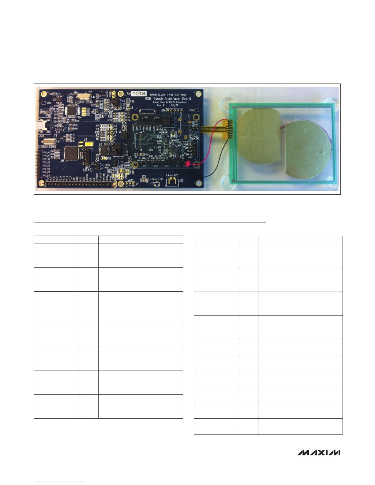
The EV system is a multiboard system that includes a
MAXQ2000 USB touch interface board (UTIB) and a
MAX11835 daughter board.
Note: The CD-ROM included with the EV kit contains
a User’s Guide that provides information about the
graphical user interface (GUI).
Note: The MAX11835 is not a touch-screen control-MAX11835 is not a touch-screen control-
ler and the touch panel is only provided for haptic
feedback purposes, with the 4-wire flex connector left
unconnected.
Features
S Convenient USB Interface
S Touch Panel with Piezo Actuator Mounted for
Haptic Feedback
S Analog Tracking-Mode Capability
S Easy-to-Use WindowsMGraphical User Interface
(GUI) Allows Register Programming for Various
Haptic Waveforms
S All Components Mounted on a Plexiglass Base for
Ease of Handling
S Single-Supply Operation through the USB
S Option for External Power Supply for the Boost
Regulator
S Separate User’s Guide Available for the Graphical
User Interface
Ordering Information
EV System Contents List
+Denotes lead(Pb)-free and RoHS compliant.
Windows and Windows XP are registered trademarks of
Microsoft Corp.
19-5507; Rev 0; 9/10
PART TYPE PC
INTERFACE
INTERFACE
TYPE
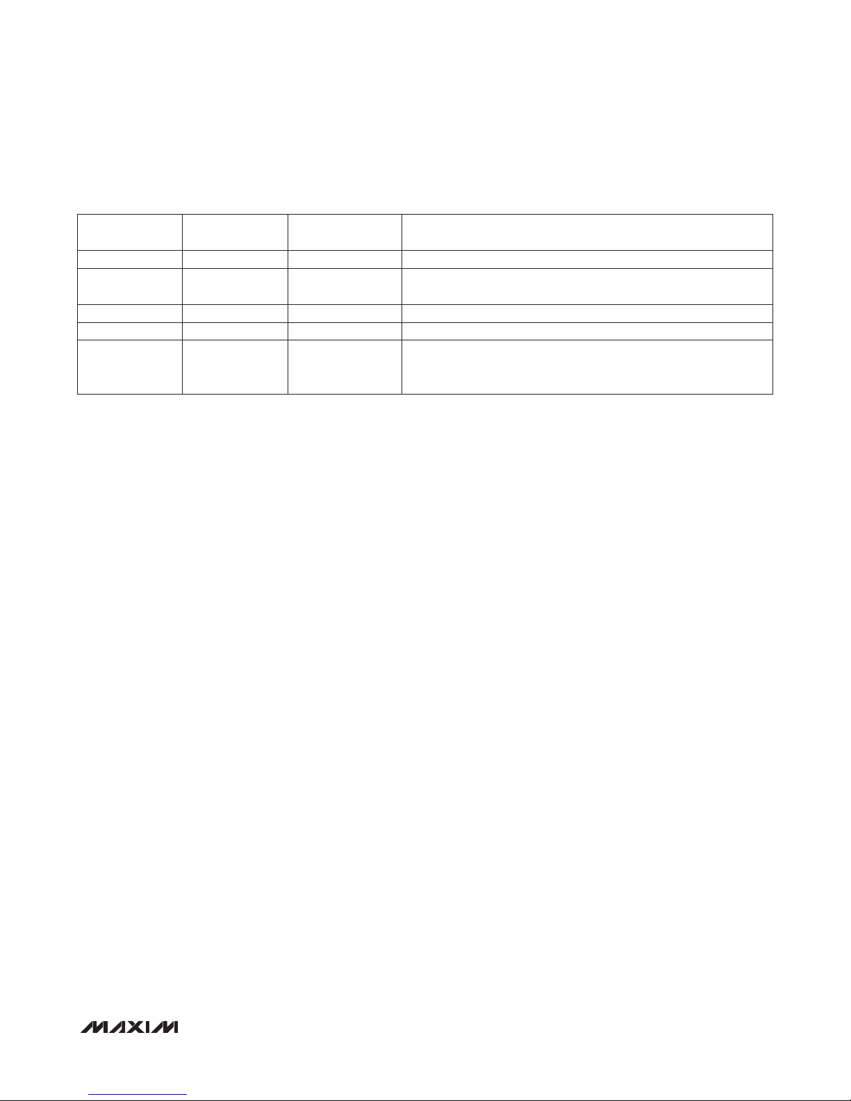
MAX11835TEVS+ EV
System USB Windows
QTY DESCRIPTION
1 CD-ROM containing a USB driver, quick guide, GUI software for Windows XPM, and PCB schematic and layout files
1 USB touch interface board (MAXQ2000 UTIB board)
1 Haptic actuator controller daughter board (MAX11835) with a connector to plug in to the UTIB board
1Piezo driver MAX11835 daughter board with a connector to plug in to the UTIB2 board (included with the haptic
versions only)
1Fujitsu 3.5in touch panel (Fujitsu 817-T010-1401-T670) with piezos mounted under them for haptic feedback
purpose only
2 CUI piezos (Cui Inc. CFT-44TW100-0.6A1-70C) for haptic feedback
1 Mini USB cable