Evaluates: MAX7349/Emulates: MAX7347/MAX7348
most recent scan code is identified in the Key Grid.
Click the 0x04 Configuration group’s Read button
and verify reported status sound from keypress.
10) In the 0x05 Ports group, uncheck the GPO7 box
and click Write. Verify LED2 lights up.
11) In the 0x05 Ports group, check the GPO7 box and
click Write. Verify LED2 no longer lights.
12) Move shunt JU3 and observe the sounder beep in
response to the ALERT pin. Verify register 0x03
Interrupt shows ALERT as the source of interrupt.
Click the 0x04 Configuration group’s Read button
and verify reported status sound from keypress.
13) In the Sounder group, select the sounder com-
mands 125ms and C5 from the drop-down menus,
check the BUF = 0 box, and click Write. Verify the
sounder beeps. Click the 0x04 Configuration
group’s Read button and verify reported status
sound from keypress.
Detailed Description of Software
Connecting to Hardware
The software automatically searches for the MAX7349
EV kit hardware when launched. Once the hardware is
found and connected, the I2C device address is shown
in the upper-left corner.
Autoread
The software automatically reads registers every 2 to 3
seconds if Auto Read 1-7 is checked. This option should
be left unchecked when preparing to write new values.
Registers
Each of the MAX7349 registers is represented on the
software’s main window. See Figure 1. Each register has
its own Read and Write buttons. Clicking Read entire
FIFO now reads register 0x00 repeatedly, until the FIFO
indicates that all keypress events have been read.
Key Grid
Whenever a keypress event is received, the key loca-
tion is shown on the Key Grid. This grid shows eight
rows and up to eight columns. Register 0x01
Debounce / Port Enable determines how many of the
column pins are taken away from the Key Grid and
used for general-purpose outputs.
Interrupt Response
Although the PC software cannot respond to interrupts
with the speed of a true low-level hardware interrupt, the
software does offer flexibility for evaluation. The software
polls the status of the INT output pin every 2 seconds.
The Interrupt Handler Actions checkboxes determine
what action the software takes when INT is active.
History Window
Each register read or write event is recorded in a scrol-
lable text window underneath the interrupt handler actions.
Keyboard Navigation
When you type on the PC keyboard, the system must
know which control should receive the keys. Press the
Tab key to move the keyboard’s focus from one control
to the next. The focused control is indicated by a dotted
outline. Shift+Tab moves the focus to the previously
focused control. Buttons respond to the keyboard’s
spacebar. Some controls respond to the keyboard’s Up
and Down arrow keys. Activate the program’s menu bar
by pressing the F10 key, then press the letter of the
menu item you want. Most menu items have one letter
underlined, indicating their shortcut key.
Detailed Description of Hardware
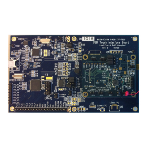
The MAX7349 (U1) scans a matrix of keys (KEY0–KEY55).
The evaluation kit provides a 7 x 8 matrix of keys,
although the MAX7349 is capable of scanning an 8 x 8
matrix. To demonstrate general-purpose output capabili-
ty, one of the scanning columns (COL7/PORT7) is con-
nected to an indicator (LED2).
The FTDI FT232BM (U2) provides the USB engine. The
USB 5V power is regulated down to 2.5V by U3. LED1
indicates that USB 5V power is present.
Jumpers JU4 and JU5 optionally disconnect the
MAX7349 SCL/SDA, allowing the use of an external
user-provided I2C bus. Jumpers JU9 and JU10 option-
ally disable the on-board 1.5kΩtermination resistors R5
and R6, allowing the use of external user-provided I2C
pullup resistors.
To optionally improve the sounder output waveform,
space is provided to mount a MAX4366 (U6) and associ-
ated passive components C31–C35 and R21–R25 to form
a lowpass third-order Chebyshev filter and output stage,
as shown in Figure 12 of the MAX7347/MAX7348/
MAX7349 data sheet. If these filter components are
installed, move JU2 shunt to position 2-3 to use the filter
to drive the on-board pizeo transducer.
The low-voltage RISC microcontroller, MAXQ2000-RAX
(U5), processes commands sent by a program running
on the PC. Each particular EV kit has its own custom
software specific to that kit. Connector P5 is used dur-
ing factory tests to program the MAXQ2000 in-circuit
using the JTAG interface. The connector pin configura-
tion is compatible with the MAXQ2000 evaluation kit’s
MAX7349 Evaluation Kit
4 _______________________________________________________________________________________
