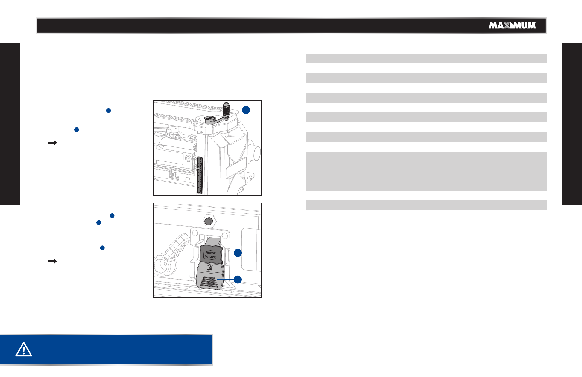
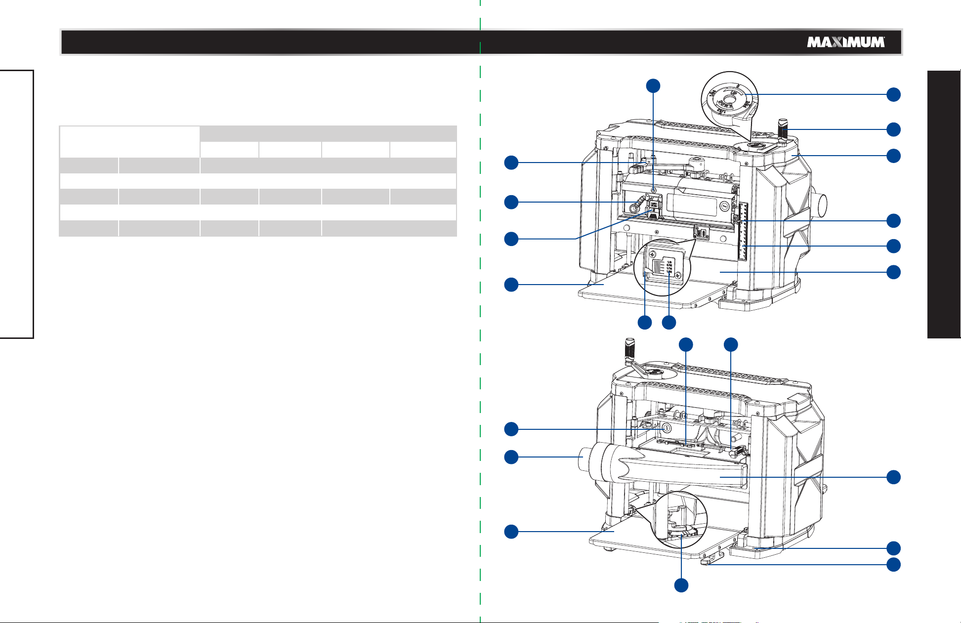
Maximum 055-6971-2 User manual

3
TABLE OF CONTENTS
TABLE OF CONTENTS
Quick start guide
Specifications
Safety guidelines
Know your planer
Assembly
Operation
Maintenance
Troubleshooting
Exploded view
Parts list
Warranty
4
5
6
13
16
25
31
40
42
44
47
SAVE THESE INSTRUCTIONS
This manual contains important safety and operating
instructions. Read all instructions and follow them
when using this product.
NOTE: If any parts are missing or damaged, or if you have any
questions, please call our toll-free helpline at 1-888-670-6682.

5
SPECIFICATIONS
4
QUICK START GUIDE
Motor
Blade speed
Speeds
Number of blades
Cuts/inch (CPI)
Feed speed
Min cutting length
Max cutting width
Cutting depth range
In-feed/out-feed table size
Max depth of cut
Dust port
Weight
120 V, 60 Hz, 15A
10,000 RPM (no load)
2
3
96 & 179
7.9 & 4.2 m/min
5 1/2" (14 cm)
13" (33 cm)
3/16"–6" (0.5–15.2 cm)
13 1/16 x 11 1/4" (33.2 x 28.5 cm)
3" (76 mm) wide stock; 1/8" (3 mm),
6" (150 mm) wide stock; 3/32" (2.4 mm),
9" (228 mm) wide stock; 1/16" (1.6 mm),
13" (330 mm) wide stock; 1/32" (0.8 mm)
4" (10 cm) & 2 1/2" (6.35 cm)
77 lb (35 kg)
SPECIFICATIONS
CAUTION!
• Read and understand the following instructions to get the
best use of the planer planing function.
This planer is designed for professional wood working. This planer finishes rough-cut
lumber to size and planes soft- and hardwoods up to 6" (15.2 cm) thick and 13" (330
cm) wide. DO NOT use under wet conditions or in presence of flammable liquids or
gases. DO NOT let children come into contact with the tool. Supervision is required
when inexperienced operators use this tool.
model no. 055-6971-2 | contact us 1-888-670-6682
To turn your planer on:
• With the switch key inserted
into the switch , lift the switch
to turn it on.
To turn your planer off:
• Press the switch down to turn it
off.
see page 25.
• Turning the cutter head
adjustment handle clockwise
lowers the cutter head. Turning
the cutter head adjustment
handle counter-clockwise raises
the cutter head.
see page 23.
(1)
(2)
2
2
1
2
2
2
2
1

7
SAFETY GUIDELINES
6
SAFETY GUIDELINES
model no. 055-6971-2 | contact us 1-888-670-6682
SAFETY GUIDELINES
This manual contains information that relates to PROTECTING PERSONAL SAFETY and
PREVENTING EQUIPMENT PROBLEMS. It is very important to read this manual carefully
and understand it thoroughly before using the product. The symbols listed below are
used to indicate this information.
Note: The word “Note” is used to inform the reader of something the operator needs to
know about the tool.
SAFETY RECOMMENDATIONS
These precautions are intended for the personal safety of the operator and others
working with the operator. Failure to follow these instructions may result in a
permanent loss of vision, serious personal or even fatal injury, property damage and/or
tool damage.
Please take time to read and understand these instructions.
Safety is a combination of common sense, staying alert and knowing how your planer
works.
GENERAL POWER TOOL SAFETY WARNINGS
SAVE ALL WARNINGS AND INSTRUCTIONS FOR FUTURE REFERENCE
The term “power tool” in the warnings refers to your mains-operated (corded) power
tool.
GENERAL SAFETY INSTRUCTIONS
•KEEP GUARDS IN PLACE and in working order.
•REMOVE ADJUSTING KEYS AND WRENCHES. Form a habit of checking to see that
keys and adjusting wrenches are removed from tool before turning it on.
•KEEP WORK AREA CLEAN. Cluttered areas and benches invite injuries.
•DON’T USE IN DANGEROUS ENVIRONMENT. Don’t use power tools in damp or wet
locations, or expose them to rain. Keep work area well lighted. Always operate tool in
a well-ventilated area free of combustible materials, gasoline or solvent vapours. If
sparks come in contact with flammable vapours, they may ignite, causing fire or
explosion.
•KEEP CHILDREN AWAY. All visitors should be kept a safe distance from work area.
•MAKE WORKSHOP KID-PROOF with padlocks, master switches, or by removing starter
keys.
•DON’T FORCE TOOL. It will do the job better and safer at the rate for which it was
designed.
•USE RIGHT TOOL. Don’t force tool or attachment to do a job for which it was not
designed.
•USE PROPER EXTENSION CORD. Make sure your extension cord is in good condition.
When using an extension cord, be sure to use one heavy enough to carry the current
your product will draw. An undersized cord will cause a drop in line voltage resulting
in overheating and loss of power. The Recommended size for extension cords shows
the correct size to use depending on cord length and nameplate ampere rating. If in
doubt, use the next heavier gauge. The smaller the gauge number, the heavier the
cord. When operating a power tool outside, use an outdoor extension cord marked
“W-A” or “W.” These cords are rated for outdoor use and reduce the risk of electric
shock.
•WEAR PROPER APPAREL. Do not wear loose clothing, gloves, neckties, rings,
bracelets, or other jewellery which may get caught in moving parts. Nonslip footwear
is recommended. Wear protective hair covering to contain long hair. Air vents often
cover moving parts and should also be avoided.
•ALWAYS USE SAFETY GLASSES. Also use face or dust mask if cutting operation is
dusty. Everyday eyeglasses only have impact resistant lenses; they are not safety
glasses.
•SECURE WORK. Use clamps or a vise to hold work when practical. It’s safer than using
your hands and it frees both hands to operate tool.
•DON’T OVERREACH. Keep proper footing and balance at all times.
•MAINTAIN TOOLS WITH CARE. Keep tools sharp and clean for best and safest
performance. Follow instructions for lubricating and changing accessories.
•DISCONNECT TOOLS before servicing and when changing accessories, such as blades,
bits, cutters, and the like.
•REDUCE THE RISK OF UNINTENTIONAL STARTING. Make sure switch is in off position
before plugging in.
•USE RECOMMENDED ACCESSORIES. Consult the instruction manual for recommended
accessories. The use of improper accessories may cause risk of injury to persons.
•NEVER STAND ON TOOL. Serious injury could occur if the tool is tipped or if the
cutting tool is unintentionally contacted.
•CHECK DAMAGED PARTS. Before further use of the tool, a guard or other part that is
damaged should be carefully checked to determine that it will operate properly and
perform its intended function—check for alignment of moving parts, binding of moving
parts, breakage of parts, mounting, and any other conditions that may affect its
operation. A guard or other part that is damaged should be properly repaired or
replaced.
•DIRECTION OF FEED. Feed work into planer according to direction of feed arrows on
top of the unit.
DANGER!
Potential hazard that will result in serious injury or loss of life.
WARNING!
Potential hazard that could result in serious injury or loss of life.
CAUTION!
Potential hazard that may result in moderate injury or damage to equipment.
WARNING!
Read all safety warnings, instructions, illustrations and specifications provided
with this power tool. Failure to follow all instructions listed below may result in
electric shock, fire and/or serious injury.

9
SAFETY GUIDELINES
8
SAFETY GUIDELINES
model no. 055-6971-2 | contact us 1-888-670-6682
•NEVER LEAVE TOOL RUNNING UNATTENDED. TURN POWER OFF. Don’t leave tool
until it comes to a complete stop.
SAFETY RULES FOR SURFACE PLANERS
USE SAFETY GOGGLES AND EAR PROTECTION:
ALWAYS WEAR EYE PROTECTION THAT CONFORMS WITH CUL
REQUIREMENTS. FLYING DEBRIS can cause permanent eye damage. Also
use face or dust mask if cutting operation is dusty. Everyday eyeglasses
only have impact resistant lenses; they are NOT safety glasses.
•Do not operate this machine until it is completely assembled and installed according
to the instructions. A machine incorrectly assembled can cause serious injury.
•Obtain advice from your supervisor, instructor, or another qualified person if you are
not thoroughly familiar with the operation of this machine. Knowledge is safety.
•Follow all wiring codes and recommended electrical connections to prevent shock or
electrocution.
•Keep knives sharp and free from rust and pitch. Dull or rusted knives work harder and
can cause kickback.
•Never turn the machine "ON" before clearing the table of all objects (tools, scraps of
wood, etc.). Flying debris can cause serious injury.
•Never turn the machine "ON" with the workpiece contacting the cutterhead. Kickback
can occur.
•Secure the machine to a supporting surface to prevent the machine from sliding,
walking or tipping over.
•Be sure that the cutter knives are mounted as described in the instruction manual and
check that all bolts are firmly tightened before connecting unit to power source.
•Avoid awkward operations and hand positions. A sudden slip could cause a hand to
move into the knives.
•Keep arms, hands, and fingers away from the cutterhead, the chip exhaust opening,
and the feed rollers to prevent severe cuts.
•Never reach into the cutterhead area while the machine is running. Your hands can be
drawn into the knives.
•Do not stand in line with the workpiece. Kickback can cause injury.
•Allow the cutterhead to reach full speed before feeding a workpiece. Changing
speeds while planing can cause kickback.
•When planing bowed stock, place the concave (cup down) side of the stock on the
table and cut with the grain to prevent kickback.
•Do not feed a workpiece that is warped, contains knots, or is embedded with foreign
objects (nails, staples, etc.). Kickback can occur.
•Do not feed a short, thin, or narrow workpiece into the machine. Your hands can be
drawn into the knives and/or the workpiece can be thrown at high speeds. See the
Operation section of this instruction manual for details.
•Do not feed a workpiece into the outfeed end of the machine. The workpiece will be
thrown out of the opposite side at high speeds.
•Remove shavings only with the power "OFF" and the cutterhead stopped to prevent
serious injury.
•Properly support long or wide work pieces. Loss of control of the workpiece can
cause serious injury.
•Never perform layout, assembly or set-up work on the table/work area when the
machine is running. Serious injury will result.
•Turn the machine "OFF", disconnect it from the power source, and clean the
table/work area before leaving the machine. Lock the switch in the "OFF" position to
prevent unauthorized use. Someone else might accidentally start the machine and
cause injury to themselves or others.
SUPPLEMENTAL SAFETY RULES FOR PLANERS
• To avoid injury, never rotate the cutterhead directly with your hands.
• Keep hands away from the underside of the cutterhead carriage.
• Never clear clogs, make cutter knife replacement, or any other repairs/adjustments
with unit plugged in.
• Make certain that the switch is in the "OFF" position before connecting plug to a
power source.
• Stay alert—never operate the unit when tired or under the influence of drugs, alcohol,
or medication.
• Do not use in dangerous environments. Do not use near flammable substances, in
damp or wet locations, or exposed to rain.
• Never plane material which is shorter than 5 1/2" (140 mm) narrower than 3/4" (19.05
mm), or wider than 13" (330 mm).
• Exhaust chute: remove shavings with brush or vacuum after power has been shut off
and cutterhead has stopped rotating.
• Always locate planer with proper clearance on the outfeed side of the unit to prevent
pinching or binding of the workpiece against any obstacle.
• Maintain the proper relationships of infeed and outfeed table surfaces and cutterhead
knife path.
• Lock the speed setting securely before feeding the workpiece through the machine.
Changing speeds while planing can cause kickback.
ADDITIONAL SAFETY INFORMATION
WARNING!
Failure to follow these rules may result in serious personal injury.
WARNING!
Never modify the power tool or any part of it. Damage or personal injury could
result.

11
SAFETY GUIDELINES
10
SAFETY GUIDELINES
ELECTRICAL SAFETY
GROUNDING INSTRUCTIONS:
In the event of a malfunction or breakdown, grounding provides a path of least
resistance for electric current to reduce the risk of electric shock. This tool is equipped
with an electric cord having an equipment-grounding conductor and a grounding plug.
The plug must be plugged into a matching outlet that is properly installed and
grounded in accordance with all local codes and ordinances.
Do not modify the plug provided. If it will not fit the
outlet, have the proper outlet installed by a
qualified electrician. Improper connection of the
equipment-grounding conductor can result in a risk
of electric shock. The conductor with a green outer
surface, with or without yellow stripes, is the
equipment-grounding conductor. If repair or
replacement of the electric cord or plug is
necessary, do not connect the equipment-grounding
conductor to a live terminal.
Check with a qualified electrician or service
technician if the grounding instructions are not
completely understood, or if in doubt as to whether
the tool is properly grounded. Use only three-wire
extension cords that have three-prong grounding plugs and three-pole receptacles that
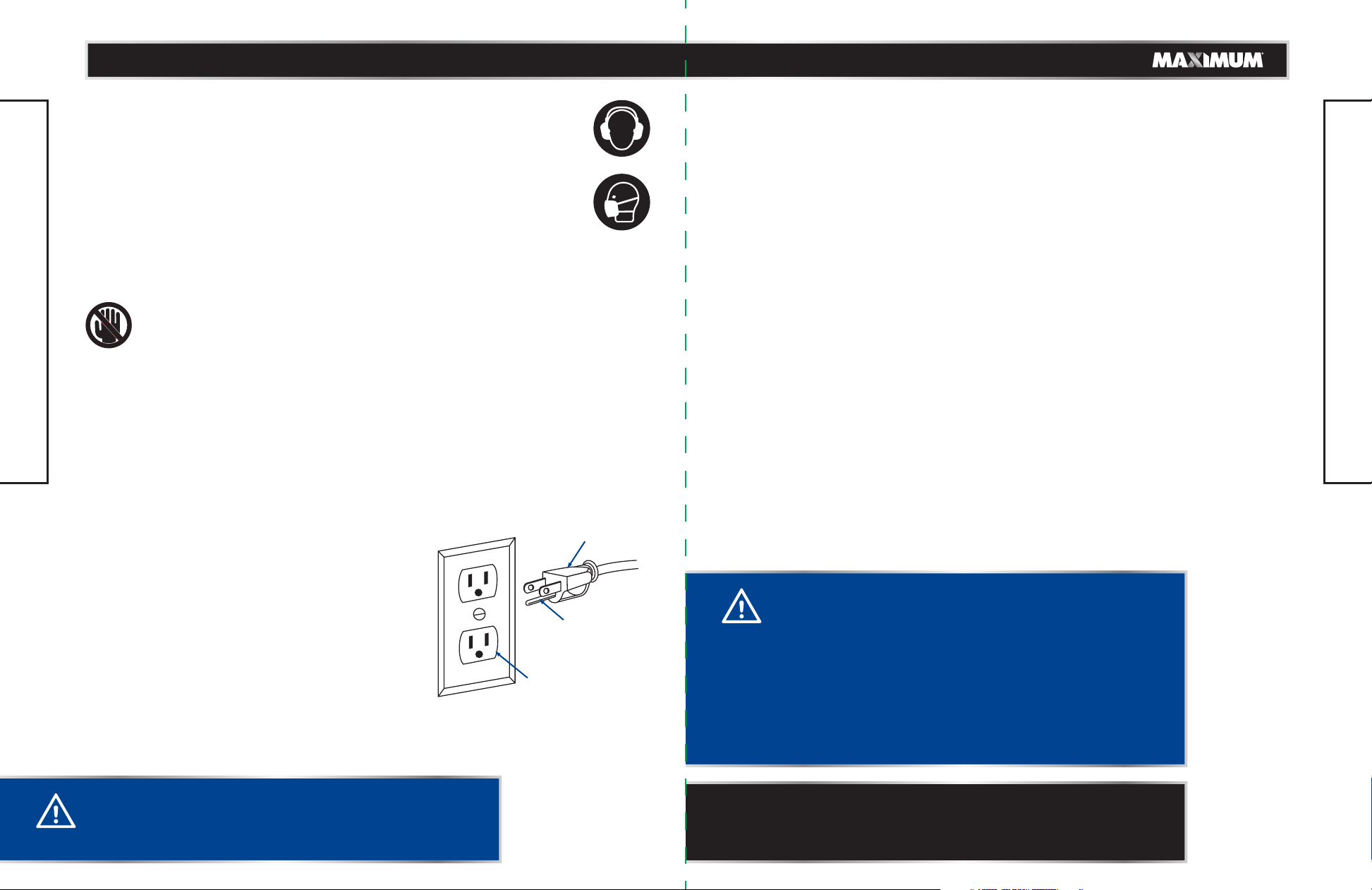
accept the tool's plug, as shown in Fig. 1. Repair or replace a damaged or worn cord
immediately.
GUIDELINES FOR USING EXTENSION CORDS:
• Make sure the extension cord is in good condition. When using an extension cord, be
sure to use one that is heavy enough to carry the current that your product will draw.
An undersized cord will cause a drop in line voltage, which will result in loss of power
and overheating. The table on the next page shows the correct size to be used
according to cord length and nameplate ampere rating. When in doubt, use the next
heavier gauge. The smaller the gauge number, the heavier the cord.
• Make sure your extension cord is properly wired and in good condition. Always
replace a damaged extension cord, or have it repaired by a qualified person before
using it. Protect your extension cords from sharp objects, excessive heat, and damp or
wet areas.
• Use a separate electrical circuit for your tools. This circuit must consist of not less than
#12 wire with a 20 A time-delayed fuse or a #14 wire with a 15 A time-delayed fuse.
Before connecting the motor to the power line, make sure the switch is in the OFF
position and the electric current is rated the same as the current stamped on the
motor nameplate. Running at a lower voltage will damage the motor.
• Use only extension cords that are intended for outdoor use. These extension cords are
identified by a marking "Acceptable for use with outdoor appliances; store indoors
while not in use." Use only extension cords having an electrical rating not less than the
rating of the product. Do not use damaged extension cords. Examine extension cord
before using and replace if damaged. Do not abuse extension cords and do not yank
on any cord to disconnect. Keep cord away from heat and sharp edges. Always
disconnect the extension cord from the receptacle before disconnecting the product
from the extension cord.
• WARNING – To reduce the risk of electrocution, keep all connections dry and off the
ground. Do not touch plug with wet hands.
CAUTION!
In all cases, verify that the outlet in question is properly
grounded. if you are not sure, have a licensed electrician
check the outlet.
WARNING!
• Use the proper extension cord. Make sure to use an
extension cord that is heavy enough to carry the current
required by the tool. An undersized cord will cause a
drop in line voltage, resulting in loss of power and
overheating of the tool.
• Use the extension cord only for intended purpose. Do
not pull the extension cord to remove it from the power
socket.
• This tool must be grounded while in use in order to
protect the operator from electric shock.
Fig. 1
Three-prong plug
Grounding prong
Properly grounded
outlet
NOTE: Recycle unwanted materials rather than disposing of
them as waste. Sort the tool and its components in specific
categories and take to the local recycling centre or dispose of
them in an environmentally safe way.
Danger! Keep hands away from blade.
model no. 055-6971-2 | contact us 1-888-670-6682
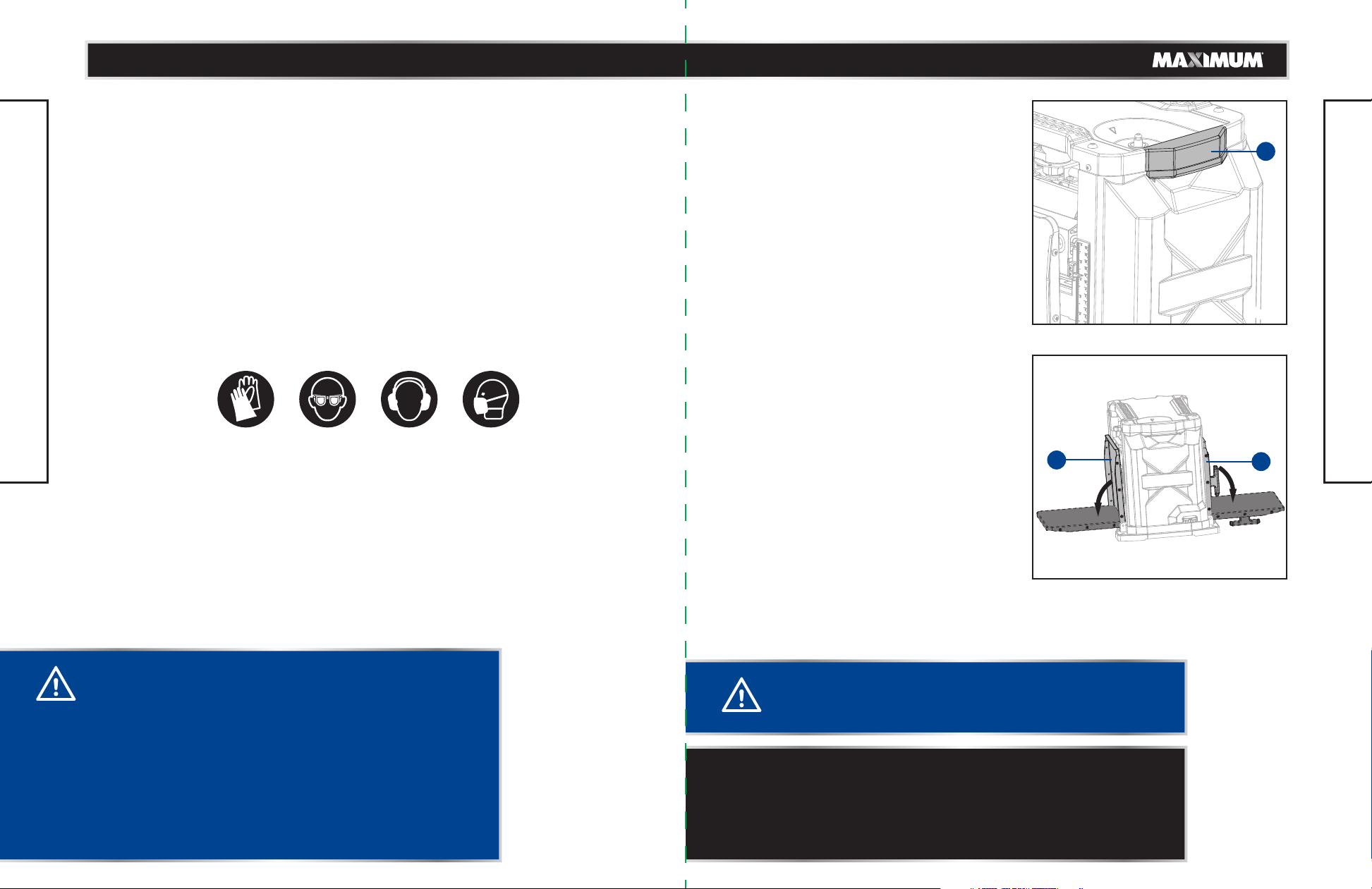
The tool is loud and the sound can cause hearing damage. Always wear
ear protection to help prevent hearing damage and loss. Failure to comply
may result in moderate injury.
USE DUST MASK:
Some dust created by sawing contains chemicals that are known to cause
cancer, birth defects or other reproductive harm. Some examples of these
chemicals come from lead-based paints; crystalline silica from bricks,
cement and other masonry products; and arsenic and chromium from
chemically treated lumber. To reduce exposure to these chemicals, work
in a well-ventilated area with approved safety equipment, such as dust
masks that are specially designed to filter out microscopic particles.

KNOW YOUR PLANER
SAFETY GUIDELINES
1312
AMPERAGE RATING OF THE TOOL
(120 V CIRCUIT ONLY)
MORE THAN
0
6
10
12
NOT MORE THAN
6
10
12
16
25' (7.6 m)
18
18
16
14
50' (15.2 m)
16
16
16
12
100' (30.5 m)
16
14
14
Not recommended
150' (45.7 m)
14
12
12
TOTAL LENGTH OF THE EXTENSION CORD
MINIMUM GAUGE FOR THE EXTENSION CORD (AWG) 21
22
1514
17 16
10
20
18
12
11
13
19
2
3
1
4
5
6
9
8
7
• Ground Fault Circuit Interrupter (GFCI) protection should be provided on the circuit(s)
or outlet (s) to be used for the planer. Receptacles are available having built-in GFCI
protection and may be used for this measure of safety.
Recommended size for extension cords
model no. 055-6971-2 | contact us 1-888-670-6682

KNOW YOUR PLANER
KNOW YOUR PLANER
1514
No.
1
2
3
4
5
6
7
8
9
10
11
Description
Adjustable scale
Cutter head adjustment handle
Carrying handle
Depth scale pointer
Depth scale
Table
Dust chute
Mounting hole
Plug cable storage
Turret stop
Out-feed extension table
No.
12
13
14
15
16
17
18
19
20
21
22
Description
Dust port
Carbon brush cap
Open-end wrench
T-wrench
Material removal depth scale
Material removal depth pointer
In-feed extension table
On/Off switch
Two-speed knob
Carriage lock lever
Overload protector/reset button
The safe use of this product requires an understanding of the information on the tool
and in this operator’s manual as well as a knowledge of the project you are attemping.
Before use of this product, familiarize yourself with all operating features and safety
rules.
15 AMP MOTOR
The planer has a powerful 15 amp motor with sufficient power to handle tough cutting
jobs.
TOOL STORAGE
The open-end wrench and T-wrench can be stored in tool tray located on the top back
side of the planer.
TURRET STOP
The turret stop, located on the right side of the planer, has preset measurements for
repetitive planing.
MATERIAL REMOVAL DEPTH SCALE
The material removal depth scale is located on the front of your planer and measures
depth of cuts up to 1/8".
DUST PORT
Attaching a 2 1/2" shop vac hose to the dust port helps minimize sawdust accumulation
on the workpiece.
OVERLOAD PROTECTOR/RESET BUTTON
Used to reset the tool after the overload protection has been activated.
CUTTER HEAD ADJUSTMENT HANDLE
The cutter head adjustment handle is used to raise and lower the cutter head assembly.
Lower the cutter head assembly by turning it counter-clockwise and raise the cutter
head assembly by turning it clockwise.
DEPTH SCALE
The depth scale accurately displays the height of the cutter head assembly. It helps to
set the cutting depth.
IN-FEED EXTENSION TABLE
Used to support the workpieces before being picked up.
OUT-FEED EXTENSION TABLE
Used to support the workpieces after they have passed under the cutter knives.
TABLE
Supports the workpieces during a cutting operation with a combination of in-feed and
out-feed table surfaces.
CARRYING HANDLE
For balancing purposes when carrying or transporting the planer from one place to
another, a carrying handle is provided on each side of the cover.
model no. 055-6971-2 | contact us 1-888-670-6682

No. Description Qty. Illustration
Planer assembly1
Dust chute
Dust port
2
3
Cutter head adjustment handle
with flower pan head screw
M6 x 16
4
Open-end wrench5
T-wrench6
1
1
1
1
1
1
1716
ASSEMBLY
ASSEMBLY
UNPACKING
Carefully lift planer from the carton by the carrying handles on each side of the side
cover, and place it on a level work surface. Inspect the unit for damage. If the unit has
been damaged in transit, contact the carrier and complete a damage claim. Do this
immediately because there is a time limitation for damage claims.
Do not use this product if any parts of the package contents are already assembled to
your product when you unpack it. Package contents are not assembled to the product
by the manufacturer and require customer installation. Use of a product that may have
been improperly assembled could result in serious personal injury.
This tool is heavy. For your own safety, it is recommended that two people
lift this machine from the carton or serious injury could result.
The in-feed and out-feed extension tables are attached to the planer. Shipped
in a folded, “upright” position, the extension table must be in the “down” position
before planing can begin.
• Inspect the tool carefully to make sure no breakage or damage occurred during
shipping.
• Do not discard the packing material until you have carefully inspected and
satisfactorily operated the tool.
• If any parts are damaged or missing, please call 1-888-670-6682 for assistance.
WARNING!
If any parts are damaged or missing do not operate this
tool until the parts are replaced. Use of this product with
damaged or missing parts could result in serious personal
injury.
• Do not attempt to modify this tool or create accessories
not recommended for use with this tool. Any such
alteration or modification is misuse and could result in a
hazardous condition leading to possible serious personal
injury.
• Do not connect to power supply until assembly is
complete. Failure to comply could result in accidental
starting and possible serious personal injury.
• Risk of injury! Always pull out the mains plug
(disconnect the product from its power supply) before
commencing work on the product.
model no. 055-6971-2 | contact us 1-888-670-6682
Screwdriver
TOOLS NEEDED FOR ASSEMBLY
Wrench

18 19
ASSEMBLY
ASSEMBLY
BEFORE YOUR START
This MAXMIUM 13" (330 cm) planer finishes rough-cut lumber to size and planes soft-
and hardwoods up to 6" (15.2 cm) thick and 13" (330 cm) wide.
Any piece of wood will have a natural tendency to bow and warp, even if it was initially
milled perfectly straight. This planer features a powerful 15 A motor with overload
protection and high carbon steel knives to handle such tough cutting jobs. Intended for
use by the Do-It-Yourself enthusiast, for wood working projects at home and in the
workshop.
This tool is intended for:
This planer is designed for wood working:
• Surface planing (smoothing rough lumber)
• Thickness planing (reducing the thickness of a board)
DO NOT use under wet conditions or in presence of flammable liquids or gases.
DO NOT let children come into contact with the tool. Supervision is required when
inexperienced operators use this tool.
But even the best guard will not make up for poor judgment, carelessness or
inattention.
ALWAYS USE COMON SENSE AND EXERCISE CAUTION!
EXTENSION TABLES (Fig. 3)
Before using your planer, fold down the
in-feed extension table (1) in the front and
out-feed extension table (2) back of the tool.
After extended use, the extension tables may
be slightly out of level. See LEVELLING THE
TABLE EXTENSIONS in the Maintenance
section of this manual.
TRANSPORTING THE PLANER (Fig. 2)
When moving your planer, carry it by the side
carrying handles (1) of the planer.
CAUTION!
• Woodworking can be dangerous if safe and proper
operating procedures are not followed. As with all power
tools, there are certain hazards involved with the
operation of the product. Using the tool with respect
and caution will considerably lessen the possibility of
personal injury. However, if normal safety precautions
are overlooked or ignored, personal injury to the
operator may result.
• Safety equipment such as guards, push sticks, hold-downs,
featherboards, goggles, dust masks and hearing
protection can reduce your potential for injury.
WARNING!
For your own safety, it is recommended that two people
carry this machine or serious injury could result.
NOTE: The outside edges of the extension tables are level with
the base while the inside edges (closest to the cutterhead) are
below the edge of the base. This is set at the factory to reduce
unnecessary friction between the material and the table while
providing adequate support at the two points (those farthest from
the cutterhead) on the tables that are integral to snipe prevention.
model no. 055-6971-2 | contact us 1-888-670-6682
1
1
2
Fig. 3
Fig. 2Fig. 2

20 21
ASSEMBLY
ASSEMBLY
INSTALLING THE DUST CHUTE
(Fig. 6a–6d)
Loosen Screws
• Using the T-wrench (included), loosen the
three marked screws (1) located at the rear
of the cutter head assembly and do not
remove them.
Align Notches with Screws
• Align the three notches (2) on the dust chute
(3) to the three loosened screws (1).
Align Slots with Hooks
• Align the three slots (4) with the three hooks
(5) on the machine. If the dust chute is a
little deformed, it may be necessary to use
some pressure to ensure that the slots and
hooks match properly.
BENCH MOUNTING (Fig. 4)
To facilitate bench mounting, two different
sized holes (1, 2) are provided on the four
corners of your planer. If mounting the planer
with bolts, use the larger holes. If mounting
the planer with nails or screws, use the smaller
holes. It is not necessary to use both sets of
holes.
Always mount your planer firmly to prevent
movement. To enhance the tool’s portability, it
can be mounted to a piece of 1/2" (12.7 mm)
or thicker plywood which can then be clamped
to your work support or moved to other job
sites and reclamped.
INSTALLING THE CUTTER HEAD
ADJUSTMENT HANDLE (Fig. 5)
• Attach the cutter head adjustment handle (1)
to the planer and fasten with screw M6 x 16
(2).
• Tighten the flower pan head screw M6 x 16
(2). using the T-wrench (included).
CAUTION!
The mounting surface should not be warped or otherwise
uneven.
WARNING!
Chips are ejected at significant velocity. Keep hands and
face clear of dust chute and dust port.
WARNING!
Do not operate your planer without dust chute and dust
port in place. Do not insert anything into the dust chute
and dust port unless the planer is unplugged and you are
clearing a clog or obstruction in the unit. Do not get your
face or eyes near the dust chute and dust port when the
planer is in operation. Serious injury could result.
NOTE: If you elect to mount your planer onto a piece of
plywood, make sure that the mounting screws don’t protrude
from the bottom of the wood. The plywood must sit flush on the
work support.
model no. 055-6971-2 | contact us 1-888-670-6682
1
1
5
2
3 3
4
2
2
1
Fig. 6aFig. 4
Fig. 5Fig. 5
Fig. 6a
Fig. 6b

ASSEMBLY
ASSEMBLY
2322
DEPTH ADJUSTMENT (Fig. 8)
Depth Scale
• The depth scale (1), located on the right
front of your planer, indicates the finished
thickness of your workpiece. One rotation of
the cutter head adjustment handle is equal
to 1/16" (1.6 mm); one half rotation is equal
to 1/32" (0.8 mm), etc.
Cutter Head Adjustment Handle
• Turning the cutter head adjustment handle
(2) clockwise lowers the cutter head. Turning
the cutter head adjustment handle (2)
counter-clockwise raises the cutter head.
FINE ADJUSTMENTS (Fig. 8)
The cutter head adjustment handle (2) allows for fine adjustments, from 1/64" (0.4 mm)
to 1/16" (1.6 mm). Fine adjustments are ideal for “shaving” small amounts from your
material. For example, if your planed workpiece measures 3-1/16" (77.8 mm) thick, but
should be 3" (76.2 mm) thick, adjust your planer to remove the excess 1/16" (1.6 mm) as
follows:
• Plane and measure your workpiece. In this example, the starting thickness is 3-1/16"
(77.8 mm).
• Turn the circular label on the cutter head adjustment handle (1) until the “0” mark
aligns with the arrow on the top of the tool. Do not make any other adjustments to the
planer.
• Turn the cutter head adjustment handle (1) clockwise until the 1/16" (1.6 mm) mark
aligns with the arrow.
• Plane your workpiece. The final thickness should be 3" (76.2 mm).
NOTE: Never adjust cutter head height with the cutter head in
the locked position.
Tighten Screws
• Tighten the three screws (1) that secure the
dust chute (3) to the rear of the cutter head
assembly.
Attach Dust Port
• Attach the dust port (6) to the dust chute
(3).
• Attach dust port (6) to a dust collector.
Refer to dust collector owner's manual for
correct procedure and safety information.
CARRIAGE LOCK LEVER (Fig. 7)
• Never adjust the cutter head assembly with
the cutter head lock in the “locked” position.
A complete rotation of the cutter head
adjustment handle moves the cutter head
assembly 1/16" (1.6 mm).
To Raise The Cutter Head
• With the power switch in the OFF ( O )
position, turn the carriage lock lever (1)
counter-clockwise to unlock the cutter head
assembly.
• Turn the cutter head adjustment handle
clockwise to raise the cutter head.
• Once cutter head is in the desired position,
lock the cutter head by turning the carriage
lock lever (1) clockwise.
To Lower The Cutter Head
• With the power switch in the OFF ( O )
position, turn the carriage lock lever (1)
counter-clockwise to unlock the cutter head
assembly.
• Turn the cutter head adjustment handle
counter-clockwise to lower the cutter head.
• Once cutter head is in the desired
position, lock the cutter head by turning the
carriage lock lever (1) clockwise. To unlock
To lock To unlockTo lock
model no. 055-6971-2 | contact us 1-888-670-6682
3
3
6
1
2
Fig. 8
1
5
1
Fig. 12
Fig. 6d
Fig. 6cFig. 6c
Fig. 6d
Fig. 7Fig. 7

ON/OFF SWITCH (Fig. 10)
This planer is equipped with a switch assembly
that has a built-in locking feature. This feature
is intended to prevent unauthorized and
possibly hazardous use by children and others.
To turn your planer on:
• With the switch key (1) inserted into the
switch (2), lift the switch to turn it on.
To turn your planer off:
• Press the switch (2) down to turn it off.
TO SET THE MINIMUM DEPTH TO WHICH THE CARRIAGE CAN TRAVEL WITH
THE TURRET STOP
• Be sure the carriage is set above 1–1/4" (32 mm) before trying to set the turret stop.
• Turn the turret stop until the desired thickness setting shows.
• Unlock the carriage lock lever and lower the carriage.
• Plane the workpiece at desired increments until the correct final thickness is achieved.
NOTE: Do not use force to crank the carriage below the level
that the turret stop indicates. Permanent damage to the height
adjustment system on your planer will result.
OPERATION
ASSEMBLY
2524
TURRET STOP (Fig. 9)
• Your planer is equipped with a turret stop (1) ,
for planing multiple boards to the same
pre-set depth. Stops are set at 0", 1/4" (6.4
mm), 1/2" (12.7 mm), 3/4" (19 mm), 1" (25.4
mm) and 1-1/4" (32 mm).
WARNING!
Always remove the switch key when the tool is not in use,
and keep the switch key in a safe place. In the event of a
power failure, turn the switch off and remove the key. This
action will prevent the tool from accidentally starting
when the power returns.
model no. 055-6971-2 | contact us 1-888-670-6682
1
2
1
Fig. 10
3
WARNING!
To reduce the risk of serious personal injury, turn unit off and disconnect it from
power source before making any adjustments or removing/installing
attachments or accessories. An accidental start-up can cause injury.
WARNING!
Do not allow familiarity with tools to make you careless. Remember that a
careless fraction of a second is sufficient to inflict serious injury.
WARNING!
Always wear eye protection that conforms with CUL requirements. Failure to do
so could result in objects being thrown into your eyes, resulting in possible
serious injury.
WARNING!
Do not use any attachments or accessories not recommended by the
manufacturer of this tool. The use of attachments or accessories not
recommended can result in serious personal injury.
WARNING!
The use of this planer on materials not listed could damage the planer and could
cause serious personal injury.
WARNING!
Never plane workpiece with loose knots or foreign objects. Do not plane
workpieces that are severely bowed, twisted, or knotted. Cutter blades can dull,
chip, or break causing possible serious personal injury.
WARNING!
Do not force feed the workpiece through the machine. Let the planer apply the
proper feed rate.
Fig. 12Fig. 9

1
FINISHING
179 CUTS
PER INCH
DIMENSIONING
96 CUTS
PER INCH
2
SHIFT ONLY WHILE
MACHINE IS RUNNING
To lock your planer:
• Press the switch (2) down. Remove the switch key (1) from the switch, and store it in a
safe, secure location.
OVERLOAD PROTECTOR/RESET BUTTON (Fig. 10)
This planer is equipped with an overload protector/reset button (3) which will
automatically “trip” and cause the planer to shut down if the motor is overloaded due to
continuous heavy cutting.
The planer overload protector can only be reset manually by the user after the planer
has been allowed to adequately cool. Allow 15–30 minutes.
Should the overload protector “trip”:
• Turn switch off (O).
• Raise carriage and remove board.
• After 15–30 minutes, reset overload protector by pushing the reset button on the top
of the motor housing. An audible click will indicate the overload protector is reset.
Once the button is reset, the tool may be started and operated as normal.
• If motor has cooled, button will remain in. TO USE THE MATERIAL REMOVAL DEPTH SCALE
• Slide approximately 3" (76 mm) of your material under the middle of the carriage.
• Be sure the wood is lying flat against the base of the planer. If the material is inserted
at an angle, the reading may be inaccurate.
• Crank the carriage down on the material until the material removal bar engages the
wood. You will see the red arrow begin to move up the scale indicating the amount of
material to be removed with the carriage at that height.
• Adjust the carriage height until the desired depth of cut appears on the scale.
• Pull the material out from under the carriage.
• Turn the unit on and feed your material into the cutterhead.
NOTE: If the button won’t click into place immediately, the
motor is still too hot and must be allowed to cool.
NOTE: When planing particularly hard or figured species of
wood, speed “1” is recommended. The slower feed rate will reduce
knife wear and tear-out by delivering 179 cuts per inch to the
material.
NOTE: Do not exceed the recommended depth of cut for various
widths of material recommended on the material removal gauge
(Table A).
NOTE: Only switch speeds when the planer is running.
OPERATION
OPERATION
2726
SPEED SELECTION (Fig. 11)
Your planer has the ability to feed material at
two different speeds. The two-speed knob (1)
was designed to improve efficiency when
planing and to provide the best possible
surface finish to a variety of materials.
To remove material thickness more quickly,
set the unit at speed “2”. This setting delivers
96 cuts per inch to the material.
For finishing, set the unit to speed “1”. Speed
“1” is ideal for ensuring the finest finish on the
last pass before your final thickness is
achieved.
MATERIAL REMOVAL DEPTH SCALE
(Fig. 12)
Your planer is equipped with a material
removal gauge (1) . It is used to indicate the
amount of wood that will be removed in one
pass with the carriage set at its current height.
WARNING!
DO NOT switch the unit on with the material positioned
under the carriage. Serious injury could result.
TABLE A
MATERIAL
REMOVAL
GAUGE
WIDTH
3"
1/32"
1/16"
1/8"
3/32"
0
6" 9" 13"
DEPTH
OF CUT
model no. 055-6971-2 | contact us 1-888-670-6682
1
Fig. 11
Fig. 12
Fig. 11

NOTE: Flip the board back and forth between each pass.
WARNING!
Do not place your body between the rear of the planer
and a stationary object while material is feeding. Serious
injury could result.
WARNING!
Twisted wood may jam your planer. If a jam occurs, turn
the power off, disconnect the power supply and raise the
carriage to release the material from the cutterhead.
WARNING!
Plane only wood that is free from foreign objects, with no
loose knots and as few tight knots as possible. Do not
plane wood that is severely warped, twisted, knotted or
bowed.
WARNING!
DO NOT turn the unit on with the material already
inserted under the carriage. Wait until the rollers and
cutterhead are up to full speed before feeding your
material into the machine.
PLANING BASICS
PROPER PLANING TECHNIQUE
TO PLANE YOUR MATERIAL
• Lower the carriage to the desired height for your first pass.
• Turn the unit on and feed the material into the feed rollers.
• Examine the finished cut and adjust the carriage to the appropriate height for your
next pass.
See TROUBLESHOOTING for additional information. For best results, plane both sides of
the workpiece to reach a desired thickness. For example, if you need to remove 1/8"
(3 mm) from your workpiece, remove 1/16" (1.6 mm) from each side. This not only
allows the workpiece to dry with an even moisture content, it also produces finer cuts.
MINIMUM/MAXIMUM WIDTH/HEIGHT/DEPTH
NOTE: Always plane in the direction of the grain. Support the workpiece adequately at
all times. Planing material less than 3/4" (19 mm) wide is not recommended. If you must
plane narrow material, group several pieces together and plane them as one wide
workpiece whenever possible. The maximum depth of cut your planer can take in one
pass is 1/8" (3 mm) [on material less than 3" (76 mm) wide]. Never attempt to modify
your planer to take a deeper cut. Follow the recommended depth/width of cut
guidelines shown in Table A on Page 27 for best results.
SNIPE
Snipe is a depression made when an unsupported end of your material drops toward the
floor, causing the opposite end to lift up into the cutterhead.
TO AVOID SNIPE
Feed the workpiece into the planer so it is level and remains flat against the base at all
times.
Keep the workpiece level throughout planing operation by receiving or “catching” it
from the rear of the planer.
If you are planing material that is especially long, the use of additional material support
is recommended.
OPERATION
OPERATION
2928
TWISTED, CUPPED AND BOWED WOOD
(Fig. 13)
If both sides of your material are very rough or
if the material is cupped, bowed or twisted,
your planer may not produce the desired
result. Ideally, you should have at least one
level face/surface on your material before you
plane. Your planer will work best with material
that has been run through a jointer to produce
one flat surface. If you do not have at least
one flat surface or a jointer, see the following
recommendations.
TO PLANE TWISTED WOOD (Fig. 14)
If your material is only slightly twisted:
Plane both sides alternating from one to the
other until the desired thickness is reached.
model no. 055-6971-2 | contact us 1-888-670-6682
Fig. 16Fig. 13
Fig. 16Fig. 14

WARNING!
To ensure safety and reliability, all repairs should be
performed by a qualified service technician at an
authorized service centre to avoid risk of personal injury.
WARNING!
Do not at any time let brake fluids, gasoline, petroleum-
based products, penetrating oils, etc., come in contact
with plastic parts. They contain chemicals that can
damage, weaken, or destroy plastic.
NOTE: Do not flip the board back and forth between each pass if
wood is cupped.
GENERAL MAINTENANCE
Avoid using solvents when cleaning plastic parts. Most plastics are susceptible to
damage from various types of commercial solvents and may be damaged by their use.
Use clean cloths to remove dirt, carbon dust, etc.
LUBRICATION
All of the bearings in this tool are lubricated with a sufficient amount of high grade
lubricant for the life of the unit under normal operating conditions. Therefore, no further
lubrication is required.
MOTOR/ELECTRICAL
The universal motor is easy to maintain but must be kept clean. Do not allow water, oil,
or sawdust to accumulate on or in it. The sealed bearings are permanently lubricated
and need no further attention.
CLEANING
Unplug the planer.
Sawdust buildup and other debris can cause the tool to plane inaccurately. Periodic
cleaning and waxing is needed for accurate, precision planing.
Do not allow sawdust to accumulate on the planer. Clean the dust hood after each use.
Moving parts should be cleaned regularly with penetrating oil and lubricated with a light
coating of medium-weight machine oil.
MAINTENANCE
MAINTENANCE
OPERATION
3130
TO PLANE CUPPED WOOD (Fig. 14)
To obtain the best possible results with
cupped wood:
Rip the material down the middle and plane it
as two separate pieces.
Ripping the material reduces the severity of
the cup and allows the machine to deliver
better results. Understand that you will have
to remove more material on cupped wood to
achieve the desired thickness than you would
on a normal board.
IF RIPPING THE MATERIAL IS NOT AN OPTION
Plane one side of the material until flat, then
plane the opposite side until it is also flat.
TO PLANE BOWED WOOD (Fig. 15)
The feed rollers and cutterhead in your planer
will push the bow out of the material as it
feeds. However, when the material exits the
planer, the pressure of the rollers and
cutterhead will release allowing the wood to
spring back into a bowed formation. To
properly remove the bow, use a jointer.
model no. 055-6971-2 | contact us 1-888-670-6682
Fig. 16Fig. 14
Fig. 16Fig. 15
WARNING!
When servicing, use only identical replacement parts. Use of any other part may
create a hazard or cause product damage.
WARNING!
Always wear eye protection that conforms with CUL requirements during
product operation. If operation is dusty, also wear a dust mask.
BOWED WOOD WIL BE
FLATTENED BY FEED ROLLERS
AND CUTTERHEAD…
…BUT BOW WILL RETURN
AFTER WOOD IS PLANED
TOP FLAT
BOTTOM FLAT

WARNING!
Check extension cords before each use. If damaged,
replace immediately. Never use tool with a damaged cord
since touching the damaged area could cause electric
shock resulting in serious injury.
DANGER!
Rotating blades under dust hood. In order to avoid
personal injury, keep fingers away.
MAINTENANCE
WARNING!
To reduce the risk of serious personal injury, turn tool off
and disconnect tool from power source before making any
adjustments or removing/installing attachments or
accessories.
WARNING!
Always wear heavy leather gloves and use caution when
loosening blade locking screws and handling and/or
changing blades. Blades are sharp and can cause serious
injury.
WARNING!
Keep your fingers away from the cutterhead at all times.
Use the tool provided to handle the knives.
Paste wax should be applied to the planing table surface to ease the movement of
workpieces across it, but be careful not to use so much that it will be absorbed into the
wood and interfere with staining.
Check feed rollers after each use for resin buildup, because feed rollers must be clean to
be effective. If buildup occurs, use a mild, nonflammable tar and pitch remover.
MAINTENANCE
3332
CHANGING THE PLANER KNIVES
Your planer is equipped with a three-knife cutterhead with three blades that have two
sharpened edges. These blades can be rotated once and changed as needed.
CHANGE BLADES WHEN
• Dull – may cause feeding issues.
• Slow feed or no feed.
• Motor overloading can also be an indication that knives are dull and result in frequent
breaker trips.
• Excessive tearout of the wood material being planed.
• Nicked – blades can become nicked when planning very knotty wood or when foreign
material is not removed from the wood being planed.
TO CHANGE PLANER KNIVES
(Fig. 18a–18f)
• Lower the cutter head to lowest position and
lock the carriage lock lever.
• Remove the dust chute (1) and dust port (2).
OPEN-END WRENCH AND T-WRENCH
STORAGE (Fig. 16)
• For your convenience, the open-end wrench
(1) and T-wrench (2) can be stored in tool
tray located on the top back side of the
planer.
• Dispose of used blades properly. Wrap
blades in tape before disposal to avoid
accidental injury.
PLUG CABLE STORAGE (Fig. 17)
When not in use, remove the dust chute and
dust port; the plug cable (1) should be
wrapped around plug cable storage (2) on the
planer.
model no. 055-6971-2 | contact us 1-888-670-6682
1
2
Fig. 18a
22
1
2
1
Fig. 16Fig. 16
Fig. 17
Fig. 18a

TO ACCESS AND REPLACE THE OTHER TWO KNIVES
• Use the piece of scrap wood to carefully turn the cutterhead until revealing another
knife clamp and dull knife.
• Repeat the procedure indicated above.
IF THE KNIVES ARE DULL ON BOTH EDGES
• Follow the same knife change procedure indicated above. HOWEVER, discard the dull
knives and install new ones onto the cutterhead. Blades can not be sharpened.
• Repeat the procedure for the remaining knives.
WARNING!
Make sure the tool tray, dust chute and dust port are
properly secured before operating the planer.
• Loosen and remove two bolts (3) using the
T-wrench (supplied) to remove the tool tray
(4).
• The cutterhead should now be exposed. If
the eight bolts (5) in the knife clamp are not
visible, use a piece of scrap wood to
carefully rotate the cutterhead until the bolts
are accessible.
• Remove bolts (5) from knife clamp (6).
• Use the magnets on the top of the T-wrench
(7) to attract the knife clamp (6) and lift the
knife (8) off the cutterhead. One of the
knives should now be exposed.
• Use the magnet on the top of the T-wrench
to attract and handle the knife. AVOID
TOUCHING THE KNIFE WITH YOUR
FINGERS. The knives on your planer are
sharpened on both edges.
IF ONLY ONE EDGE OF THE KNIFE IS
WORN (Fig. 18e–18f)
• Turn the knife around so that the sharp, unused
edge hangs over the edge of the cutterhead
where it will cut the material. Be sure to set
the oblong holes (11) in the knife (8) over the
pins (12) machined on the cutterhead (13).
• To reset the knife clamp (6), align the
beveled edge of the knife clamp with the
cutting edge of the knife (8) (Fig. 18f). If
these are not aligned correctly, the clamp
will not secure the knife properly.
• Place eight bolts (5) through the holes in the
knife clamp (6) and knife (8) into the
cutterhead (13).
• Tighten the bolts sufficiently.
MAINTENANCE
MAINTENANCE
3534
model no. 055-6971-2 | contact us 1-888-670-6682
4
8
6
13
3
7
5
13
6
8
11
5
5
8
12
6
5
Fig. 18d
Fig. 18b
Fig. 18c
Fig. 18d
Fig. 18b
Fig. 18c
Fig. 18e
Fig. 18f

AFTER INSTALLING OR REVERSING THE KNIVES
• Replace the tool tray onto the unit.
• Tighten the screws onto the tray.
• Replace the dust chute onto the unit and reattach the dust port to dust chute.
• Tighten the screws onto the dust chute.
NOTE: No tools are necessary to install a belt. The use of a
screwdriver or other tool to pry or stretch a belt may cause
damage to the pulleys and ultimately destroy the new belt.
• Loosen the cross-head pan head screw (7),
and remove the screw (7) and belt cover (8).
• Cut off the old timing belt (9) with the scissors
(10) (not supplied) and remove it.
• Start a new timing belt (9) on the top pulley
(11) with the grooves on the top pulley, as
shown in Fig. 19e.
• Guide the belt to the lower pulley (12); with
grooves engaged on the lower pulley, rotate
the lower pulley clockwise. Keep pressure on
the edge of the belt to keep the grooves
engaged on the top pulley.
REPLACE THE TIMING BELT (Fig. 19a–19f)
• Loosen and remove flower pan head screw
M6 x 16 (1). Remove the cutter head
adjustment handle (2).
• Remove four hexagon socket flat head
screws (3) from the top panel (4) of the
planer.
• Remove four round head tapping screws (5)
securing the side panels to the top panel (4)
of the planer.
• Lift the side panel (6) (located on the cutter
head adjustment handle side) up out of the
slot in the base and remove the side panel
(6) from the machine.
MAINTENANCE
MAINTENANCE
3736
model no. 055-6971-2 | contact us 1-888-670-6682
6
10
8
9
7
3
1
2
5
4
Fig. 19a
Fig. 19c
Fig. 19d
9
11
12
Fig. 19e
Fig. 19a
Fig. 19b
Fig. 19b
Fig. 19c
Fig. 19d
Fig. 19e

NOTE: The outside edges of the extension tables are level with
the base while the inside edges (closest to the cutterhead) are
below the edge of the base. This is set at the factory to reduce
unnecessary friction between the material and the table while
providing adequate support at the two points (those farthest from
the cutterhead) on the tables that are integral to snipe prevention.
• If the table extensions are not level, loosen
the jam nuts (4) and adjust the table
extension support bolts (5) up or down.
BRUSH REPLACEMENT (Fig. 21)
Externally accessible brush assemblies are
located at the right front and the left rear of
the planer. These brushes should be inspected
every 10 to 15 operating hours for wear.
Replace both brushes when either brush has
less than 1/4 in. of carbon remaining.
• Unplug the planer.
• Using a flat-head screwdriver, unscrew the
brush cap (1). The brush assembly is
spring-loaded (2) and will pop out when you
remove the cap.
• Remove the brush assembly (brush and spring)
and inspect for wear. If less than 1/4 in. of
carbon remains on brush, replace both brush
assemblies. Never replace one side without
replacing the other.
• Install new brush assembly, if required, or
reinstall old brush assembly.
• Replace cap and tighten to secure.
• Continue pressure on the side of the belt and
rotate the lower pulley while hopping the
belt further onto the pulleys.
• All of the belt grooves should be engaged in
the final position shown in Fig. 19f and the
pulleys should rotate smoothly.
• Replace the belt cover, side panel and top
panel. Do not overtighten the screws.
LEVELLING THE TABLE EXTENSIONS
(Fig. 20a-20b)
• After extended use, the table extensions might
become slightly out of level. To ensure that
the tables are level, place a straight edge (1)
on the table extension (2). The straight edge
should contact the edge of the table
extension (2) and the main table (3). When
levelling, press the edge of the table
extensions down to remove any play. For
best results, use a level long enough to
contact the edges of both table extensions.
MAINTENANCE
MAINTENANCE
3938
model no. 055-6971-2 | contact us 1-888-670-6682
4
5
3
2
1
9
11
12
Fig. 20b
Fig. 19f
Fig. 18aFig. 20a
2
2
1
1
Fig. 21Fig. 21
Fig. 20b

TROUBLESHOOTING
TROUBLESHOOTING
TROUBLESHOOTING
4140
PROBLEM Possible Causes Solution
Snipe (depressions
at ends of
workpiece).
• Dull cutter blades.
• Incorrect butted stock.
• Unit not securely
mounted.
• Replace or turn cutter
blades.
• Butt pieces end-to-end as
they are fed into planer.
• Tighten lag bolts.
Torn grain. • Too deep a blade setting.
• Workpiece being fed
against grain.
• Dull cutter blades.
• Reduce depth of cut.
• Feed other end of board
first.
• Replace or turn cutter
blades.
Fuzzy/rough grain. • High wood moisture
content.
• Dull cutter blades.
• Too deep a blade setting.
• Incorrect feeding speed.
• Dry wood before planing.
• Replace or turn cutter
blades.
• Reduce depth of cut.
• Check for adequate
power supply. Check cord
and plug for damage.
Check condition of motor
brushes.
Uneven depth of
cut.
• Cutter head assembly not
level with planer surface.
• Unstable roller spring
pressure.
• Feed roller worn
unevenly.
• Have service performed
by an authorized service
center.
• Have service performed
by an authorized service
centre.
• Have service performed
by an authorized service
centre.
Board thickness
does not match
depth scale
indicator.
• Depth scale incorrectly
set.
• Dirty planing table.
• Adjust depth scale.
• Clean and wax planing
table.
PROBLEM Possible Causes Solution
Will not start. • Not plugged in.
• Blown circuit.
• Motor failure.
• Loose wire.
• ON/OFF switch
malfunction.
• Motor is overloaded.
• Check power source.
• Replace fuse, reset
breaker, or call
electrician.
• Have service performed
by an authorized service
center.
• Have service performed
by an authorized service
center.
• Have service performed
by an authorized service
center.
• Push reset button.
Interrupted
operation.
• Unit overloaded.
• Circuit overloaded.
• Reduce load.
• Operate on circuit
separate from other
appliances or motors or
connect to circuit with
adequate amp rating.
Cutter head will not
lower to plane
material.
• Turret stop setting too
high.
• Lower turret stop setting.
Cutter head height
difficult to adjust.
• Dirty elevation spindle.
• Worn chain.
• Clean and lubricate
spindle.
• Have service performed
by an authorized service
centre.
model no. 055-6971-2 | contact us 1-888-670-6682
Table of contents
Other Maximum Construction Equipment manuals
Popular Construction Equipment manuals by other brands

Wacker Neuson
Wacker Neuson RTLx-SC3 Operator's manual

Venturo
Venturo ET10KX Installation & owner's manual

Eastwood
Eastwood HYDRAULIC TUBING BENDER instructions

MQ Multiquip
MQ Multiquip Mikasa Series Operation manual

Kobelco
Kobelco SK330-10 Operation manual

Clarke
Clarke Strong Arm CHV12B Operation & maintenance instructions